TMQ AP4 Operation And Installation Manual
Hide thumbs
Also See for AP4:
- Operation and installation manual (62 pages) ,
- Installation and service manual (48 pages)
Table of Contents
Advertisement
Quick Links
Advertisement
Table of Contents

Related Manuals for TMQ AP4


Summary of Contents for TMQ AP4
- Page 1 TMQ – AP4 (AP4S8 Rev 1) OPERATION AND INSTALLATION MANUAL www.tmq.com.au...
- Page 2 This Page is Blank TMQ AP4 Autopilot Page 2 of 63 Ver1.0 22/05/2007 (AP4S8)
-
Page 3: Table Of Contents
Alarms...................25 Rudder Indicator Display .............25 Counter Rudder Settings...............26 To Set,..................26 To adjust the counter rudder value ...........26 Autopilot Installation ..............27 EMC Considerations ..............27 Installation:-................27 Checking:-.................28 Interconnection:-...............28 List of Components ...............29 TMQ AP4 Autopilot Page 3 of 63 Ver1.0 22/05/2007 (AP4S8) - Page 4 Connection Tests ..............48 Dockside Tests................48 Rudder Limits Switch Setting............50 Compass Calibration..............51 Calibration Elproma Compass .............52 Optional Extras................54 Remotes ..................55 Hydraulic Drives and Pump Units..........56 Wiring Colours ................58 Circuit ...................59 Warranty ..................62 TMQ AP4 Autopilot Page 4 of 63 Ver1.0 22/05/2007 (AP4S8)
-
Page 5: Warning
MAINTAINED AT ALL TIMES. RECOMMENDED THAT AUTOPILOT BE USED WHILE NAVIGATING IN RESTRICTED WATERWAYS WATER CURRENTS, WIND CHANGES RADIO TRANSMITTER INTERFERENCE MAY AFFECT VESSEL COURSE SUFFICIENTLY TO ENDANGER YOUR OWN OR OTHER VESSELS. TMQ AP4 Autopilot Page 5 of 63 Ver1.0 22/05/2007 (AP4S8) -
Page 6: Introduction
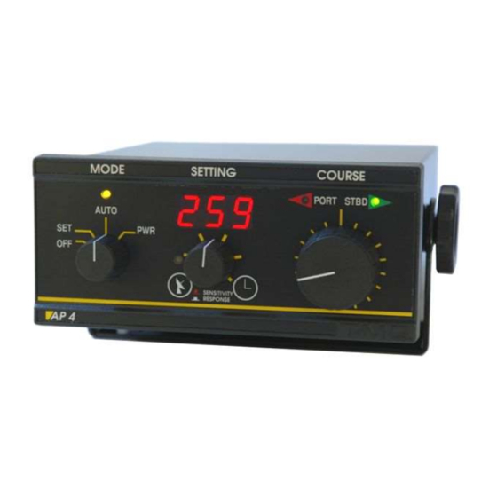
Introduction The AP4 autopilot is a rugged & reliable pilot for use on all sorts of vessels, motor or sail, commercial or pleasure. These pilots have been in production for many years and are widely used by professional fishermen because of their dependability. The front panel features large control knobs for ease of use in all sea conditions. - Page 7 See the Operation section of this manual for details. For more information on installation of your AP4 autopilot, see the Autopilot Installation section of this manual. For more information on using your AP4 autopilot, see the Autopilot Operation section of this manual.
-
Page 8: Autopilot Operation
Autopilot Operation Overview: The following is a brief list of the capabilities of the AP4 autopilot. Each is described in more detail in a separate chapter. Set/Standby Mode The digital display shows the current magnetic heading. The autopilot will not apply any steering control. -
Page 9: Set (Standby) Mode
Rudder Response, Sensitivity These controls customise the AP4 for your vessel. They may also be used to adjust steering for varying sea conditions. Commercial Watch Timer For vessels under survey requirements. The timer can be set to give a warning alarm at a preset time and output for a loud external alarm after 6 minutes. -
Page 10: Auto Mode
(mode LED indicator would be off). To re-engage the autopilot, use the remote unit switch or move the mode switch to SET then back to AUTO. TMQ AP4 Autopilot Page 10 of 63 Ver1.0... -
Page 11: Power Steering Mode
The maximum angle of rudder is controlled by Rudder Limit setting (see installation section). For information on Power Steering with a remote unit (eg steering levers), see the section on remote units. TMQ AP4 Autopilot Page 11 of 63 Ver1.0 22/05/2007... -
Page 12: Gps Mode
GPS unit, at a maximum rate of 10 degrees per second. If no GPS data is being received by the AP4, the autopilot will lock onto the course of the vessel at the time that GPS Mode was engaged, and the No GPS Data alarm will sound. - Page 13 The GPS unit must be set up to output "NMEA 0183" data on a pair of wires which are connected to pins 1 (RX +) and 2 (RX -) of the AP4 NMEA IN/OUT socket. A suitable cable to match your GPS can be prepared by the installer of your autopilot or the dealer from whom you purchased your autopilot.
- Page 14 GPS unit is set to "auto-sequence" between them and an "arrival zone" of more than 0.1 NM (nautical miles) is set so that the GPS can detect when the vessel has reached a waypoint, then the AP4 will be able to steer from each waypoint to the next without intervention.
- Page 15 The bearings generated by the GPS unit must correspond to the bearings the AP4 is receiving from its magnetic compass. The greater the difference between these bearings, the less accurate will be the GPS Mode steering. Ensure that the GPS unit has the correct magnetic correction.
-
Page 16: Watch Timer Mode
The commercial watch timer feature is built in to the AP4 but is normally disabled and functions as for pleasure boat (see above). The external alarm unit is not supplied with the AP4 but is available as an option. -
Page 17: To Enable The Commercial Watch Alarm
6. Press TIMER button, display then reverts to normal heading. NOTE: Once the commercial watch alarm has been enabled, it cannot be disabled by the user. To connect an external alarm to the AP4 refer to Install Alarm Siren on page 46. TMQ AP4 Autopilot Page 17 of 63 Ver1.0... -
Page 18: Remote Auto Steer (Remote Unit Operation)
Engaging Auto Steer Mode The AP4 mode must be Set, Auto or PWR for the remote to operate. Change the switch on the remote unit to the AUTO STEER position. If the switch is already in the AUTO STEER position, move switch to OFF and then back to AUTO STEER. -
Page 19: Remote Power Steer (Remote Unit Operation)
Engaging Remote Power Steer Mode The AP4 mode must be Set, Auto or PWR for the remote to operate, centre the remote unit course knob and switch the remote unit to the POWER STEER position. If the switch is already at the POWER STEER position, move switch to OFF and then back to POWER STEER. - Page 20 A function in the AP4 S8 version allows for a steering wheel input on pin 5 of the remote socket. Selection of this mode in the software allows for full electric steering on the vessel. (See section ‘AP4 Special modes’).
-
Page 21: Rudder Response (Rudder Ratio) Control
When the rudder response setting is too low, turns will take an excessive amount of time, and the vessel may "wander". When the rudder response setting is too high, turns will be rapid and the vessel will oversteer. TMQ AP4 Autopilot Page 21 of 63 Ver1.0 22/05/2007... - Page 22 Experiment to find the best settings for your particular vessel. Only make small changes at a time. The control unit remembers the response setting when the unit is turned off. TMQ AP4 Autopilot Page 22 of 63 Ver1.0 22/05/2007 (AP4S8)
-
Page 23: Sensitivity
Note: If the centre knob is not pushed in the rudder position will be displayed. TMQ AP4 Autopilot Page 23 of 63 Ver1.0 22/05/2007... -
Page 24: Angle Off Course Alarm
The alarm may also sound when changing from one section of a GPS route to another, and will cancel itself when the course change is completed. See also the Alarms section of this manual. TMQ AP4 Autopilot Page 24 of 63 Ver1.0 22/05/2007... -
Page 25: Alarms
45 degrees from course-to-steer. No GPS Data Alarm The alarm sounds 0.5 seconds on, 0.5 seconds off if the autopilot is not receiving valid information from the GPS. Rudder Indicator Display TMQ AP4 Autopilot Page 25 of 63 Ver1.0 22/05/2007 (AP4S8) -
Page 26: Counter Rudder Settings
The AP4 S8 can display Rudder Position as a number of degrees port or starboard. When pulling the centre knob out the initial display will be sensitivity setting and then will display rudder position. Counter Rudder Settings The Mode 913 allows the counter rudder settings to be turned on or off and the decay time to be set. -
Page 27: Autopilot Installation
In the case of SSB radios, the distance should be increased to 2 metres (7 feet). Genuine TMQ cables should be used at all times. Cutting and rejoining these cables could compromise EMC performance and should be avoided unless doing so is suggested in the installation instructions. -
Page 28: Checking
Interconnection:- If your TMQ equipment is going to be connected to other equipment using a cable not supplied by TMQ, a suppression ferrite MUST always be fitted to the cable close to the TMQ unit. -
Page 29: List Of Components
List of Components BEFORE INSTALLATION, ENSURE YOU HAVE PURCHASED THE CORRECT PARTS FOR YOUR VESSEL. TMQ Electronics Autopilots are intended for use in three (3) basic systems: The control unit can be used to drive most brands of Slave Units or Oil Control Valves (power steering). -
Page 30: Installation Of Main Unit
Installation of Main Unit Position The AP4 should be mounted in an accessible position, protected from rain or salt water. If autopilot control is required from an exposed steering position, fit an additional remote steering panel. Wiring Access for wiring must be provided. Cabling will have to be run to the rudder feedback unit, compass unit and steering drive system. -
Page 31: Installation Of Compass
Before fixing the sensor in place, align it carefully so that the AP4 compass displays the same bearing as the ships compass. A compass top sensor is recommended for steel vessels provided a suitably compensated steel boat compass is fitted to the vessel. -
Page 32: Installing An Elproma Nmea Compass
I.e. Speakers. . The compass must be mounted in a near vertical position. The cable runs through the cutout at the back of the AP4. Power for the compass is from the Terminals marked A+ and is regulated at 10 volts. - Page 33 After initial sea trials, you may wish to recalibrate the compass, although in most cases the factory calibration will be as good as or better than calibration achieved on the vessel. See the Compass Calibration Section. TMQ AP4 Autopilot Page 33 of 63 Ver1.0 22/05/2007...
- Page 34 If the magnetic sensor unit and compass top sensor are interchanged, the compass detector DIP switches must be altered. The Top cover of the AP4 has to be removed. The DIP switch is identified as component DIP1 on the PCB component overlay diagram at the rear of this manual.
-
Page 35: Installation Of Rudder Feedback
Wiring The magnetic sensor unit or compass-top-sensor, which comes with your AP4 autopilot is fitted with a plug, which fits into the socket, labelled "compass" on the rear of the autopilot. If the cable must be extended, we recommend that a good quality 5-core shielded extension cable be used. - Page 36 This must be specified when ordering the autopilot control unit. If a RFUS is used DIP 2 should be set to OFF. If a RFUH is used DIP 2 should be set to ON. TMQ AP4 Autopilot Page 36 of 63 Ver1.0 22/05/2007...
-
Page 37: Heavy Duty Rudder Feedback Installation Diagram
Heavy Duty Rudder Feedback Installation Diagram TMQ AP4 Autopilot Page 37 of 63 Ver1.0 22/05/2007 (AP4S8) -
Page 38: Standard Rudder Feedback Installation Diagram
Standard Rudder Feedback Installation Diagram TMQ AP4 Autopilot Page 38 of 63 Ver1.0 22/05/2007 (AP4S8) - Page 39 ALIGNED. THE ARM SHOULD NOT BE REMOVED OR LOOSENED UNNECESSARILY. IF ARM IS LOOSENED OR REMOVED, VOLTAGE ALIGNMENT SHOULD BE CHECKED BEFORE USING THE AUTOPILOT. THIS MUST BE DONE BY A COMPETENT TECHNICIAN. TMQ AP4 Autopilot Page 39 of 63 Ver1.0 22/05/2007 (AP4S8)
-
Page 40: Installation Of Remote Units
The cable leading from the unit should be connected to the remote socket of the AP4, as shown in the connection diagram. Panel Remote This unit is very robust and may be mounted where it is subject to occasional splashes of water. -
Page 41: Hydraulic Drive Installation
Hydraulic Drive Installation The AP4 autopilot can drive spool valves, relays or hydraulic pumps. TMQ can supply the following pump units: 1. A constant running pump set (including spool valves) for 24V DC operation with flow rate up to 4000cc per minute. - Page 42 Solenoid Valves Links are provided to allow jog lever operation in conjunction with AP4 S8 Autopilot. When cut (open circuit) the Autopilot only pulls the outputs low. Positive being supplied to the Solenoid common. Links are marked J1 and J2 on the PCB.
-
Page 43: Drive Connection Diagrams
Drive Connection Diagrams TMQ AP4 Autopilot Page 43 of 63 Ver1.0 22/05/2007 (AP4S8) -
Page 44: Nmea Connection
NMEA Connection Data In For GPS navigation, connect the GPS unit data output and data return wires to the NMEA socket at the rear of the AP4. Data In Connection - Examples only: Refer to connection diagram. For any GPS or Plotter with open wires follow the relevant operation manual of the unit. - Page 45 2 = HDM Only 3 = HDT Only 4 = HDG Only 5 or 6 there is no output. 3. Press the Timer button to save the setting and exit the set-up procedure. TMQ AP4 Autopilot Page 45 of 63 Ver1.0 22/05/2007 (AP4S8)
-
Page 46: Heading Data Input
Receive data Positive Blue Link from Neg to RXD- (Brown to Black) If the NMEA data is not present the AP4 will display the heading received from the standard compass. If the NMEA data fails during operation the unit will revert to the standard compass and the alarm will sound. - Page 47 Install External Alarm Siren 1. Uncover AP4 top by unscrewing the 2 X M3 Pan Head screws on either side 2. Identify T6 AUX Terminal on AP4 board 3.
-
Page 48: Commissioning Checks
AUTO light will come on. CAUTION: IF AUTOPILOT DRIVES HARD OVER, IMMEDIATELY TURN CONTROL UNIT OFF. Reverse motor drive wires at terminal strip on rear of autopilot and repeat from Step 1. TMQ AP4 Autopilot Page 48 of 63 Ver1.0 22/05/2007 (AP4S8) - Page 49 The autopilot is now ready for full operational testing. Use open waterways for testing until you are familiar with the operation. Complete installation and commissioning form supplied and Return to TMQ TMQ AP4 Autopilot Page 49 of 63 Ver1.0 22/05/2007...
-
Page 50: Rudder Limits Switch Setting
Hold down GPS button, press TIMER button, display shows [900]. Dial up [905] by COURSE knob, press TIMER button. Display shows rudder position as a scale of 0 to 255, 128 being the centre. TMQ AP4 Autopilot Page 50 of 63 Ver1.0 22/05/2007 (AP4S8) -
Page 51: Compass Calibration
If the AP4 compass displays a constant offset (eg the autopilot compass reads 3 degrees high on all bearings), simply rotate the AP4 compass case to align bearings with the ships compass. It is not necessary to re-calibrate the compass as described below. -
Page 52: Calibration Elproma Compass
Release buttons, rotate course knob until display shows [902]. Press TIMER button. Note: If display shows [rES] the calibration was invalid and the AP4 defaults the factory setting. Repeat steps 1, 2 and 3 to carry out calibration again. - Page 53 AP4 Special Modes Display Selection Button Operation 901 Start compass calibration [CAL]: TIMER 902 Store compass calibration: TIMER 903 Return to default calibration [rES]: TIMER 904 Factory test for calibration ----- 905 Set limit switches: TIMER/GPS (Port) TIMER/GPS (Stbd) Set limit to maximum:...
-
Page 54: Optional Extras
Optional Extras There are a range of optional extras that can be connected to the TMQ AP4 system as the need or circumstances require. The AP4 system can be adapted to suit many applications. Further information can be obtained from the TMQ website at www.tmq.com.au... -
Page 55: Remotes
Remotes Panel Remote The TMQ panel remote provides basic autopilot control providing course changes from a second station such as a flybridge. Hand Remote Active Remote Hand remotes and Active remotes provide the freedom to maintain full control of the autopilot and steering while moving around the vessel. -
Page 56: Hydraulic Drives And Pump Units
Continuous pumps Constant running pumps available in 2 or 3 litre for 12 volt DC systems. Accurate flow adjustment to set lock-to-lock time. TMQ AP4 Autopilot Page 56 of 63 Ver1.0 22/05/2007 (AP4S8) - Page 57 Mechanical drive units in 12 or 24 volt DC to suit vessels with existing mechanical steering. Supplied with standard chain and socket. Computer Software TMQ AP1000 Autopilot operating Software. Computer control program enabling autopilot control from a standard PC with serial COM ports. (Cable required)
-
Page 58: Wiring Colours
Motor A Normally High, Switched to negative to drive NMEA In / Out GPS In GPS Return Data Out to TMQ Display or PC Negative Data in from TMQ display or PC + 10 V out Remote + 5 Volts... -
Page 59: Circuit
Circuit TMQ AP4 Autopilot Page 59 of 63 Ver1.0 22/05/2007 (AP4S8) - Page 60 PCB Layout TMQ AP4 Autopilot Page 60 of 63 Ver1.0 22/05/2007 (AP4S8)
- Page 61 TEL: +61 7 3890 7788 FAX: +61 7 3890 7799 Declares under our sole responsibility that the products: AP4 Autopilot, Compass Sensor, Rudder Feedback unit and remote accessories, all units interconnected with necessary cables and external connections as a system...
-
Page 62: Warranty
All units in need of repair will be repaired without charge to the purchaser during the above mentioned period in accordance with the following terms and conditions: The defective unit is returned "freight prepaid" to TMQ Electronics 1/18 Alexandra Place, Murarrie, QLD. 4172. Proof of purchase is supplied and original Serial Numbers on equipment have not been changed. -
Page 63: (Ap4S8)
TMQ Electronics shall not be liable for damage or loss incurred resulting from the use and operation of this product. TMQ Electronics reserves the right to make changes or improvements to later models without incurring the obligation to install similar changes to equipment already supplied.
Need help?
Do you have a question about the AP4 and is the answer not in the manual?
Questions and answers