
Related Manuals for TMQ AP56


Summary of Contents for TMQ AP56
- Page 1 AP56 AU TO P I LOT Installation and Service Manual Unit 18, 17 Rivergate Place Murarrie QLD 4172 T: +61 07 3640 5600 E: tmq@tmq.com.au www.tmq.com.au IMPORTANT: PLEASE RETAIN ON BOARD...
- Page 2 (This page intentionally left blank)
-
Page 3: Table Of Contents
Power Steer Mode GPS Mode – Waypoint Steering Backlighting Rudder Angle Indicator Remote Operation Alarms Off Course No GPS Data No MCU No Heading Data Installation Main Display Unit Second Station Display Unit AP56 Display Connections Declaration of Conformity Warranty Additional Information... -
Page 4: Introduction
This manual should only be read in conjunction with the associated electric amplifier (C-Drive MCU) or autopilot control unit (AP4/AP9). The AP56 Display is the main control panel used in conjunction with a C-Drive Steering amplifier to form an AP56 Autopilot System. It provides the means to fully control the autopilot system, indicating in different modes heading, course to steer and rudder angle. -
Page 5: System Configuration
System configuration Options: • Compass Top Sensor An AP56 Autopilot system comprises • Heavy Duty Rudder Sensor the following minimum units: • Second Station Display Unit Essential Electronics: • Remote Station Devices including: • AP56 Display. 1. Active remote • C-Drive motor control unit 2. - Page 6 System Overview Rudder actuator systems may comprise any of the following: The AP56 Display head utilises the C-Drive assembly and provides full 1. Hydraulic ram controlled by either: control of the autopilot, indicating in • Solenoid valves fitted to an existing different modes heading, course to power steering system.
-
Page 7: Definition Of Terms
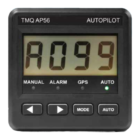
Definition of Terms Heading: AP56 Display: The magnetic heading of the vessel The Operation unit, with LCD Display at the current time. and pushbuttons. Course-to-steer: C-Drive Assembly: The magnetic heading which the The Electric Steering control autopilot is attempting to achieve. -
Page 8: Overview Of Operation
C-Drive amplifier. It is RUDDER ANGLE DISPLAY: the C-Drive, which generates signals to the steering motor. The AP56 Display Unit LCD can be set to display the rudder angle as a The following is a brief list of the numeric number. -
Page 9: Initial Settings
• Display will read PL - - (- - is the need to be carried out prior to port rudder angle º ) using the AP56 Autopilot. Two initial settings can be carried out using • Press ◄ and ► buttons together the display controls;... -
Page 10: Rudder Limit Reset
• Display will read StrC The standard TMQ compass (COMMAG or E-Compass) supplied • Commence turning the boat slowly as part of the AP56 autopilot system in one direction for two full circles has been calibrated after manufacture (720º). Each circle should take a and this calibration will be satisfactory minimum of 1 minute. -
Page 11: Heading Sensitivity
To adjust sensitivity: It is important to realise that on any vessel the ship’s compass can have • Press MODE button heading errors as a result of the • Display will read S * * - present vessel’s magnetic signature. These setting (**) will be between errors can be minimised by having the ship’s compass swung and... -
Page 12: Operation Of Autopilot
• AUTO LED will light The rudder angle may be controlled • Autopilot locks on to current by the buttons ◄ and ► on the AP56 heading panel or from one of the remote • Display reads “A***” – course to steering stations. -
Page 13: Gps Mode - Waypoint Steering
For engaging this mode, when in The AP56 will be able to steer from MANUAL mode press the buttons each waypoint to the next without AUTO and MODE at the same time. intervention under the following Once in power steer mode, press ◄... -
Page 14: Backlighting
To exit rudder angle display: If no GPS data is received by the • Press MODE or AUTO button AP56, the autopilot will lock onto the Remote Operation course of the vessel at the time that GPS Mode was engaged, and the The AP56 autopilot can use the “NO GPS DATA”... - Page 15 Display indication for remote auto To revert to main display control: control: • Press AUTO on main control • AUTO selected by remote control • AUTO LED will be lit on main • AUTO and REM LED’s on main control display will be lit •...
-
Page 16: Alarms
• Ensure the GPS unit has the activate when the boat is more than correct magnetic correction factor 45º off the required course. • Ensure that the AP56 compass is • Audible alarm will sound correctly installed, aligned, and not • AUTO LED will flash subject to magnetic interference. -
Page 17: No Heading Data
C-Drive, or via AP56. For receiving NMEA data via AP56, the external device has to be attached to the AP56, and the AP56 will forward the incoming data automatically to its other port, which is connected to C- Drive. -
Page 18: Installation
• Connect cable to NMEA socket on NOTE: Both connector sockets of C-drive the AP56 have the same functions, i.e., the power supply and the • For feeding C-Drive with NMEA communication pins. data via AP56 head, connect an... - Page 19 Pin 1 ....+10 V.............. Pin 6 Pin 2 ....Negative ............Pin 4 Blue Pin 3 ....Not connected Pin 4 ....TMQ Data Tx + ..........Pin 5 Yellow Pin 5 ....TMQ Data Rx + ..........Pin 3 Green Pin 6 ....
-
Page 20: Declaration Of Conformity
Standard(s): EN60945/1997 CEI IEC945/1996 For TMQ International Pty. Ltd. Murarrie Queensland Australia. August 2020 Dale Sinclair, Manager 18 of 22 TMQ AP56 - SS37... -
Page 21: Warranty
Warranty TMQ products are thoroughly TMQ shall not be liable for damage inspected and tested before shipment or loss incurred resulting from the use from the factory and are warranted and operation of this product. to be free of defects in workmanship... - Page 22 Notes 20 of 22 TMQ AP56 - SS37...
- Page 23 (This page intentionally left blank)
- Page 24 Unit 18, 17 Rivergate Place Murarrie QLD 4172 T: +61 07 3640 5600 E: tmq@tmq.com.au www.tmq.com.au...
Need help?
Do you have a question about the AP56 and is the answer not in the manual?
Questions and answers