Advertisement
Quick Links
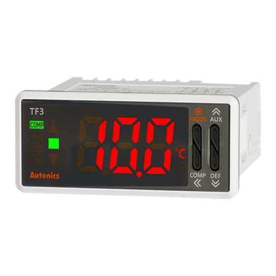
TF3 Series
TF3 Series
Refrigeration Temperature Controller
Features
● ● ● S tandard installation size for refrigeration and air-cooling panels
(W70.3×H28.2mm)
● Various compressor load current capacity: 5A, 16A, 20A
● Various user-friendly functions:
- Defrost sync function:
simultaneous defrost operation of multiple controllers (up to 6 units)
- RTC (Real Time Clock) function:
night mode operation and real-time defrost control
- Built-in alarm function
● Remote monitoring of real-time temperature and output control
(using TFD series remote display unit, sold separately)
● Communication output models available: RS485 (Modbus RTU)
● Parameter configuration via PC (RS485 communication)
- DAQMaster software included (comprehensive device management software)
● IP65 protection structure (IEC standard): front panel only
Please read "Safety Considerations" in operation
manual before using.
Manual
● Visit our website (www.autonics.com) to download user manual and communication manual.
● User manual describes for specifications and function, and communication manual describes for RS485 communication
(Modbus RTU protocol) and parameter address map data.
Comprehensive Device Management Program (DAQMaster)
● DAQMaster is comprehensive device management program. It is available for parameter setting, monitoring, and user
parameter group setting, parameter mask setting for only TF3 Series.
● Visit our website (www.autonics.com) to download user manual and comprehensive device management program.
< Computer specification for using software >
Item
Minimum requirements
IBM PC compatible computer with Intel Pentium Ⅲ or above
System
Operating system Microsoft Windows 98/NT/XP/Vista/7/8/10
Memory
256MB or more
Hard disk
More than 1GB of free hard disk space
VGA
1024×768 or higher resolution display
Others
RS-232 serial port (9-pin), USB port
H-2
< DAQMaster screen >
NEW
Advertisement

Related Manuals for Autonics TF31-A


Summary of Contents for Autonics TF31-A
- Page 1 ● DAQMaster is comprehensive device management program. It is available for parameter setting, monitoring, and user parameter group setting, parameter mask setting for only TF3 Series. ● Visit our website (www.autonics.com) to download user manual and comprehensive device management program. < Computer specification for using software >...
-
Page 2: Ordering Information
1 sec. Check the connection with TF3. Software ※ When connecting TFD to the data loader port of TF3, you cannot connect Autonics SCM-US (USB to Serial converter, sold separately). for communication. Use SCM-US48I(USB to RS485 converter, sold separately), SCM-38I(RS232C to... -
Page 3: Specifications
TF3 Series Specifications TF3 Series Model TF31- TF33- Number of channels AC power 100-240VACᜠ 50/60Hz Power sup- AC/DC power 24VACᜠ 50/60Hz, 12-24VDCᜡ Allowable voltage range 90 to 110% of rated voltage AC power Max. 8VA (100-240VACᜠ 50/60Hz) Power consumption AC/DC power Max. - Page 4 Refrigeration Temperature Controller Connections Photoelectric Sensors ※ Use crimp terminals of size specified below. Fiber Optic Sensors <Crimp terminal> Door/Area Terminal number Sensors General 1 to 4 4 to 6mm Max. 1.7mm Max. 3.7mm TF3 - 5 to 10 6 to 8mm Max.
- Page 5 TF3 Series Dimensions (unit: mm) TF3 Series 74.3 NTC sensor (5kΩ) Bracket AWG22 TPE lead wire Soldering 5±1 Max. 15 23.9 2000±50 Panel cut-out (unit: mm) Size Series ※ 1 Min. 100 Min. 55 70.3 28.2 + 0.7 + 0.5 Min.
- Page 6 It is for displaying TF3 data at remote display unit (TFD) by connecting phone-jack. In other case, for connecting Autonics SCM-US (USB/Serial converter, sold separately), it is a PC loader port of serial communication for parameter setting or monitoring by PC.
- Page 7 Press any key among the keys to return to password entering window. Press the (MODE) key to return to RUN mode. If you forget password, contact Autonics after checking password code. ※ 2. It appears when setting user parameter group in the comprehensive device management program (DAQMaster).
- Page 8 Refrigeration Temperature Controller Photoelectric Sensors 3sec Fiber Optic Sensors Door/Area Sensors Proximity Parameter 2 group Parameter 3 group Parameter 4 group Parameter 5 group Sensors [ PA2 ] [ PA3 ] [ PA4 ] [ PA5 ] Pressure Sensors Comp. output mode [ OFT ] Defrost method &...
- Page 9 TF3 Series Parameter 1 Group ※1. : Press any key among keys. ※ After entering setting mode, hold the (MODE) key anytime for 3 sec to return to RUN mode. 3 sec RUN mode ※ After entering setting mode, hold the (MODE) key anytime for 1.5 sec to go to the concerned group name.
- Page 10 Refrigeration Temperature Controller Parameter 2 Group ※1. : Press any key among keys. ※ After entering setting mode, hold the (MODE) key anytime for 3 sec to return to RUN mode. Photoelectric 3 sec RUN mode ※ After entering setting mode, hold the Sensors (MODE) key anytime for 1.5 sec to go to the concerned group name.
- Page 11 TF3 Series Night mode end hour ※ Appears for RTC function Setting range: 0 to 23 hour model. ※ Does not appear when night mode [ nMD ] is set as Night mode [ OFF , DI ]. end min. Setting range: 0 to 59 min Temperature monitoring...
- Page 12 Refrigeration Temperature Controller Parameter 3 Group ※1. : Press any key among keys. ※After entering setting mode, hold the (MODE) key anytime for 3 sec to return to RUN mode. Photoelectric ※ After entering setting mode, hold the Sensors (MODE) key anytime for 1.5 sec to go to the concerned 3 sec RUN mode group name.
- Page 13 TF3 Series Defrost when power ON Defrost delay when power ON/manual defrost Setting range: 0 to 60 min Defrost group Parameter copy Prior defrost selection Defrost time unit Alarm delay after defrost/door open Setting range: 0 to 24 hour Temperature display during defrosting Parameter 4 Group ※1.
- Page 14 Refrigeration Temperature Controller Photoelectric Sensors Alarm high-limit deviation Fiber Optic Sensors Setting range: -F.S. to F.S Alarm low-limit deviation Door/Area Sensors Proximity Alarm hysteresis Sensors Setting range: 1 to 5℃ (0.5 to 5.0℃), 2 to 10℉ (2.0 to 10.0℉) Pressure Sensors Alarm ON delay time Rotary...
- Page 15 TF3 Series ※1. : Press any key among keys. Parameter 5 Group ※After entering setting mode, hold the (MODE) key anytime for 3 sec to return to RUN mode. ※ After entering setting mode, hold the (MODE) key anytime for 1.5 sec to go to the concerned 3 sec RUN mode group name.
-
Page 16: Parameter Reset
Refrigeration Temperature Controller Photoelectric Sensors User level Fiber Optic Sensors SV setting group lock Door/Area Sensors Proximity Sensors Front key lock Pressure Sensors Parameter group lock Rotary Encoders Connectors/ Connector Cables/ Sensor Distribution Password Boxes/ Sockets Temperature Controllers SSRs / Power Controllers Counters Parameter Reset... - Page 17 TF3 Series Front Panel Display When Power Is On When power supplies to the unit, whole display part flashes approx. 1 sec. The display part displays model specification (no. of input CHs, output, power supply, compressor load capacity, option function), flashes input type twice and the unit returns to RUN mode to operate.
- Page 18 Refrigeration Temperature Controller Factory Default Photoelectric Sensors Parameter 0 group SV setting [ Parameter Factory default Parameter Factory default Fiber Optic Sensors Door/Area Parameter 1 group [ Sensors PAR1 Parameter Factory default Parameter Factory default Parameter Factory default Proximity Sensors Pressure Sensors Rotary...
- Page 19 TF3 Series Alarm (Except 1CH, Compressor Output Model: TF31-1 Set both alarm operation and alarm option by combining. Alarm function is available for compressor+defrost or auxiliary (alarm/evaporator-fan) output model (TF3 -2 - ). Also defrost/auxiliary output [ sDA ] of parameter 1 group should be set as auxiliary [ AUX ], and auxiliary output [ AUX ] should be set as alarm [ ALM ].
- Page 20 Refrigeration Temperature Controller Functions Photoelectric Compressor protection Sensors This function is for preventing compressor from life cycle shortening or malfunction by overload and frequent ON/OFF Fiber of compressor. As compressor protection settings, when compressor output does not ON, the front compressor (COMP) Optic Sensors output indicator (green) is flashing.
- Page 21 TF3 Series Defrost control (except 1CH, compressor output model: TF31-1 When operating a compressor for a long time, an evaporator and a freezer are freezing and thermal efficiency of compressor is decreased. For increasing thermal efficiency, defrost operation helps to remove frost or ice around of evaporator.
- Page 22 Refrigeration Temperature Controller Evaporator-fan control (except 1CH, compressor output model: TF31-1 Photoelectric To improve the efficiency of cooling, install and control evaporator-fan at evaporator. Sensors It is available for compressor+defrost or auxiliary (alarm/evaporator-fan) output model (TF3 -2 - ). Also defrost/ auxiliary output [ sDA ] of parameter 1 group should be set as auxiliary [ AUX ], and auxiliary output [ AUX ] should be set Fiber Optic...
- Page 23 Masked parameters are only not displayed. The setting value of masked parameters are applied. For more information, refer to DAQMaster user manual. Visit our web site (www.autonics.com) to download DAQmaster program and the user manual. Before applying mask After applying mask...
-
Page 24: Error Display
User parameter group can have up to 30 parameters in the comprehensive device management program (DAQMaster). Fiber Optic For more information, refer to the DAQMaster user manual. Sensors Visit our web site (www.autonics.com) to download the DAQMaster program and the user manual. Door/Area RUN mode Sensors Proximity Sensors... - Page 25 TF3 Series Proper Usage Cautions during use ● Follow instructions in 'Cautions during use'. Otherwise, It may cause unexpected accidents. ● Check the polarity of the terminals before wiring the temperature sensor. For RTD temperature sensor, wire it as 3-wire type, using cables in same thickness and length. For thermocouple (CT) temperature sensor, use the designated compensation wire for extending wire.
Need help?
Do you have a question about the TF31-A and is the answer not in the manual?
Questions and answers