
Related Manuals for Nedap VP1006


Summary of Contents for Nedap VP1006
- Page 1 Service manual For installation, operation and service OEM ISO Reader VP1006 06 - 2017 / Manual version 2.6...
- Page 2 © Nedap N.V., Livestock Management P.O. Box 104 NL-7140 AC GROENLO The Netherlands VP1006-200PM-00 OEM ISO Reader...
-
Page 3: Table Of Contents
Appendix E: RS485 connections with separated wiring Appendix F: RS485 connections with Nedap Velos cable Appendix G: RS232 connections Appendix H: VP1006 connected to a Velos VP8001 (VPU) Appendix I: Neutrodynisation unit between two antennas VP1006-200PM-00 OEM ISO Reader Manual version 2.6... - Page 4 VP1006-200PM-00 OEM ISO Reader Manual version 2.6...
-
Page 5: Introduction
EWA transformer with stainless steel antenna strip HDPE antenna with HDPE antenna tuner The VP1006 must be installed in a housing suitable for farm conditions, for example in a V-box. Figure : V-box2 with a VP2002 power supply and a VP1006 reader... - Page 6 VP6041 and VP6042 regarding hardware are the same. The VP6041 is adjusted for environments with lots of steel for short distances (pigs). The VP6042 is adjusted for longer distances (1 m) recognition (Cows). VP1006-200PM-00 OEM ISO Reader Manual version 2.6 / Page...
-
Page 7: Description And Functioning
There are also 6 outputs available to activate e.g. lights, motors, valves or relays. The VP1006 can read tags FDX/HDX 134.2 kHz. The VP1006 must be connected to a computer and can communicate by a CAN, RS485 or RS232 protocol. The connected computer must give controlling commands to the VP1006 to operate inputs, outputs and identification. -
Page 8: Connections
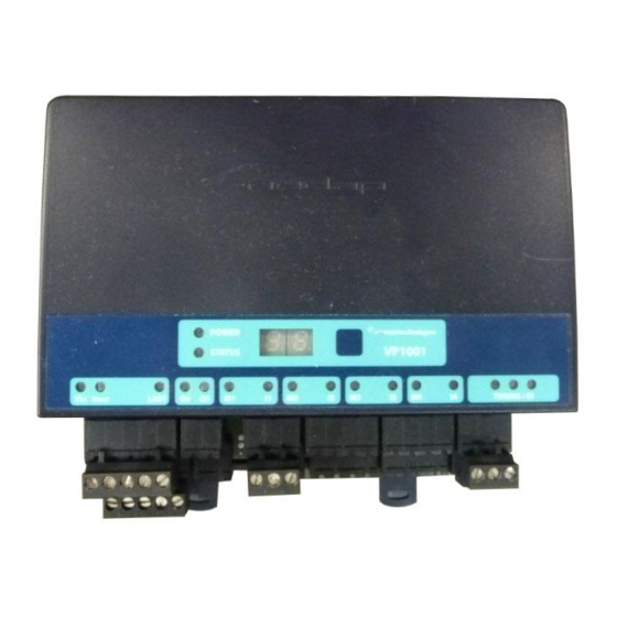
E, F and G for the different connection possibilities. Light Switch Velos cable Feed motor Figure : I/O of the VP1006. The feed motor, input and output connections are shown above as an example. Details VP1006 inputs and outputs Power Minus... -
Page 9: Adjustments
5.1 Check after power up Check if the VP1006 has power after power up. This means 3 green LED’s are on, see figure below. For more details about the LED indicators see Appendix D. If LED’s are green, continue with address settings 5.2 Communication bus termination jumper... -
Page 10: Address
5.3 Address Each VP1006 requires a unique address on the communication bus. Use the display and push button to set the address. How to use the display and push button is shown in appendix B. See appendix C for the complete overview of the display menu. -
Page 11: Antenna Tuning With Ewa Antenna Transformer
When it is not possible to get a green LED use another connection and try again. 5.6 Software setup The software in the connected controller determines how the inputs and outputs on the VP1006 are controlled. See manual with the relevant settings to configure the software for this VP1006. -
Page 12: Advanced
There are two types of output tests. An output test to switch the output on and off, and an output test especially for Nedap feed motors. There is also available an input test for checking connected equipment like switches and sensors. -
Page 13: Advanced Antenna Adjustment
6. If reading distance is ok leave the menu. If not ok try another level. 7. To leave the service menu and return to normal operation, press the button until the display goes blank (press about 4 seconds) VP1006-200PM-00 OEM ISO Reader Manual version 2.6 / Page... -
Page 14: Identification Test Options
Signal level indication option “SF” and “SH” There is a test available to give an indication about the signal received on the reader of the VP1006. This test is separated in a FDX (SF) and HDX (SH) noise indication test. This test is mainly used for HDX because at HDX there is a greater risk of external influence on the antenna field. -
Page 15: Trouble Shooting
No regular maintenance required. Software update A VP1006 is equipped with software to activate inputs and outputs, display / push button and a motor safeguard. This software is called firmware. During manufacturing the firmware is programmed and ready for use. In case of an update it is possible to download new firmware thru the CAN-bus. In the Velos system the web browser interface of the VPU (VP8001) is used to handle this. -
Page 16: Appendix A: Specifications / Ce
IP 30. When installed in V-box IP 65 (cover and cables installed correctly !) Always use a NEDAP power supply. The Nedap guarantee-regulations are only valid when is installed as indicated in this manual. Install data cables at a safe distance from (high) powered cables For more detailed information contact your local Nedap supplier or check the internet site. - Page 17 VP1006-200PM-00 OEM ISO Reader Manual version 2.6 / Page...
-
Page 18: Appendix B: Display And Push Button
Check a setting select the item to check, press button until blinking, first value shown is actual setting The display is normally automatically switched off after 30 minutes. VP1006-200PM-00 OEM ISO Reader Manual version 2.6 / Page... -
Page 19: Appendix C: Overview Display Menu
COMMUNICATION PROTOCOL Enter a number to set the right settings (see table next page) Press button until blinking To leave menu: Short press on button Press button until display goes blank VP1006-200PM-00 OEM ISO Reader Manual version 2.6 / Page... - Page 20 RS232 with Texas Instruments protocol* RS232 Texas Instruments protocol *Serie 2000 reader systems ASCII protocol, 9600 baud, 8 databits, no parity, 1 stopbit Default factory settings: RS232, nedap extended protocol 9600 baud (CC=20 and CP=22) VP1006-200PM-00 OEM ISO Reader Manual version 2.6 / Page...
-
Page 21: Appendix D: Led Indicator Overview
TUNING /ID Green on Antenna ok Green blinking Antenna ok and tag identified Red on Antenna not tuned correctly Red on Antenna not tuned correctly Red blinking Antenna error / not connected VP1006-200PM-00 OEM ISO Reader Manual version 2.6 / Page... -
Page 22: Appendix E: Rs485 Connections With Separated Wiring
Appendix E: RS485 connections with separated wiring Shield not connected orange/white orange shield black Shield not connected orange/white orange/white orange orange shield shield black black orange/white orange shield shield To RS485 interface of computer black black VP1006-200PM-00 OEM ISO Reader Manual version 2.6 / Page... -
Page 23: Appendix F: Rs485 Connections With Nedap Velos Cable
Appendix F: RS485 connections with Nedap Velos cable orange/white orange shield blue/white blue black orange/white orange/white orange orange shield shield blue/white blue/white blue blue black black orange/white orange shield shield shield To RS485 blue/white interface blue/white blue of computer blue... -
Page 24: Appendix G: Rs232 Connections
Appendix G: RS232 connections Communication jumper Power supply RS232 cable specifications : Shielded cable Wires min. 0.34 mm Max length between PC and VP1006 15 meters RS 232 port of computer VP1006-200PM-00 OEM ISO Reader Manual version 2.6 / Page... -
Page 25: Appendix H: Vp1006 Connected To A Velos Vp8001 (Vpu)
Appendix H: VP1006 connected to a Velos VP8001 (VPU) orange/white orange/white orange orange shield shield blue/white blue/white blue blue black black orange/white orange/white orange orange shield shield blue/white blue/white blue blue black black orange/white orange/white orange orange shield shield blue/white... -
Page 26: Appendix I: Neutrodynisation Unit Between Two Antennas
3. Turn the wheels apart to the highest display value at reader B The display value and wheel distance apart can vary. Low display value means usually low coupling. Turn to max display value VP1006-200PM-00 OEM ISO Reader Manual version 2.6 / Page...
Need help?
Do you have a question about the VP1006 and is the answer not in the manual?
Questions and answers