Table of Contents
Advertisement
Quick Links
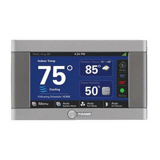
824 Comfort Control
Installation Guide
ALL phases of this installation must comply with NATIONAL, STATE AND LOCAL CODES
IMPORTANT — This Document is customer property and is to remain with this unit.
These instructions do not cover all variations in systems or provide for every possible contingency to be met in connection with
the installation. Should further information be desired or should particular problems arise which are not covered sufficiently
for the purchaser's purposes, the matter should be referred to your installing dealer or local distributor.
WORKS WITH
18-HD72D1-1
Advertisement
Table of Contents

Related Manuals for Trane 824 Comfort Control


Summary of Contents for Trane 824 Comfort Control
- Page 1 824 Comfort Control Installation Guide WORKS WITH ALL phases of this installation must comply with NATIONAL, STATE AND LOCAL CODES IMPORTANT — This Document is customer property and is to remain with this unit. These instructions do not cover all variations in systems or provide for every possible contingency to be met in connection with the installation.
-
Page 2: Table Of Contents
Installation Guide Contents 1. Safety ..............2 6. Basic Operation ........... 29 2. Product Specifications .......... 3 PI Control ............ 29 3. General Information ..........3 Load Value........... 29 Overview ............3 Duty Cycles ..........29 Features ............3 Overshoot Clamp ........29 Contents ............ -
Page 3: Product Specifications
824 Programmable Comfort Control Product Specifications SPECIFICATION DESCRIPTION Product Model TCONT824 Product XL 824 Comfort Control Size 5-1/2” x 3-3/8” x 1” (WxHxD) Storage/Operating Temperature -40°F to 175°F, 5% to 95% RH non-condensing Input Power 24VAC Power Consumption 7VA* Wire Usage... -
Page 4: Installation
Installation Guide Installation Network Connections To take advantage of the full range of features on the 824 Location Control, it should be connected to the Internet. This is The 824 Control is designed for installation in climate possible using either a wireless or a wired connection. controlled living spaces. -
Page 5: Wiring
This side mounts to wall 824 Programmable Comfort Control 7. Drill the holes in the wall where marked. FIGure 3. ATTACH RJ-45 HOLDER TO SUB-BASE If you are using a wireless Internet connection, skip to step 9. 8. If using a wired Ethernet connection, follow these step and refer to “Figure 3. - Page 6 Installation Guide Field Wiring Connection Diagrams Heat/Cool Diagrams PAGE DIAGRAM DESCRIPTION DIAGRAM 1 1 OR 2 STAGE COOLING W/TAM7 MODEL VARIABLE SPEED AIR HANDLER DIAGRAM 2 1 STAGE COOLING W/GAM5A OR TAM4 MODEL AIR HANDLER DIAGRAM 3 1 STAGE COOLING W/GAM5B MODEL VARIABLE SPEED AIR HANDLER DIAGRAM 4 2 STAGE COOLING W/GAM5B MODEL AIR HANDLER DIAGRAM 5...
-
Page 7: Heating And Cooling Applications
824 Programmable Comfort Control Heating and Cooling Applications 1- 1 or 2 Stage Cooling w/TAM7 Model Variable Speed Air Handler Diagram 1 - 1 or 2 Stage Cooling w/TAM7 Model Variable Speed Air Handler 824 COMFORT CONTROL AUX2 AUX 2 NOTES: AUX2 1. - Page 8 Installation Guide Diagram 3 - 1 Stage Cooling w/GAM5B Model Variable Speed Air Handler 3- 1 Stage Cooling w/GAM5B Model Air Handler 824 COMFORT CONTROL AUX2 AUX 2 NOTES: AUX2 1. “Y” terminal must be connected at indoor unit for high...
- Page 9 824 Programmable Comfort Control Diagram 5 - 1 Stage Cooling w/GAF2-S Model Air Handler 5- 1 Stage Cooling w/GAF2-S Model Air Handler 824 COMFORT CONTROL AUX2 AUX 2 AUX2 AUX1 AUX 1 INDOOR UNIT AUX1 24VAC HOT OUTDOOR UNIT COMMON...
- Page 10 Installation Guide 7- 1 Stage w/GAT2 & GAM2 Model Air Handler Diagram 7 - 1 Stage Cooling w/GAT2 & GAM2 Model Air Handler 824 COMFORT CONTROL AUX2 AUX 2 AUX2 AUX1 AUX 1 INDOOR UNIT AUX1 24VAC HOT OUTDOOR UNIT...
- Page 11 824 Programmable Comfort Control 9- 1 Stage Cooling w/Non-Variable Speed Gas Furnace Diagram 9 - 1 Stage Cooling w/Non-Variable Speed Gas Furnace 824 COMFORT CONTROL AUX2 AUX 2 AUX2 AUX1 AUX 1 INDOOR UNIT AUX1 24VAC HOT OUTDOOR UNIT COMMON...
- Page 12 3. Remove factory RC/RH jumper for systems with seperate heating and cooling low voltage transformers COMMON 4. ”BK” is not connected on non-Trane/American Standard units 5. “Y1/Ylo” and/or “Y/Y2” must be connected at the COOLING indoor unit on non-Trane/American Standard units...
- Page 13 AUX 2 NOTES: AUX2 1. Cut and remove the factory installted jumper at “BK” on the ECM fan control board AUX1 AUX 1 2. ”BK” is not connected on non-Trane/American PACKAGE UNIT AUX1 Standard units 24VAC HOT COMMON COOLING HEATING...
-
Page 14: Heat Pump Applications
Installation Guide Heat Pump Applications 15- 1 or 2 Stage Heat Pump w/TAM7 Model Air Handler Diagram 15 - 1 or 2 Stage Heat Pump w/TAM7 Model Air Handler 824 COMFORT CONTROL AUX2 AUX 2 AUX2 NOTES: AUX1 AUX 1 1. - Page 15 824 Programmable Comfort Control 17- 1 Stage Heat Pump w/GAM5B Model Air Handler Diagram 17 - 1 Stage Heat Pump w/GAM5B Model Air Handler 824 COMFORT CONTROL AUX2 AUX 2 AUX2 NOTES: AUX1 AUX 1 1. ”Y” terminal must be connected at indoor unit for...
- Page 16 Installation Guide 19- 1 Stage Heat Pump w/GAF2-S Model Air Handler Diagram 19 - 1 Stage Heat Pump w/GAF2-S Model Air Handler 824 COMFORT CONTROL AUX2 AUX 2 AUX2 AUX1 AUX 1 AUX1 INDOOR UNIT OUTDOOR UNIT 24VAC HOT COMMON...
- Page 17 824 Programmable Comfort Control 21- 1 Stage Heat Pump w/GAT2 & GAM2 Model Air Handler Diagram 21 - 1 Stage Heat Pump w/GAT2 & GAM2 Model Air Handler 824 COMFORT CONTROL AUX2 AUX 2 AUX2 AUX1 AUX 1 AUX1 INDOOR UNIT...
-
Page 18: Dual Fuel Applications
1. Cut and remove the factory installed “BK” jumper at INDOOR UNIT OUTDOOR UNIT the indoor unit AUX1 2. ”BK” is not connected on non-Trane/American 24VAC HOT Standard units 3. ”Y1” & “Y2” must be connected at the indoor unit on non-Trane/American Standard units COMMON 4. - Page 19 Thermostat) model THT1248 24VAC HOT (BAYSEN03ATEMPAA) is required for dual fuel, oil furnace applications 3. ”BK” is not connected on non-Trane/American COMMON Standard units 4. ”Y1” & “Y2” must be connected at the indoor unit on non-Trane/American Standard units COOLING 5.
-
Page 20: Power-Up Sequence
1. Cut and remove the factory installed “BK” jumper on them ECM fan control board OUTDOOR UNIT AUX1 2. ”BK” is not connected on non-Trane/American 24VAC HOT Standard units 3. For restricted mode operation, a wired ODT sensor must be connected to the 824... -
Page 21: System Setup
824 Programmable Comfort Control Guided System Configuration Tool The Guided System Configuration Tool walks you step by step through the configuration process. The Tool appears when the 824 is powered on for the first time and when the Restore Factory Defaults function is invoked. After each step, a progress screen will show what steps have been completed and which ones are still pending. - Page 22 Installation Guide 5.3.2 Group 2 equipment Settings MENU ITEM OPTIONS [DEAFULT] DESCRIPTION Compressor Cooling Cycles Per Hour 2 - 6 [3] Select the number of cycles per hour during cooling operation Select the number of cycles per hour during 1st stage cooling 1st Stage Compressor Cooling Cycles Per Hour 2 - 6 [3] operation...
-
Page 23: Installer Setup Standard Settings
824 Programmable Comfort Control 5.3.4 Group 4 Accessories Settings MENU ITEM OPTIONS [DEFAULT] DESCRIPTION Air Cleaner, Filtration Type Installed Select the filter type installed [Media Filter] Humidifier Installed [None], Yes Select whether a humidifier is installed Humidifier - Select Relay Panel Aux Contact [Aux 1], Aux 2 Select which set of Aux contacts is connected to the humidifier Humidifier Type... -
Page 24: Advanced Settings - Comfort
Installation Guide 5.3.5 Group 5 Comfort Settings MENU ITEM OPTIONS [DEFAULT] DESCRIPTION When dehumidification is enabled, the control will reduce system airflow by 30% (variable speed indoor units only) anytime the indoor Enable Dehumidification [Enable], Disable humidity is higher than the cooling target humidity setpoint and the indoor temperature is within 2°F of cooling setpoint. -
Page 25: Advanced Settings - Airflow
824 Programmable Comfort Control 5.3.6 Group 6 Airflow Settings MENU ITEM OPTIONS [DEFAULT] DESCRIPTION [No Delay], 1 Minute @ 50%; 7.5 Minutes @ 80%, 1 Minute @ 50%; 4 Minutes @ 80%, Variable Speed Blower On Delay - Cooling 7.5 Minutes @ 80%, Select the blower on delay for cooling operation 4 Minutes @ 80%, 1 Minute @ 50%,... -
Page 26: Advanced Settings - Sensors
Installation Guide 5.3.7 Advanced Settings — Lockouts MENU ITEM OPTIONS [DEFAULT] DESCRIPTION Enable auxiliary heat lockout (10° minimum separation when enabling Auxiliary Heat Lockout [Disable], Enable auxiliary heat lockout and compressor heat lockout) Select an outdoor temperature to prevent auxiliary heat above the selected Auxiliary Heat Lockout 32°F - 70°F Degrees [45°] outdoor temperature... - Page 27 824 Programmable Comfort Control 18-HD72D1-1 page 27...
- Page 28 Installation Guide page 28 18-HD72D1-1...
-
Page 29: Basic Operation
PI Control Overshoot Clamp The 824 Control uses Trane’s proprietary control schemes The 824 Control will enforce an “off cycle” anytime the to provide both comfort and energy efficiency. The Control control overshoots more than 2.5°F. Once the indoor samples the indoor temperature every five seconds and temperature is within .75°F of set point an “on cycle”... -
Page 30: Stage Inhibits
Installation Guide Stage Inhibits outdoor temperature falls below the selected outdoor temperature When the stage threshold is exceeded, a stage inhibit is applied. The stage inhibit calculates the rate of recovery System Mode over a 10-minute period and determines if the next stage is •... -
Page 31: Advanced Operation
824 Programmable Comfort Control Advanced Operation With Active Call for Cooling Only – Dehumidifier can only operate during an active call for cooling. Dehumidification The 824 utilizes the following methods for dehumidification: • Air flow reduction – If the indoor unit has a variable speed blower the 824 Control can reduce the system air flow by 30% anytime the indoor RH is higher than the cooling RH target. -
Page 32: Diagnostic Tools
Installation Guide Diagnostic Tools Test Modes MODE SETTINGS DESCRIPTION Test Blower 50%, 100% Energize indoor blower at the selected speed Stage 1 Energize the selected stage of cooling operation. The indoor blower will also Test Cool Stage 2 operate at the speed required for the selected stage Stage 1 Energize the selected stage of compressor heating operation. - Page 33 824 Programmable Comfort Control Feature Description The 1-Touch Presets allows for an immediate change to the setpoint status. Set the desired temperature 1-Touch Presets for the three status modes (Home, Away & Sleep). The control will remain in the selected mode until another mode is selected or the program reaches a new schedule period.
- Page 34 Installation Guide Feature Description When the control is requesting less capacity than the system can deliver, the control will duty cycle Duty Cycle to meet the required demand. The length and frequency of each duty cycle is based on the cycle rate and current load value.
- Page 35 824 Programmable Comfort Control Feature Description There are two options available for humidification: • Indoor RH setpoint—this controls the humidifier based on the desired indoor humidity setpoint (options from 10%–45%). • Frost Control setpoint--The control references the outdoor temperature and indoor environment to calculate the risk of frost or condensation on interior walls and windows.
- Page 36 Installation Guide Feature Description Security initiates a keypad lockout. The control can only be accessed by a four digit pass code which can be configured in two different formats: Pin Lock: When the Pin Lock is selected, the control is completely locked. The user will need to enter Security a four digit password to change any setting (the default is “1234”).
-
Page 37: Notices
824 Programmable Comfort Control Notices FCC Notice FCC ID INFORMATION TO USER This device complies with Part 15 of the FCC Rules. Operation is subject to the following two conditions: (1) This device may not cause harmful interference and (2) This device must accept any interference received, including interference that may cause undesired operation. -
Page 38: Warranty
Base Limited Warranty (GW-658-2913) as required by federal regulation. All Products with manufacturer-installed refrigerant Subject to the terms and conditions of this limited warranty, Trane U.S., Inc. (“Company’) will include R410-A refrigerant. Any and all expenses or costs associated with replacing...
Need help?
Do you have a question about the 824 Comfort Control and is the answer not in the manual?
Questions and answers