Utility Solutions BREAK-SAFE USBS-15-1-PS Operation Manual
Load break & pick-up tool
h - hard case s - soft case
Hide thumbs
Also See for BREAK-SAFE USBS-15-1-PS:
- Operation manual (15 pages) ,
- Inspection procedure (2 pages) ,
- Operation manual (8 pages)
Table of Contents
Advertisement
Quick Links
Load Break & Pick-up Tool
Phone
(828)323-8914
Fax
(828)323-8410
sales@utilitysolutionsinc.com
Email
www.utilitysolutionsinc.com
Web
101 33
Street Drive SE · Hickory, NC 28602
rd
BREAK-SAFE
Operation Manual
B-01031 USBS Manual (11-9-15)
Contents
Applications
Circuit Restrictions
Components
Line and Tool Preparation
Operation
Operational Life
Periodic Maintenance
Storage
Warranty
Copyright © 2015 Utility Solutions, Inc.
USBS-15-1-PS
USBS-27-1-PS
USBS-46-1-PS
USBS-15-2-PS
USBS-27-2-PS
USBS-46-2-PS
Available Options:
H - Hard Case
Second Generation Models Only.
For tools manufactured after
April 2014 and including
the Yellow Safety Lock.
PATENT NO. 6,078,008 Other Patents Pending
®
S - Soft Case
2
3
4
5
6
8
8
8
8
Advertisement
Table of Contents

Related Manuals for Utility Solutions BREAK-SAFE USBS-15-1-PS


Summary of Contents for Utility Solutions BREAK-SAFE USBS-15-1-PS
- Page 1 B-01031 USBS Manual (11-9-15) Contents Applications Circuit Restrictions Components Line and Tool Preparation Operation Operational Life Periodic Maintenance Storage Warranty Copyright © 2015 Utility Solutions, Inc. Phone (828)323-8914 (828)323-8410 sales@utilitysolutionsinc.com Email www.utilitysolutionsinc.com 101 33 Street Drive SE · Hickory, NC 28602...
- Page 2 Applications The BREAK-SAFE is a jumper clamp that functions like a portable switch. It is designed ® to operate on overhead distribution power lines in conjunction with an appropriately rated and approved jumper cable. There are three operating functions: load break, load pickup and continuous current duty.
-
Page 3: Circuit Restrictions
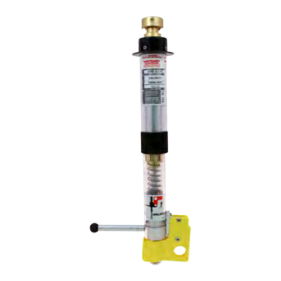
WARNING These instructions are not intended to replace or be a substitute for proper safety training procedures. Failure to select the proper tool in regards to minimum system requirements can result in death, grievous personal injury and or equipment damage. Circuit Restrictions The BREAK-SAFE should not be used if the maximum voltage and/or amperage rating... - Page 4 Components Floating Head Duckbill Head Conductor Hook Yellow Internal Safety Yellow Tube Lock Brass Contacts Load Pick-up Trigger (located under Lock) Conductor Bar Load Break Ring (should rotate freely) B-01031 USBS Manual (11-9-15)
- Page 5 WARNING Only trained and qualified personnel should operate, inspect and maintain this equipment. WARNING The BREAK-SAFE is not waterproof. Do not use the BREAK-SAFE ® ® wet conditions. If inclement weather is expected after installation, cover tool with an approved insulating rubber blanket. WARNING Carefully inspect the tool prior to each use.
-
Page 6: Operation
Operation Prepare the Tool for use Refer to the laminated Field Inspection Procedure card before each use. Place the BREAK-SAFE in the UNLOCK Position (FIGURE 1) by lifting the Yellow ® Safety Lock to gain access to the Load Break Ring. Pull the Load Break Ring until the tool locks in the open tool position (the internal yellow tube is visible). - Page 7 18. If the SOURCE SIDE circuit is to remain energized while work is done, move the jumper cable to the conductor bar of a Utility Solutions Jumper-T (USJT-001/2) or equivalent device (FIGURE 7). This will create a visible gap using rated insulation.
-
Page 8: Operational Life
® either a Heat Run Test or a Resistance Test. Both are done by using the Utility Solutions Grounds Tester (USGT-600) or equivalent device. This test procedure, in addition to the in-field routine maintenance test procedure, will ensure the BREAK-SAFE meets factory ®...