Table of Contents
Advertisement
Quick Links
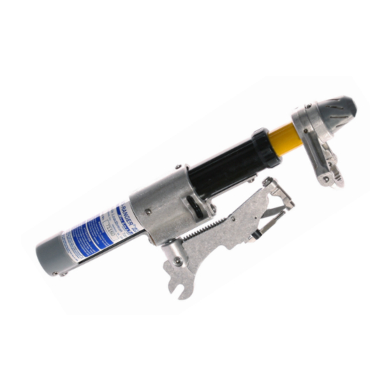
LOAD-RANGER
USLR-XLT-1 Up To 27 kV Load Break Tool
USLR-XLT-2 27 kV - 38 kV Load Break Tool
Contents
Phone
(828)323-8914
Fax
(828)323-8410
sales@utilitysolutionsinc.com
Email
www.utilitysolutionsinc.com
Web
101 33
Street Drive SE · Hickory, NC 28602
rd
Maintenance Manual
B-01286 USLR-XLT Maintenance Manual (11-25-19)
XLT Load Break Tool
®
3
3
4
7
9
10
11
12
13
Advertisement
Table of Contents

Related Manuals for Utility Solutions LOAD-RANGER XLT Series


Summary of Contents for Utility Solutions LOAD-RANGER XLT Series
-
Page 1: Table Of Contents
Maintenance Manual B-01286 USLR-XLT Maintenance Manual (11-25-19) LOAD-RANGER XLT Load Break Tool ® USLR-XLT-1 Up To 27 kV Load Break Tool USLR-XLT-2 27 kV - 38 kV Load Break Tool Contents Overview Tools, Parts, and Supplies Components and Assemblies Disassembly Procedure Probe Shaft Inspection and Cleaning Yellow Tube &... -
Page 3: Overview
Overview Utility Solutions suggests following the maintenance procedure outlined in this manual every 1,500- 2,000 operations. However, a maintenance schedule should not solely depend on the number of operations. -
Page 4: Components And Assemblies
Components and Assemblies P-00484 XLT Repair Fastener Kit (2nd Gen) (Includes all necessary fasteners, B-01073 Loctite, B-01274 Contact Grease and C-01080 Split “O” Ring) B-00159 LOAD BREAK TOOL B-00856 LOCTITE 425 (20 GRAM FIBERGLASS CLEANER / WAX CONTAINER) (16 oz Container) C-00498 XLT THREADED PIN PLUG C-00497 XLT GUIDE PIN C-00509 XLT ARC SHIM... - Page 5 C-00519 XLT SHORT C-00517 XLT FEMALE CONTACT CONDUCTOR PATH C-00520 XLT-1 LONG C-00524 XLT END CAP (MOLDED) CONDUCTOR PATH C-00528 XLT-1 SPACER C-00539 XLT EXTENDED HOOD C-00554 XLT ARC SNUFFER C-00541 XLT-2 LONG CONDUCTOR PATH C-00558 XLT-2 SPACER B-01286 USLR-XLT Maintenance (11-25-19)
- Page 6 P-00048 XLT-1 YELLOW TUBE P-00044 XLT MUFFLER CAP ASSEMBLY ASSEMBLY P-00052 XLT OVERHEAD ARM P-00049 XLT-1 PROBE SHAFT ASSEMBLY ASSEMBLY P-00323 XLT-1 BLACK TUB / CAN P-00055 XLT PADMOUNT ARM ASSEMBLY ASSEMBLY P-00447 XLT-2 YELLOW TUBE P-00822 XLT COUNTER ASSEMBLY ASSEMBLY P-00449 XLT-2 PROBE SHAFT P-00452 XLT-2 BLACK TUB / CAN...
-
Page 7: Disassembly Procedure
Disassembly Procedure 1. Using a #2 Phillips Screwdriver remove the two 10-24 x 1/2” Fillister Head Machine Screw w/ Patch (B-01072) that fasten the XLT Muffler Assembly (P-00044) to the Yellow Tube Assembly (P-00048 XLT-1 or P-00447 XLT-2). 2. Remove the XLT Muffler Assembly (P-00044), XLT Female Contact (C-00517), and the XLT Arc Shim (C-00509). - Page 8 6. Unscrew the Black External Gasket (C-00513) and remove the combined Yellow Tube & Probe Shaft Assemblies. The use of a Channel Lock Pliers may be necessary to unthread the Black External Gasket (C-00513). It may require tapping the sides of the Black External Gasket to loosen the threadlocker prior to unthreading.
-
Page 9: Probe Shaft Inspection And Cleaning
Probe Shaft Inspection and Cleaning Ensure the white molded probe remains clean and free of oils, greases etc. 1. Verify the Pink Arc Snuffers (C-00554), two each for the XLT-1 and 4 each for the XLT- 2, are not cracked, chipped or otherwise damaged. Replace if necessary. 2. -
Page 10: Yellow Tube & Components Inspection And Cleaning
Yellow Tube & Components Inspection and Cleaning Ensure the Arc Tubes remain clean and free of oils, greases etc. 1. Use an all purpose very fine nylon mesh sanding pad to remove surface soot deposits on the XLT Internal Female Contact (C-00517). 2. -
Page 11: Overhead Arm Assembly Inspection And Cleaning
Overhead Arm Assembly Inspection and Cleaning 1. Inspect the Overhead Arm Assembly (P-00052) for damage and proper movement. The assembly should smoothly swing 30 degrees from center in both directions and return to center when released. Overhead Arm Assembly (P-00052) Clip Assembly (P-00031) XLT Clip Post... -
Page 12: Black Tube Assembly & Conductor Path Inspection And Cleaning
2. Apply a small amount of Loctite 263 (B-01073) to the 1/4”-20 x 7/8” Cup point SHSS (B-01268) and fasten using a 1/8” Allen wrench. Continue tightening until the Overhead Arm Assembly (P-00052) can support itself in the upright position. 3. -
Page 13: Reassembly Procedure
Reassembly Procedure 1. Install a XLT Stop Bar (C-00507) with the beveled edge facing toward the Can/Arm Assembly then set the Short Conductor Path (C-00519) in place. 2. Attach the Short Conductor Path (C-00519) to the XLT Stop Bar (C-00507) using a 10-24 x 5/16”... - Page 14 6. Insert the Pink Arc Snuffers (C-00554) into the Yellow Tube assembly, pushing them down until they stop. Two Snuffers for the XLT-1 and four snuffers for the XLT-2. 7. Reinsert the Yellow Tube / Probe Shaft Assembly within the tool. Thread the Black External Gasket (C-00513) onto the Black Tube Assembly.
- Page 15 9. Attach a new Slit “O” Ring (C-01080) around the XLT Guide Pin (C-00497), apply a small amount of Contact Grease (B-01274) to the portion of the Guide Pin (C-01080) that is pressed into the Yellow Tube Assembly. Use a 6LN Needle Nose Vise Grip to install the assembly into the Yellow Tube Assembly.
- Page 16 13. Utilize a standard voltmeter to check continuity (reading Ohms). Attach or hold one lead of the voltmeter to the Hook Loop of the tool. Hold or attach the other lead to the XLT Arm Assembly. When the tool is in the closed position you should measure approximately zero Ohms resistance.