
Related Manuals for Onkyo A-9130


Summary of Contents for Onkyo A-9130
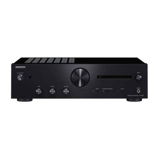
- Page 1 Before use INTEGRATED AMPLIFIER A-9130 Preparations Instruction Manual Basic Operations Others Fr Es...
-
Page 2: Table Of Contents
Connecting players (DIGITAL IN connection) ..9 Connecting players (LINE IN connection) ..10 Connecting players (Turntable connection) ..10 Connecting with Onkyo RI Components ...11 Using this unit as a power amplifier ....12 Power Cord Hookup.......... 12 Setup ..............13 1. -
Page 3: Safety Information
It can also reduce the life or WEEE performance of batteries. http://www.onkyo.com/manual/weee/weee.pdf Risk of explosion if battery is replaced by an incorrect type. Risk of explosion If disposal of a battery into fire or a hot oven, or mechanically crushing or cutting of a battery. -
Page 4: Part Names
Before use Part Names Front Panel 1. Í ON/STANDBY button 2. Remote control sensor: Receives signals from the remote controller. 0 The signal range of the remote controller is within about 16y/5 m, at an angle of 20°... -
Page 5: Rear Panel
1. RI REMOTE CONTROL jack: This jack is for linking when you connect an Onkyo CD player, tuner, network audio player, or RI dock that has an RI (“Remote Interactive”) jack. ( p11) 2. DIGITAL IN COAXIAL D1/DIGITAL IN OPTICAL D2 jacks: Input digital audio signals from a playback device with a digital coaxial cable or digital optical cable. -
Page 6: Remote Controller
Before use Remote Controller Operating this unit 1. Í button: Sets this unit to On or Standby. 2. Cursors (D/C/B/A), ENTER button: Select the item with the cursors and press ENTER to confirm. 3. VOLUME buttons 4. INPUT(D/C) buttons: Switches the input source to be played. - Page 7 Before use Operating other components You can operate Onkyo CD players, tuners, network audio players, and RI docks with the remote controller of this unit. ∫ Operating an Onkyo CD player ∫ Operating an Onkyo tuner, network audio player, or RI dock ...
-
Page 8: Preparations
Preparations Connections Connecting speakers a Speaker Cable 1/2”~5/8” (12~15 mm) Right Left (Note) Speaker Impedance Connect speakers with an impedance of 4 ≠ to 16 ≠. Setup: You have to change the setting on this unit if any of the connected speakers have 4 ≠ or more to less than 8 ≠ impedance. -
Page 9: Connecting A Powered Subwoofer
DIGITAL IN COAXIAL D1 jack. Alternatively, use a Digital subwoofer. optical cable to connect a player to the DIGITAL IN OPTICAL D2 jack. Refer to "Connecting with Onkyo RI Components" ( p11) to use the RI function. 0 Only PCM audio is supported for input through the DIGITAL IN OPTICAL/COAXIAL jacks. -
Page 10: Connecting Players (Line In Connection)
Use an Analog audio cable to connect a player to one of the terminal. With some turntables, connecting the ground wire LINE IN 1/2/3/4/5 jacks. Refer to "Connecting with Onkyo RI may cause hum, in which case it should be disconnected. -
Page 11: Connecting With Onkyo Ri Components
0 The RI feature on this unit supports Onkyo CD players, tuners, network audio players, and RI docks only. It does not work properly with other devices such as MD recorders. -
Page 12: Using This Unit As A Power Amplifier
Preparations Using this unit as a power amplifier Power Cord Hookup a Analog Audio Cable a Power Cord This model includes a removable power cord. The power Pre-amplifier cord must be connected only after all other connections are completed. Make sure you first connect the power cord to AC INLET terminal of the unit and then connect to the outlet. -
Page 13: Setup
Preparations Setup Turn on the power of the unit Remote controller preparations Match the polarity when inserting the batteries. Press Í ON/STANDBY on this unit or Í on the remote controller. -
Page 14: Speaker Impedance Settings
Preparations Speaker impedance settings SETUP Depending on the speakers you connect, you may need to change the speaker impedance setting on this unit. Refer to the page describing speaker connection ( p8) and do the following procedures if the change is required. 1. -
Page 15: Ri Function Settings
Preparations RI function settings SETUP When connecting an Onkyo CD player or tuner to the RI REMOTE CONTROL jack on this unit ( p11) and using the RI function, you need to make RI function settings. 1. Press SETUP on the remote controller. -
Page 16: Basic Operations
Basic Operations Playback Switching input and adjusting the volume VOLUME INPUT Perform the following procedure when the unit is on. 1. Press INPUTD/C on the remote controller to switch to the input with the same name as the jack to which you have connected the player. -
Page 17: Subwoofer Output Settings
Basic Operations Subwoofer output settings SETUP This unit enables you to choose the subwoofer output mode, with the choices being "Auto" (default setting), "On", and "Off". Auto : The subwoofer signal is not output when the DIRECT function ( p18) is on. : The subwoofer signal is always output. -
Page 18: Using The Direct Function
Basic Operations Using the Direct Function Adjusting the sound quality and balance DIRECT PM BASS When you turn the DIRECT feature on (default value), the unit bi-passes the tone control circuits that adjust the bass PHASE MATCHING BASS and treble, taking the shortest route which favors sound Turning the PHASE MATCHING BASS function on quality. -
Page 19: Switching The Unit To Power Amplifier Mode
Basic Operations 1. Turn the TREBLE -/+ controller to enhance or moderate “Speaker impedance settings” ( p14) / “RI function the treble. settings” ( p15) / “Switching input and adjusting the volume” ( p16) / “Subwoofer output settings” ( p17) / “Adjusting the sound quality and balance”... -
Page 20: Others
Others Useful functions Setting auto standby SETUP When automatic standby is on (default value), the unit automatically switches to standby mode after 20 minutes of no audio input without any operations. 1. Press SETUP on the remote controller. 0 If this unit is set to be used as a power amplifier, the SETUP button will not work. -
Page 21: Troubleshooting
Others Troubleshooting speaker wires are not touching each other or the back Before starting the procedure panel of the unit, then turn the unit on again. If this unit does not turn on, immediately unplug the power cord from the wall outlet and contact your dealer. Problems may be solved by simply turning the power on/off 0 The protective circuit function may have been activated or disconnecting/connecting the power cord, which is easier... - Page 22 Others 0 Make sure the speakers are connected correctly. ( p8) ∫ Noise can be heard 0 Using cable ties to bundle analog audio cables, power cords, speaker cables, etc. may degrade the audio performance, Do not bundle cords. 0 An audio cable may be picking up interference. Try repositioning your cables.
-
Page 23: Specifications
Others Specifications Amplifier (Audio) section Audio Inputs Rated Output Power (IEC) Digital 2 ch k 60 W at 4 ohms, 20 Hz-20 kHz, 2 ch driven of OPTICAL (D2) 0.5% THD Maximum Fs: 192 kHz 2 ch k 76 W at 4 ohms, 1 kHz, 2 ch driven of 0.9% THD COAXIAL (D1) 2 ch k 30 W at 8 ohms, 20 Hz-20 kHz, 2 ch driven of Maximum Fs: 192 kHz...
Need help?
Do you have a question about the A-9130 and is the answer not in the manual?
Questions and answers