
Related Manuals for Goulds Pumps SMVT


Summary of Contents for Goulds Pumps SMVT
- Page 1 INSTRUCTION MANUAL IOMGWSMVTR05-EN Model SMVT INSTALLATION, OPERATION AND MAINTENANCE MANUAL...
- Page 2 SMVT Installation, Operation and Maintenance Manual...
-
Page 3: Table Of Contents
Model number and serial number may be found on the tag mounted to the motor adapter. Model Number ___________________________ Serial Number ____________________________ Dealer ___________________________________ Dealer phone number ______________________ Date of purchase __________________________ Date of installation ________________________ SMVT Installation, Operation and Maintenance Manual... -
Page 4: Introduction And Safety
Introduction Description This manual provides instructions for the Installation, Operation and Maintenance of the Goulds Water Technology Model SMVT pumps. This manual covers the standard product plus common options that are available. Requirement This manual must be read and understood before installation and start-up. Goulds Water... - Page 5 1. Follow local laws and regulations regarding recycling if the unit or parts are accepted by an authorized recycling company. 2. If the first guideline is not applicable then return the unit or parts to the nearest Goulds Water Technology representative. SMVT Installation, Operation and Maintenance Manual...
- Page 6 Single-phase motors have built-in overload protectors. • Never start a pump without the proper priming. • Never run a pump below the minimum rated flow or with any suction or discharge valve closed. SMVT Installation, Operation and Maintenance Manual...
- Page 7 • Beware of the risk of a sudden start if the product is used with an automatic level control. • Beware of the starting jerk, which can be powerful. • Rinse the components in water after disassembling the pump. • Do not exceed the maximum working pressure of the pump. SMVT Installation, Operation and Maintenance Manual...
- Page 8 Goulds Water Technology are essential for compliance. The use of other parts can invalidate any claims for warranty or compensation and explosion-proof approvals. Warranty claim For warranty claim, contact your Goulds Water Technology representative. SMVT Installation, Operation and Maintenance Manual...
-
Page 9: Transportation And Storage
Figure 1. DO NOT lift the pump with the motor installed to the pump assembly. Consult the motor manufacturer’s Installation, Operation, and Maintenance manual supplied with your motor for proper handling procedures for the motor assembly. Figure 1: Proper Lifting SMVT Installation, Operation and Maintenance Manual... -
Page 10: Product Description
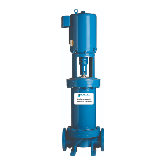
Product Description III. Product Description Description This section provides a general description of the Goulds Water Technology Model SMVT and key engineering specifications. Overview The Goulds Water Technology Model SMVT pumps are surface mounted, multi-stage, vertical turbine pumps. Pump impellers are closed, shaft driven, and held in position by a positive-locking taper collet. - Page 11 215TC 254TC 256TC 256TC 284TSC 3500 284TSC 230/460 286TSC 286TSC 324TSC 324TSC 326TSC 326TSC 364TSC 364TSC 365TSC Electric data is based on Goulds Water Technology choice motors. Other manufacturer’s motors may have different values. SMVT Installation, Operation and Maintenance Manual...
- Page 12 Name Plate Model # The various versions of the SMVT are identified by a product code number on the pump label. This number is also the catalog number for the pump. The meaning of each digit in the product code number is shown in the Appendix. Not all combinations are possible;...
-
Page 13: Installation
When the concrete has dried, tighten nuts to keep the pump firmly in position. Your SMVT pump has been supplied with a rigid base pump body with two feet. The mounting dimensions are shown in Figure 2. - Page 14 6. Move on to the next section; “Installation of Motor to Pump Assembly”. Installation of Motor to Pump Assembly Your SMVT pump has been shipped with the pump assembly and motor disassembled. 1. With an adequately sized crane carefully lower the motor assembly onto the motor adapter located on the top of the pump.
- Page 15 It MUST NOT place piping loads on the pump. 2. Piping should be no smaller than the pump’s suction and discharge connections and kept as short as possible, with minimal fittings to minimize friction losses. SMVT Installation, Operation and Maintenance Manual...
- Page 16 1. Use of elbows close to pump suction should be avoided. There should be a minimum of two pipe diameters of straight pipe between elbow and suction inlet (Reference Figure 8). All elbows should be long-radius. SMVT Installation, Operation and Maintenance Manual...
- Page 17 6. Ensure that the size and minimum submergence over the suction inlet is sufficient to prevent air from entering the pump through a suction vortex. See typical intake piping arrangements in Figures 10-13. SMVT Installation, Operation and Maintenance Manual...
- Page 18 2. Increasers, if used, should be placed between the pump and check valves. 3. Cushioning devices should be used to protect the pump from surges and water hammer if quick closing valves are installed in the system. SMVT Installation, Operation and Maintenance Manual...
- Page 19 Warning: Install an all leg electrical power disconnect switch near the pump. cause death. Warning: Electrical supply MUST match motor’s nameplate specifications. Incorrect voltage can cause fire, damage the motor and void the warranty. SMVT Installation, Operation and Maintenance Manual...
- Page 20 1. Connect the BLACK wire to the BLACK motor lead. 2. Connect the WHITE wire to the WHITE motor lead. 3. Connect the GREEN wire to the GREEN motor lead. Three Phase Motors See Figure 15 for three-phase wiring diagrams. SMVT Installation, Operation and Maintenance Manual...
- Page 21 DO NOT confuse the rotation direction with the flow arrows cast into the pump body. The rotation arrow is cast into the coupling. • To reverse three phase motor rotation, have a qualified technician interchange any two of the three power supply leads. SMVT Installation, Operation and Maintenance Manual...
-
Page 22: Commissioning, Startup, Operation And Shutdown
Never start the pump until it has been properly primed. Several different methods of priming can be used, depending upon type of installation and service involved. Warning: SMVT pumps are not self priming and must be fully primed at all times during operation. Loss of prime can lead to excessive heat and severe damage to the pump and seal. - Page 23 Caution: Driver may overload if the pumpage specific gravity (density) or viscosity is greater than originally assumed or the rated flow rate is exceeded. Caution: Always operate the pump at or near the rated conditions to prevent damage resulting from cavitation or recirculation. SMVT Installation, Operation and Maintenance Manual...
- Page 24 Warning: When handling hazardous and or toxic fluids, proper personal protective equipment should be worn. If pump is being drained, precautions must be taken to prevent physical injury. Pumpage must be handled and disposed of in conformance with applicable environmental regulations. SMVT Installation, Operation and Maintenance Manual...
-
Page 25: Maintenance
Otherwise, a system inspection should be done. Motor Maintenance Consult the motor manufacturer’s Installation, Operation, and Maintenance manual supplied with your motor for proper maintenance procedure and schedule. SMVT Installation, Operation and Maintenance Manual... - Page 26 Note: Before disassembling the pump for overhaul, ensure all replacement parts are available. 1. Close all necessary suction and discharge valves. 2. Drain the liquid from the pump by removing the lower drain plugs and the upper vent plug. See Figure 17. SMVT Installation, Operation and Maintenance Manual...
- Page 27 The pump shaft should be completely dry before moving on to the next step. 10. To install the new mechanical seal assembly, carefully slide it down the pump shaft until the gland contacts the mounting surface on the top of the seal housing. SMVT Installation, Operation and Maintenance Manual...
- Page 28 20. Inspect run out of the shaft between the bottom of the coupling and the mechanical seal as shown in Figure 20a. If the run out exceeded 0.005”, the coupling must be adjusted. It is usually most effective to adjust the four bolt section of the coupling. SMVT Installation, Operation and Maintenance Manual...
- Page 29 11. Very lightly tighten the (2) socket head cap screws on the pump end of the coupling (refer to Figure 22). Tighten the coupling evenly; ensure that the coupling is symmetrical on both the pump and motor shafts. Do NOT torque the cap screws in this step. SMVT Installation, Operation and Maintenance Manual...
- Page 30 19. Follow the instructions in “Section IV . Installation” to properly wire the motor. 20. Follow the instructions in “Section V . Commissioning, Startup, Operation, and Shutdown” for the proper procedures to restart the pump. SMVT Installation, Operation and Maintenance Manual...
- Page 31 4. Loosen the set screws on the seal collar. 5. Disassemble the coupling by removing the (6) socket head screws. Remove the dowel pin on the pump shaft. See Figure 25. Retain bolts and dowel pin for reassembly. Figure 25: Motor Coupling SMVT Installation, Operation and Maintenance Manual...
- Page 32 13. Torque the bolts in the pattern shown in Figure 27. See the “Engineering Data” section on page 8 of this manual for the proper torque value. Figure 27: Bowl Bolts Torque Pattern SMVT Installation, Operation and Maintenance Manual...
- Page 33 29. Take care to make sure that the pump and motor shafts are clean; they should be free of all burrs, oil, and grease. Both the pump and motor shafts should be completely dry before moving on to the next step. SMVT Installation, Operation and Maintenance Manual...
- Page 34 38. Tighten the set screws on the seal gland. See the “Engineering Data” section on page 8 of this manual for the proper torque value. 39. Install the (2) coupling guards. SMVT Installation, Operation and Maintenance Manual...
-
Page 35: Troubleshooting
11. System head too high. 12. NPSHa too low-excessive suction lift or losses. 13. Discharge head too low-excessive flow rate. 14. Fluid viscosity, specific gravity too high. 15. Worn bearing. 16. Pump, motor or piping loose. SMVT Installation, Operation and Maintenance Manual... -
Page 36: Appendix
SMVT Product Line Numbering System The various versions of the SMVT line are identified by a product code number on the pump label. This number is also the catalog number for the pump. The meaning of each digit in the product code number is shown below. - Page 37 Guard – Motor Support Pipe Plug Hex Screws – Motor Support Mechanical Seal Hex Screws – Seal Coupling Cap Screws – Coupling Lock Washers – Coupling Dowel Pin – Coupling Motor Hex Screws – Motor Seal Plate SMVT Installation, Operation and Maintenance Manual...
- Page 38 Notes Notes SMVT Installation, Operation and Maintenance Manual...
- Page 39 Notes Notes SMVT Installation, Operation and Maintenance Manual...
-
Page 40: Warranty
Company or supplier furnished manuals. Xylem Inc. P.O. Box 5487 Lubbock, TX 79408 Phone: (806) 763-7867 Fax: (800) 453-4749 www.gouldswatertechnology.com Goulds is a registered trademark of Goulds Pumps, Inc. and is used under license. © 2017 Xylem Inc. IOMGWSMVTR05-EN August 2017...
Need help?
Do you have a question about the SMVT and is the answer not in the manual?
Questions and answers