Table of Contents
Advertisement
PS4000 and PS5000
Touchscreen Programmable Thermostat
Installation and Owners Manual
www.robertshaw.com
©2016 Robertshaw
01/16 – 352-00244-001
Advertisement
Table of Contents

Subscribe to Our Youtube Channel
Related Manuals for Uni-Line Perfect Sense PS4000


Summary of Contents for Uni-Line Perfect Sense PS4000
- Page 1 PS4000 and PS5000 Touchscreen Programmable Thermostat Installation and Owners Manual www.robertshaw.com ©2016 Robertshaw 01/16 – 352-00244-001...
-
Page 2: Important Safety Information
IMPORTANT SAFETY INFORMATION WARNING: ELECTRICAL SHOCK HAZARD – Turn off power at the main power source by unscrewing fuse or switching circuit breaker to the OFF position before installing, removing, or cleaning this thermostat. WARNING: FIRE AND ELECTRIC SHOCK HAZARD – This device should be installed by a qualified service technician with due regard for safety as improper installation could result in a fire and electric shock hazard. -
Page 3: Table Of Contents
PS4000/PS5000 Touchscreen Programmable Thermostat Contents Application/Features........................2 Specifications.........................4 Installation..........................13 Wiring.............................17 Power the Thermostat......................34 Installer Set-up........................47 Installer System Test......................58 Owners Manual........................61 Programming .........................67 Troubleshooting........................94... - Page 4 PS4000/PS5000 Touchscreen Programmable Thermostat PRODUCT DATA APPLICATION The PS4000 Touchscreen Programmable Thermostat is an effortless, 7-Day programmable thermostat that provides universal system compatibility, precise comfort control and is easy to program. The PS4000 Thermostat provides temperature control for gas, oil, electric, millivolt and heat pump for 1 heat /1 cool systems including dual fuel operation.
- Page 5 PS4000/PS5000 Touchscreen Programmable Thermostat FEATURES ·Large, clear display with backlight shows current temperature, set temperature and thermostat in the dark. ·Menu-driven programming make set-up effortless. ·Beautiful ergonomic design is smart and sophisticated. ·Touchscreen interaction. ·Real-time clock keeps time during power failures and automatically updates to daylight savings.
-
Page 6: Specifications
PS4000/PS5000 Touchscreen Programmable Thermostat SPECIFICATIONS Thermostat Description: Powering methods 24V AC common wire or AA batteries ·Gas, oil or electric heat with air conditioning System types ·Warm air, hot water, high-efficiency furnaces, heat PS4000 (1 Heat/1 Cool) pumps, steam and gravity PS5000 (3 Heat/2 Cool) ·Heat only includes power to open and power to close zone valves and normally-open... - Page 7 PS4000/PS5000 Touchscreen Programmable Thermostat Electrical Ratings: Terminal Voltage (50/60 Hz) Running Current W Heating 20 - 30V AC 1 Amp max. W Heating (Power pile) 750 mV DC 100 mAmp Y Cooling 20 - 30V AC 1 Amp max. G Fan 20 - 30V AC 1 Amp max.
- Page 8 PS4000/PS5000 Touchscreen Programmable Thermostat Operating Relative Humidity (Non-condensing): 5% to 90% Cycle Rates (at 50% Load): Heating: Selectable 1 - 12 cycles per hour Cooling: Selectable 1 - 6 cycles per hour Clock Accuracy: +/- 1 minute per month Batteries: Two replaceable AA alkaline batteries will power the thermostat when 24V AC common is not used.
- Page 9 PS4000/PS5000 Touchscreen Programmable Thermostat Cool Indication: Touchscreen Thermostats show "Cool On" on the screen when Cool is activated. Heat Indication: Touchscreen Thermostats show "Heat On" on the screen when Heat is activated. Calibration: Touchscreen Thermostats are factory-calibrated and require no field calibration. Auxiliary Heat Indication: PS5000 Touchscreen Thermostats show "Aux Heat On"...
- Page 10 PS4000/PS5000 Touchscreen Programmable Thermostat Nomenclature: Application Series System Stages PS4000 1 Heat / 1 Cool PS4000 - Standard PS5000 3 Heat / 2 Cool PS5000 - Standard Mounting Means: Touchscreen Thermostat: Mounts directly on the wall in the living space using mounting screws and anchors provided.
- Page 11 PS4000/PS5000 Touchscreen Programmable Thermostat 1.235 in.(30.60mm) 5.98 in.(152mm) Figure 1. Touchscreen Thermostat dimensions in inches. (mm).
- Page 12 PS4000/PS5000 Touchscreen Programmable Thermostat 1.77 in.(45mm) 1.51 in.(38.5mm) 0.84 in .(21.5mm) Figure 2. Touchscreen Thermostat Back Case dimensions in inches. (mm).
- Page 13 PS4000/PS5000 Touchscreen Programmable Thermostat 1.82 in.(46.3mm) 1.49 in.(38mm) 0.08 in.(2mm) 1.56 in .(39.7mm) 0.44 in .(11.2mm) 0.24 in.(6.2mm) Figure 3. Outdoor Sensor Mounting Clip dimensions in inches. (mm).
- Page 14 PS4000/PS5000 Touchscreen Programmable Thermostat 5.35 in.(136mm) 3.29 in.(83.5mm) 0.85 in .(21.5mm) Figure 4. Cover Plate dimensions in inches. (mm).
-
Page 15: Installation
PS4000/PS5000 Touchscreen Programmable Thermostat INSTALLATION When Installing this Product 1. Read these instructions carefully. Failure to follow the instructions can damage the product or cause a hazardous condition. 2. Check the ratings given in the instructions to make sure the product is suitable for your application. - Page 16 PS4000/PS5000 Touchscreen Programmable Thermostat 5 FEET (1.5 METERS) Figure 5. Selecting thermostat location.
- Page 17 PS4000/PS5000 Touchscreen Programmable Thermostat Installing Wall Plate CAUTION Electrical Hazard. Can cause electrical shock or equipment damage. Disconnect power before wiring. The thermostat can be mounted horizontally on the wall 1. Position and level the wall plate (for location only). 2.
- Page 18 PS4000/PS5000 Touchscreen Programmable Thermostat WALL WIRES THROUGH WALL AND WIRE SLOT WALL ANCHORS MOUNTING HOLES(2) MOUNTING SCREWS(2) Figure 6. Mounting wall plate.
-
Page 19: Wiring
PS4000/PS5000 Touchscreen Programmable Thermostat WIRING (FIGURE 9-21) All wiring must comply with local electrical codes and ordinances. 1. Select the set of terminal identifications (Table 1) that corresponds with system type (conventional or heat pump in Figure 7). 2. Loosen the screws for the appropriate system type selected; see Table 1. See Table 2 for terminal designation descriptions. - Page 20 PS4000/PS5000 Touchscreen Programmable Thermostat Table 1. Selecting Terminal Identifications for System Type. Wall Plate Terminal Wiring Diagram Model System Type Identifications Figures PS4000 Standard Heat/Cool Conventional 9, 10 PS5000 PS4000 o i t PS5000 PS4000 Heat Only with Fan Conventional PS5000 PS4000 Heat Only Power to open and power...
- Page 21 PS4000/PS5000 Touchscreen Programmable Thermostat Figure 8. Inserting wires in terminal block. IMPORTANT: Use 18 gauge thermostat wire.
- Page 22 PS4000/PS5000 Touchscreen Programmable Thermostat Table 2. Terminal Designation Descriptions. Model Power for cooling--connect to secondary side of cooling system PS4000/PS5000 RC (see Note 1) transformer Power for heating--connect to secondary side of heating system PS4000/PS5000 R (see Note 1) transformer C (see Note 2) Common wire from secondary side of cooling system transformer PS4000/PS5000...
- Page 23 PS4000/PS5000 Touchscreen Programmable Thermostat OPTIONAL 24V AC COMMON OUTDOOR/INDOOR CONNECTION TEMPERATURE COMPRESSOR SENSOR FAN RELAY CONTACTOR HEAT RELAY S1 S2 C R RC W W2 Y2 Y G CONVENTIONAL 1. POWER SUPPLY. PROVIDE DISCONNECT MEANS AND OVERLOAD PROTECTION AS REQUIRED. 2.
- Page 24 PS4000/PS5000 Touchscreen Programmable Thermostat OPTIONAL 24V AC COMMON OUTDOOR/INDOOR CONNECTION TEMPERATURE SENSOR FAN RELAY COMPRESSOR CONTACTOR HEAT RELAY S1 S2 C R RC W W2 Y2 Y G CONVENTIONAL 1. POWER SUPPLY. PROVIDE DISCONNECT MEANS AND OVERLOAD PROTECTION AS REQUIRED. 2.
- Page 25 PS4000/PS5000 Touchscreen Programmable Thermostat OPTIONAL OUTDOOR/INDOOR 24V AC TEMPERATURE COMMON SENSOR HEAT RELAY CONNECTION S1 S2 C R RC W W2 Y2 Y G CONVENTIONAL 1. POWER SUPPLY. PROVIDE DISCONNECT MEANS AND OVERLOAD PROTECTION AS REQUIRED. 2. FACTORY INSTALLED JUMPER. 3.
- Page 26 PS4000/PS5000 Touchscreen Programmable Thermostat OPTIONAL OUTDOOR/INDOOR 24V AC TEMPERATURE COMMON SENSOR CONNECTION HEAT RELAY FAN RELAY S1 S2 C R RC W W2 Y2 Y G CONVENTIONAL 1. POWER SUPPLY. PROVIDE DISCONNECT MEANS AND OVERLOAD PROTECTION AS REQUIRED. 2. FACTORY INSTALLED JUMPER. 3.
- Page 27 PS4000/PS5000 Touchscreen Programmable Thermostat MOTOR OR VALVE OUTDOOR/INDOOR TEMPERATURE SENSOR S1 S2 C R RC W W2 Y2 Y G CONVENTIONAL 1. POWER SUPPLY. PROVIDE DISCONNECT MEANS AND OVERLOAD PROTECTION AS REQUIRED. 2. FACTORY INSTALLED JUMPER. 3. OPTIONAL OUTDOOR OR INDOOR REMOTE SENSOR. AVAILABLE ON SELECT MODELS. WIRES MUST HAVE A CABLE SEPARATE FROM THE THERMOSTAT CABLE.
- Page 28 PS4000/PS5000 Touchscreen Programmable Thermostat OPTIONAL OUTDOOR/INDOOR 24V AC TEMPERATURE COMMON NORMALLY OPEN SENSOR CONNECTION ZONE VALVE S1 S2 C R RC W W2 Y2 Y G CONVENTIONAL 1. POWER SUPPLY. PROVIDE DISCONNECT MEANS AND OVERLOAD PROTECTION AS REQUIRED. 2. FACTORY INSTALLED JUMPER. 3.
- Page 29 PS4000/PS5000 Touchscreen Programmable Thermostat OPTIONAL 24V AC COMMON OUTDOOR/INDOOR CONNECTION TEMPERATURE COMPRESSOR SENSOR FAN RELAY CONTACTOR S1 S2 C R RC W W2 Y2 Y G CONVENTIONAL 1. POWER SUPPLY. PROVIDE DISCONNECT MEANS AND OVERLOAD PROTECTION AS REQUIRED. 2. FACTORY INSTALLED JUMPER. 3.
- Page 30 PS4000/PS5000 Touchscreen Programmable Thermostat OUTDOOR/INDOOR TEMPERATURE HEAT RELAY 2 SENSOR FAN RELAY COOL RELAY 2 HEAT RELAY 1 COOL RELAY 1 S1 S2 C R RC W W2 Y2 Y G CONVENTIONAL PS5000 ONLY. 1. POWER SUPPLY. PROVIDE DISCONNECT MEANS AND OVERLOAD PROTECTION AS REQUIRED. 2.
- Page 31 PS4000/PS5000 Touchscreen Programmable Thermostat OUTDOOR/INDOOR TEMPERATURE HEAT RELAY 2 SENSOR FAN RELAY COOL RELAY 2 HEAT RELAY 1 COOL RELAY 1 S1 S2 C R RC W W2 Y2 Y G CONVENTIONAL PS5000 ONLY 1. POWER SUPPLY. PROVIDE DISCONNECT MEANS AND OVERLOAD PROTECTION AS REQUIRED. 2.
- Page 32 PS4000/PS5000 Touchscreen Programmable Thermostat S1 S2 C R RC W W2 Y2 Y G S1 S2 C R RC E L Y2 Y G O/B AUX HEAT PUMP CHANGEOVER COMPRESSOR VALVE RELAY FAN RELAY OPTIONAL OUTDOOR/INDOOR TEMPERATURE 24V AC SENSOR COMMON CONNECTION 1.
- Page 33 PS4000/PS5000 Touchscreen Programmable Thermostat S1 S2 C R RC W W2 Y2 Y G S1 S2 C R RC E L Y2 Y G O/B AUX HEAT PUMP COMPRESSOR 2 CHANGEOVER COMPRESSOR 1 VALVE OUTDOOR/INDOOR OPTIONAL FAN RELAY TEMPERATURE 24V AC COMMON SENSOR CONNECTION...
- Page 34 PS4000/PS5000 Touchscreen Programmable Thermostat S1 S2 C R RC W W2 Y2 Y G S1 S2 C R RC E L Y2 Y G O/B AUX HEAT PUMP CHANGEOVER VALVE EMERGENCY HEAT 2 RELAY HEAT RELAY (AUXILIARY HEAT) OUTDOOR/INDOOR TEMPERATURE EQUIPMENT SENSOR COMPRESSOR...
- Page 35 PS4000/PS5000 Touchscreen Programmable Thermostat S1 S2 C R RC W W2 Y2 Y G S1 S2 C R RC E L Y2 Y G O/B AUX HEAT PUMP CHANGEOVER VALVE EMERGENCY HEAT 2 RELAY HEAT RELAY (AUXILIARY HEAT) OUTDOOR/INDOOR TEMPERATURE EQUIPMENT SENSOR COMPRESSOR 2...
-
Page 36: Power The Thermostat
PS4000/PS5000 Touchscreen Programmable Thermostat POWER THE THERMOSTAT You can choose from three methods to power the thermostat. · Batteries only (AA alkaline). · 24V AC common wire only. · 24V AC common wire with battery back-up (AA alkaline). Wiring 24V AC Common ·... -
Page 37: Installing Batteries
PS4000/PS5000 Touchscreen Programmable Thermostat Installing Batteries 1. Install two AA alkaline batteries on the 2. Locate and remove the tab. See Figure 23. back of the thermostat as marked on the thermostat. See Figure 22. REMOVE BATTERIES(2) Figure 22. Installing batteries. Figure 23. - Page 38 PS4000/PS5000 Touchscreen Programmable Thermostat Mount Thermostat to Wall Plate 1. Align the terminal screw blocks with the pins on the back of the thermostat. Push the thermostat straight onto the wall plate until it snaps into place. See Figure 24. WALL PLATE TERMINAL SCREW BLOCK PINS ON BACK OF...
- Page 39 PS4000/PS5000 Touchscreen Programmable Thermostat Locate and Mount Outdoor Temperature Sensor (Optional) Mount the sensor where: ·The settings cannot be tampered with ·There is good air circulation ·It can measure true outdoor ambient temperature ·There is a flat surface ·Maximum distance between outdoor sensor and touchscreen thermostat is 65 ft (20m) See Figure 25.
- Page 40 PS4000/PS5000 Touchscreen Programmable Thermostat Figure 25. Typical locations for Outdoor Sensor.
- Page 41 PS4000/PS5000 Touchscreen Programmable Thermostat CAUTION - OUTDOOR SENSOR Electrical Interference (Noise) Hazard. Can cause erratic system operation. Keep wiring at least one foot away from large inductive loads such as motors, line starters, lighting ballasts and large power distribution panels. Use shielded cable to reduce interference when rerouting is not possible.
- Page 42 PS4000/PS5000 Touchscreen Programmable Thermostat CAUTION - OUTDOOR SENSOR Electrical Shock Hazard. Can cause electrical shock or equipment damage. Disconnect power supply before connecting wiring. Wiring must comply with local and national codes, ordinances and regulations: 1. Wire Outdoor Sensor to S1 and S2 terminals on the thermostat. If leadwire provided is not long enough, you need an extra cable to reach the hole at maximum distance between the outdoor sensor and the touchscreen thermostat is 65 ft (20m).
- Page 43 PS4000/PS5000 Touchscreen Programmable Thermostat WIRING HOLE THROUGH STRUCTURE 1. USE APPROPRIATE MOUNTING MEANS FOR THE TYPE OF STRUCTURE. 2. PLUG WIRING HOLE WITH NON-HARDENING CAULK OR PUTTY. Figure 26. Wire Outdoor Sensor to the thermostat.
- Page 44 PS4000/PS5000 Touchscreen Programmable Thermostat Locate and Mount Remote Indoor Temperature Sensor (Optional) 1. Choose a location (see Figure 27) for mounting the sensor on an inside wall about 5 ft (1.5m) above the floor. 2. Be sure wire distance between sensor and thermostat is less than 19.6 ft (6m). 3.
- Page 45 PS4000/PS5000 Touchscreen Programmable Thermostat 5 FEET 1.5 METERS Figure 27. Typical location for Indoor Sensor.
- Page 46 PS4000/PS5000 Touchscreen Programmable Thermostat Wire Indoor Sensor CAUTION Electrical Interference (Noise) Hazard. Can cause erratic system operation. Keep wiring at least one foot away from large inductive loads such as motors, line starters, lighting ballasts and large power distribution panels. IMPORTANT Erratic temperature readings from a sensor can occur as a result of any of the wiring practices described below.
- Page 47 PS4000/PS5000 Touchscreen Programmable Thermostat CAUTION Electrical Shock Hazard. Can cause electrical shock or equipment damage. Disconnect power supply before connecting wiring. Wiring must comply with local and national applicable codes, ordinances and regulations. 1. Wire Indoor Sensor to S1 and S2 terminals on the thermostat. For an example of general wiring of sensor, see Figure 28 to wire one sensor and Figure 29 to wire multiple sensors.
- Page 48 PS4000/PS5000 Touchscreen Programmable Thermostat S1 S2 C R RC S1 S2 C R RC W W2 Y2 Y G S1 S2 C R RC 1. POWER SUPPLY. PROVIDE DISCONNECT MEANS AND OVERLOAD PROTECTION AS REQUIRED. 2. IF MORE THAN ONE REMOTE SENSOR IS REQUIRED, REFER TO FIGURE 29.
-
Page 49: Installer Set-Up
PS4000/PS5000 Touchscreen Programmable Thermostat INSTALLER SET-UP Follow these steps to enter the Installer 2. Press the two blank keys on either side Set-up: of the center blank key for approximately 1. Press and release the SYSTEM Key. five seconds until screen changes. Room Room Running As SCHED... - Page 50 PS4000/PS5000 Touchscreen Programmable Thermostat 4. See screen below to review how the 3. Release the two blank keys when the thermostat keys are used during Installer screen on the thermostat matches the screen below. Set-up. See Tables 3-5 for the Installer Set-up numbers and settings.
- Page 51 PS4000/PS5000 Touchscreen Programmable Thermostat Table 3. Installer Set-up Menu. NOTE For easier installer set-up, write the selected options in the "INITIAL SETTING RECORD" column. Installer Initial Installer Set-up Set-up Setting Setting Name Number Record Date Select first two digits of current calendar year 0120 It cannot be changed.
- Page 52 PS4000/PS5000 Touchscreen Programmable Thermostat Table 3. Installer Set-up Menu. (CONTINUED) Initial Installer Installer Set-up Setting Set-up Name Record Number Only shown if conventional 0-gas or oil furnace equipment controls fan in Fan Control in system is selected. If heat 0180 heating (factory setting).
- Page 53 PS4000/PS5000 Touchscreen Programmable Thermostat Table 3. Installer Set-up Menu. (CONTINUED) Initial Installer Installer Set-up Setting Set-up Name Number Record 1- 1 CPH used for steam and gravity. Not shown if system 3-3 CPH used for hot water system and high Cycles per hour (CPH) efficiency (90% or better) furnaces.
- Page 54 PS4000/PS5000 Touchscreen Programmable Thermostat Table 3. Installer Set-up Menu. (CONTINUED) Installer Initial Installer Set-up Setting Set-up Name Record Number 3-3 CPH for hot water systems and high PS5000 ONLY efficiency (90% or better) furnaces. Cycles per hour Only shown if 2H/1C or 0270 5-5 CPH for standard fossil fuel forced air (less (CPH) for EMER...
- Page 55 PS4000/PS5000 Touchscreen Programmable Thermostat Table 3. Installer Set-up Menu. (CONTINUED) Installer Initial Installer Set-up Setting Set-up Name Record Number Set to 0 in areas that do 1-daylight savings is on (factory setting). 0330 Daylight Savings not follow daylight 0-daylight savings is off. savings.
- Page 56 PS4000/PS5000 Touchscreen Programmable Thermostat Table 3. Installer Set-up Menu. (CONTINUED) Installer Initial Installer Set-up Set-up Setting Name Number Record PS5000 ONLY. 0-no auxiliary heat lockout. Shown if electric is chosen for 40°F (4.5°C) back-up heat source and outdoor Heat Pump 45°F (7°C) 0360 temperature sensor for control is...
- Page 57 PS4000/PS5000 Touchscreen Programmable Thermostat Table 3. Installer Set-up Menu. (CONTINUED) Initial Installer Installer Set-up Setting Set-up Name Record Number 0-humidifier pad replacement reminder off. PS5000 ONLY. Humidifier Pad 1-90 calendar days. 0510 Replacement 2-180 calendar days. Reminder 3-365 calendar days. UV Lamp 0-UV lamp replacement reminder off.
- Page 58 PS4000/PS5000 Touchscreen Programmable Thermostat Table 3. Installer Set-up Menu. (CONTINUED) Initial Installer Installer Set-up Set-up Setting Name Number Record 12-12 hour clock (factory setting). 0640 Clock Format 24-24 hour clock. 0-no extended fan operation after call for heat Extended Fan On ends.
- Page 59 PS4000/PS5000 Touchscreen Programmable Thermostat Table 3. Installer Set-up Menu. (CONTINUED) Installer Initial Installer Set-up Set-up Setting Name Number Record 1-less aggressive temperature control Applies to recovery ramp. Temperature (could cause temperature undershoot). Choose 1 if getting temperature Control in 2-Standard temperature control in cooling 0690 overshoot.
-
Page 60: Installer System Test
PS4000/PS5000 Touchscreen Programmable Thermostat INSTALLER SYSTEM TEST For the PS4000, use the Installer System Test to test the W, Y, and L terminals. For the PS5000, use the Installer System Test to test the W, W2, E, AUX, Y, Y2, and L terminals. CAUTION Equipment Damage Hazard. - Page 61 PS4000/PS5000 Touchscreen Programmable Thermostat UP ARROW KEY SYSTEM STAUS SYSTEM TEST ADVANCES TO NUMBER NUMBER NEXT SYSTEM TEST NUMBER DONE DONE KEY DOWN ARROW UP ARROW TURNS THE TURNS THE EXITS INSTALLER SYSTEM TEST SYSTEM OFF SYSTEM ON Figure 30. Review thermostat buttons used during Installer System Test.
- Page 62 PS4000/PS5000 Touchscreen Programmable Thermostat Installer System Tests Table 4. Installer System Test. System Status Number and Description 1-Cool stage 1 and stage 2 turn on. n i l 0-Cool is off. 1-Fan turns on. 0-Fan turns off. PS4000: 1-Heat stage 1 on. 3 - PS4000 0-Heat is off.
-
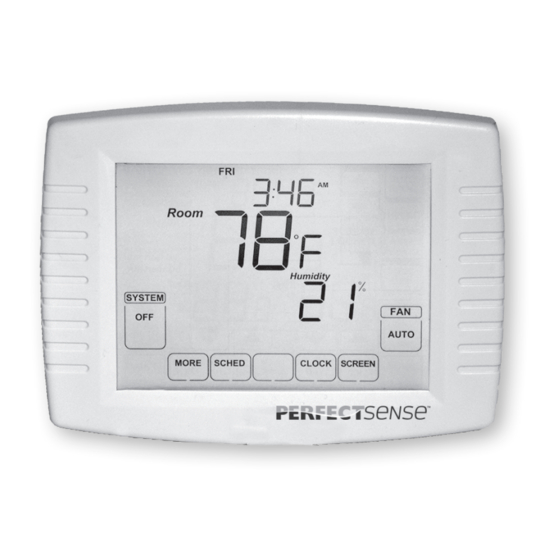
Page 63: Owners Manual
PS4000/PS5000 Touchscreen Programmable Thermostat OWNERS MANUAL Thermostat Keys Thermostat Display RUNNING AS SCHED TIME DISPLAY CURRENT SHOWS THE SHOWS THERMOSTAT IS TIME OF DAY. HOLD HOLD CLOCK SCREEN SCHED CURRENT TIME REMAINING OR FOLLOWING THE ENTERS SETS A PERMANENT SETS THE TIME LOCKS OUT THE DAY OF PROGRAMMED... - Page 64 PS4000/PS5000 Touchscreen Programmable Thermostat System and Fan Settings System The SYSTEM key selections vary based on your heating and/or cooling system type. HEAT Thermostat controls the heating system. Both heating and cooling systems are off. COOL Thermostat controls the cooling system. AUTO Thermostat automatically changes between heating and cooling operation, depending on indoor temperature.
- Page 65 PS4000/PS5000 Touchscreen Programmable Thermostat User Set-up Follow these steps to enter the User 2. Press the center blank key for Set-up: approximately five seconds until the screen 1. Press and release the SYSTEM key. changes. Room Room Running As SCHE D Set To Set To SYSTEM...
- Page 66 PS4000/PS5000 Touchscreen Programmable Thermostat 3.Release the center blank key when the 4.See the screen below to review how the screen on the thermostat matches the thermostat keys are used during the User screen below. Set-up. See Table 5 for the User Set-up numbers and settings.
- Page 67 PS4000/PS5000 Touchscreen Programmable Thermostat Table 5. User Set-up Settings. Installer Set-up Installer Set-up Settings Number Name Date 0120 It cannot be changed. (Year Upper) Date 0130 Select last two digits of current calendar year (16 for year 2016, etc). (Year Lower) 0140 Date (Month) Select number of current calendar month (1-12).
- Page 68 PS4000/PS5000 Touchscreen Programmable Thermostat Table 5. User Set-up Settings. (CONTINUED) Installer Set-up Installer Set-up Settings Number Name PS5000 ONLY. 0-off (factory setting). 0520 UV lamp reminder 1-1 year. Number of schedule 2-two (WAKE and SLEEP). 0540 periods available 4-four (WAKE, DAY, EVENING, SLEEP) factory setting. 12-12-hour clock (factory setting).
-
Page 69: Programming
PS4000/PS5000 Touchscreen Programmable Thermostat PROGRAMMING Preprogrammed Energy Saving Settings Table 6 shows default program settings. Table 6. Energy Saving Default Program Settings. Setpoints Schedule Period Time Fan Setting Heat Cool WAKE 6:00AM 68°F (20°C) 78°F (26°C) AUTO 8:00AM 60°F (16°C) 85°F (29°C) AUTO EVENING... - Page 70 PS4000/PS5000 Touchscreen Programmable Thermostat Edit Schedule 2. Press PROG DAY key to review the 1. Press SCHED key. programs to see that the settings are compatible with your lifestyle. 3. Press the EDIT then you press PROG DAY key to select the program days. MON TUE WED THU FRI AUTO PROG...
- Page 71 PS4000/PS5000 Touchscreen Programmable Thermostat 4. Press WAKE key. Once pressed, Wake 5. Press Up and Down keys to modify time flashes to show it is selected. Same as and heat and cool temperatures from this the other schedule. screen. MON TUE WED THU FRI MON TUE WED THU FRI CANCEL PERIOD...
-
Page 72: Cancel A Schedule Period
PS4000/PS5000 Touchscreen Programmable Thermostat NOTE: To set a Program Schedule for the MON TUE WED THU FRI remaining days of the week, repeat steps 1-6. Example: If MON – FRI was selected first, go back and repeat steps 1-6 for SAT and SUN. CANCEL PERIOD 7. -
Page 73: Fan Schedule
PS4000/PS5000 Touchscreen Programmable Thermostat See Note 5 ON Fan runs continuously (programmable MON TUE WED THU FRI for all schedule periods). CIRC Fan runs randomly for approximately 35% of schedule period when there is no CANCEL call for cooling or heating (programmable for PERIOD all schedule periods). -
Page 74: Set Time
PS4000/PS5000 Touchscreen Programmable Thermostat Manual Override of Fan Schedule Set Time Use Fan key to change fan mode by 1. Press CLOCK. pressing fan. 2. Use arrows to set current AUTO -Fan is automatically following the Fan schedule (choices are Auto, On or Circulate). ON - Fan runs randomly for approximately 35% of schedule period when there is no call for cooling or heating. -
Page 75: Set Temperature Overrides
PS4000/PS5000 Touchscreen Programmable Thermostat Set Temperature Overrides Override Until The thermostat has three temperature override options: Override Until , Room Permanent Override and Vacation Hold . Override Until (TEMPORARY Override) Holds temperature temporarily until the next Set To SYSTEM scheduled period time or until time is HEAT selected. - Page 76 PS4000/PS5000 Touchscreen Programmable Thermostat Permanent Override Vacation Hold Keep user setpoint permanently. Change temperature setting for a designated 1. Press HOLD key once. Screen shows number of days. Permanent Override. 1. Press HOLD key twice. Screen shows 2. Press Up or Down arrow you want to Override Until and 1 DAYS.
- Page 77 PS4000/PS5000 Touchscreen Programmable Thermostat Clean Thermostat Screen Override Until The thermostat has a touch screen interaction. DAYS Room Follow these steps to clean the screen without making thermostat parameter changes: 1. Press the SCREEN key. Thermostat locks out all touch keys for 30 seconds to allow for Set To SYSTEM cleaning.
-
Page 78: Replace Batteries
PS4000/PS5000 Touchscreen Programmable Thermostat Replace Batteries 2. Use damp cloth slightly moistened with water or household glass cleaner to clean 1. When the Battery indicator is flashing, the screen. replace the batteries promptly with two 3. Repeat the above steps, as necessary. fresh AA alkaline batteries. - Page 79 PS4000/PS5000 Touchscreen Programmable Thermostat WALL PLATE BATTERIES (2) TERMINAL SCREW BLOCK PINS ON BACK OF THERMOSTAT 4. Align the screw blocks with the pins on the 5. Push the thermostat straight onto the back of the thermostat. wall plate until it snaps into place.
- Page 80 PS4000/PS5000 Touchscreen Programmable Thermostat Partially Locked Screen Battery Tips 1. Replace the batteries as soon as “Batt” When partially locked, the screen indicates flashes in the display. The Battery indicator Screen Locked for 5 to 7 seconds whenever the flashes in the display one month before the user attempts to press a key that is locked.
-
Page 81: Outdoor Temperature
PS4000/PS5000 Touchscreen Programmable Thermostat Outdoor Temperature If thermostat is set to Auto Changeover System If an outdoor temperature sensor is installed, mode, press the MORE key until the outside the thermostat displays the outside temperature is shown on the screen. You can temperature in the lower right corner of the also press MORE key again to check and edit Home Screen. - Page 82 PS4000/PS5000 Touchscreen Programmable Thermostat Remote Indoor Temperature ONE REMOTE INDOOR SENSOR INSTALLED (OPTIONAL) If a remote indoor temperature sensor is If one remote indoor temperature sensor is installed, the thermostat displays the inside used, the screen showing the inside temperature on the screen from the remote temperature reading shows the temperature sensor(s).The thermostat internal at the indoor remote sensor location.
-
Page 83: Filter Change Reminder
PS4000/PS5000 Touchscreen Programmable Thermostat Indoor Air Quality Reminders The remaining run time days can be viewed Filter Change Reminder by pressing the MORE key; the remaining days can be edited by using the MORE key The filter change reminder must be turned or from the Installer Set-up. - Page 84 PS4000/PS5000 Touchscreen Programmable Thermostat 3. Use the Up and Down keys to change 2. Press the EDIT key. the number of run-time days. FILTER FILTER DAYS DAYS RESET MORE DONE DONE CANCEL CANCEL EDIT 4. Press the DONE key to go back to the viewing screen.
- Page 85 PS4000/PS5000 Touchscreen Programmable Thermostat 5. Press the RESET key to activate the new number of days selected in the previous screen. FILTER DAYS RESET MORE DONE CANCEL EDIT 6. Press the DONE key to return to the Home Screen.
- Page 86 PS4000/PS5000 Touchscreen Programmable Thermostat Temperature Recovery The thermostat feature, Adaptive Intelligent Recovery, eliminates all guesswork when setting the thermostat schedule. Room Simply set the program schedule to the time Recovery that the comfort temperature is desired. The thermostat then turns on the heating or Set To cooling at just the right time to have the home SYSTEM...
- Page 87 PS4000/PS5000 Touchscreen Programmable Thermostat Minimum Off-Timer The Thermostat has built-in compressor When the minimum-off timer expires, Cool protection (minimum-off timer) that prevents On or Heat On appears solidly in the the compressor from restarting too early after display and the compressor and fan turn on. a shutdown.
-
Page 88: Temperature Sensor
PS4000/PS5000 Touchscreen Programmable Thermostat Special Heat Pump Operation Heat Pump Emergency Heat LCD Indication (Requires 24V AC Heat Pump Indication (Requires 24V AC Common Connections) Common Connection) “E5” indication is located in the screen of the PS5000 ONLY: thermostat. It is only visible when lighted. The thermostat indicates the “E5”... - Page 89 PS4000/PS5000 Touchscreen Programmable Thermostat 1. Choose correct heat pump application in Installer Set-up Number 0170. 2. Choose Fossil Fuel Option as the COMPRESSOR ONLY back-up heat source in Installer Set-up Number 0200. BALANCE POINT 3. Choose No External Fossil Fuel Kit Option to control the back-up heat in FOSSIL FUEL ONLY Installer Set-up Number 0210.
- Page 90 PS4000/PS5000 Touchscreen Programmable Thermostat Heat Pump with Electric Auxiliary OPERATION IN EMERGENCY HEAT MODE (Back-up) Heat and Outdoor PS5000 ONLY: Temperature Sensor The balance point (outside) temperature is not used in the Emergency heat mode. PS5000 ONLY: When the thermostat is moved to the 1.
- Page 91 PS4000/PS5000 Touchscreen Programmable Thermostat Operation in Emergency Heat Mode Operation in Heat Mode PS5000 ONLY: PS5000 ONLY: Once the thermostat is placed into the When the outdoor temperature is below the Emergency Heat mode, the compressor Compressor Lockout Temperature, only the and auxiliary lockout features are turned Auxiliary Heat operates.
- Page 92 PS4000/PS5000 Touchscreen Programmable Thermostat Table 7. Sequence of Operation for Conventional Systems. System Setting Fan Setting Call for Action Energize Terminals Screen Message AUTO None None None COOL AUTO None None None COOL or AUTO AUTO Stage 1 Cooling Y, G Cool On Stage 1 and Stage 2 COOL or AUTO...
- Page 93 PS4000/PS5000 Touchscreen Programmable Thermostat Table 9. Sequence of Operation for Heat Pump Systems. System Setting Fan Setting Call for Action Energize Terminals Screen Message AUTO None O/ B None COOL AUTO None O/ B None COOL or AUTO AUTO Stage 1 Cooling Cool On Y, G, O/B Stage 1 and Stage 2...
-
Page 94: Outdoor Temperature Sensor
PS4000/PS5000 Touchscreen Programmable Thermostat Outdoor Temperature Sensor The Outdoor Sensor converts outdoor Operation ambient temperature to a resistance that the thermostat can interpret. When installed with Thermostat Installer Set-up The sensor has a negative temperature Number 0340 set to 1 or 2, the outside coefficient (NTC), which means that temperature can be displayed on the resistance decreases as the temperature... - Page 95 PS4000/PS5000 Touchscreen Programmable Thermostat Remote Indoor Temperature The Wall Mount Temperature Sensor converts Sensor room temperature to a resistance that the thermostat can interpret. Operation The sensor has a negative temperature When installed with Thermostat Installer coefficient (NTC), which means that resistance Set-up Number 0340 set to 3, the remote decreases as the temperature increases.
-
Page 96: Troubleshooting
PS4000/PS5000 Touchscreen Programmable Thermostat TROUBLESHOOTING (TABLE 10) Table 10. Tr oubleshooting. Check for 24V AC between C and RC. Display does not come on. Thermostat is not being powered. Check that AA batteries are installed correctly and are good. Check temperature setpoints. The upper or lower temperature limits Check Installer Set-up Numbers 0600 and were reached. - Page 97 PS4000/PS5000 Touchscreen Programmable Thermostat Table 10. Troubleshooting. (CONTINUED) Check for 24V AC at the equipment on the secondary side of the transformer between power and common. If voltage is not present, check the heating equipment to find the cause of the Heating equipment failure.
- Page 98 PS4000/PS5000 Touchscreen Programmable Thermostat Table 10. Troubleshooting. (CONTINUED) Check for 24V AC between the cool terminal (Y) and transformer common. If Loose or broken wire connection Cooling does not turn on (Cool voltage is not present, check the wire between thermostat and cooling On is solid in the display).
- Page 99 PS4000/PS5000 Touchscreen Programmable Thermostat Table 10. Troubleshooting. (CONTINUED) Set System Type (Installer Set-up System Type (Installer Set-up Number Cannot set the system setting to Heat. Number 0170) to match the installed 0170) is set to Cool Only. heating and/or cooling equipment. System Type (Installer Set-up Number Set System Type (Installer Set-up Cannot set the system setting to Cool.
- Page 100 FIVE YEar LImItEd WarrantY Robertshaw warrants to the original contract installer, or to the original consumer user, that each new thermostat will be free of defects in materials and workmanship under normal use and service for a period of five (5) years from the date of purchase (the “Warranty Period”). If any Product fails within the applicable Warranty Period, Robertshaw shall, at its option, repair or replace the Product or credit the purchase price, provided the Product is returned to Robertshaw’s facility or designated agent with transportation charges prepaid, and the Product, upon examination by Robertshaw, is found not to conform to the Warranty.
- Page 101 REPAIR, REPLACEMENT OR CREDIT OF THE PURCHASE PRICE SHALL CONSTITUTE THE SOLE REMEDIES WITH RESPECT TO DEFECTS IN THE PRODUCTS. THE CONSUMER ASSUMES ALL RISKS AND LIABILITY FOR INCIDENTAL AND CONSEQUENTIAL DAMAGE RESULTING FROM INSTALLATION AND USE OF THE THERMOSTAT. Some states does not allow the exclusion or limitation of incidental or consequential damages, or allow limitations on how long an implied warranty lasts, so the above limitations or exclusions may not apply to you.
- Page 104 Robertshaw®, Uni-Line® and PerfectSense are trademarks of Robertshaw, its subsidiaries and/or affiliated companies. All other brands mentioned may be the trademarks of their respective owners. Customer Service Telephone 1.800.304.6563 Customer Service Facsimile 1.800.426.0804 HVACCustomerService@robertshaw.com www.uni-line.com For Technical Service www.robertshaw.com ©2016 Robertshaw Telephone 1.800.445.8299...
Need help?
Do you have a question about the Perfect Sense PS4000 and is the answer not in the manual?
Questions and answers
How do I change the day
To change the day on the Uni-Line PS4000:
1. Press the CLOCK key.
2. Use the Up or Down arrow keys to set the correct day.
This changes the day displayed on the thermostat.
This answer is automatically generated