
Subscribe to Our Youtube Channel
Related Manuals for Uni-Line SmartSense SMART 3000


Summary of Contents for Uni-Line SmartSense SMART 3000
-
Page 1: Installation Manual
Uni-Line® SMART 3000 Touchscreen Thermostat Installation Manual www.robertshaw.com 7/15 – 352-00196-001 RevB ©2015 Robertshaw... -
Page 2: Important Safety Information
IMPORTANT SAFETY INFORMATION WARNING: ELECTRICAL SHOCK HAZARD – Turn off power at the main power source by unscrewing fuse or switching circuit breaker to the OFF position before installing, removing, or cleaning this thermostat. WARNING: FIRE AND ELECTRIC SHOCK HAZARD – This device should be installed by a qualified service technician with due regard for safety as improper installation could result in a fire and electric shock hazard. -
Page 3: Table Of Contents
TAbLE OF CONTENTS Installation Mounting the SMART 3000 Thermostat Plan Your Installation DIP Switches Wiring Information Wiring Diagrams Terminal Settings Before Applying Power Commissioning Thermostat Operation Accessory Functions ModBus Wiring Using Remote Temperature Sensors... - Page 4 Installer Options Menu Installer Options Settings ModBus Data Addendum 1 Specifications Troubleshooting Warranty...
- Page 5 The SmartSense SMART 3000 thermostat by Uni-Line® is designed for use in residences, hotel rooms and other locations where heating and cooling control is needed. The SMART 3000 offers advanced energy conservation features such as setpoint limit control, automatic unoccupied heating and cooling settings as well as ModBus RTU communications for integration with the Building Automation System (BAS) or Hotel Check In system. Additionally, the SMART 3000 seamlessly interfaces with the occupancy detection sensor and Door Station sensor for added functionality. This document is not typically left with the user as it contains information on setting values. If the settings are not correctly set, they may damage the heating, cooling or air conditioning system or seriously affect its performance and energy consumption. Great effort has been taken to make the SMART 3000 Thermostat system intuitive, reliable and easy to install. Using a common sense approach to the installation will ensure this product is installed easily and to the customer’s satisfaction. Please read this instruction manual to understand the installation, testing and commissioning process is undertaken in an efficient and effective manner. Robertshaw assumes no responsibility for errors or omissions contained in this document. It is the responsibility of the user to ensure this thermostat, or the equipment connected to it is operating to their respective specifications and in a safe manner. Robertshaw reserves the right to change specifications without...
-
Page 6: Installation
INSTALLATION As with any heating and/or air conditioning project, careful installation is the key to a successful outcome. The steps required to install the SMART 3000 thermostat are: 1. Read and understand this manual. 2. Mount the SMART 3000 back plate in a suitable location. 3. Set the eight DIP switches to match the need of the project / user. 4. Connect wires to terminal blocks. 5. Wire the optional remote temperature sensor(s) or switches if required. 6. Power up the heating/air conditioning system. 7. Set the installer software options (if required). 8. Program and set up the SMART 3000 thermostat. 9. Test the heating, cooling and other functions – Commissioning. -
Page 7: Mounting The Smart 3000 Thermostat
Mounting the SMART 3000 Thermostat IMPORTANT: The SMART 3000 can only be as accurate as the onboard temperature sensor, or its optional remote temperature sensor(s) permit. The SMART 3000 should be mounted in a location that is typical of the ambient room temperature. Do not install near the floor, in a draft, behind a door, or on a non-insulated, exterior wall. Install the SMART 3000 away from exposure to sunlight and four to five feet (1.2 to 1.5 m) above the floor. Figure 1 • Locate the slot on the housing at the bottom. Take note of the hinge points and the connection between the two halves. - Page 8 • Continue to swing the top half upward. This will release the tabs holding the top half in place. • Pull the control wires through the large opening in the base plate. • Position the base plate on the wall and attach it with appropriate fasteners (two screws with drywall anchors are supplied).
-
Page 9: Plan Your Installation
Plan Your Installation In addition to the standard thermostat wiring, the SMART 3000 has: • A group of DIP switches • ModBus communication terminals • Two terminals for using remote sensors and contacts • RJ12 to connect to an outside door station Reset Switch Access Hole Figure 3... - Page 10 The switches must be set correctly for each system configuration. Follow these steps to create your Plan: 1. Review the settings in Table 1. 2. Read the following switch descriptions. 3. Mark or write down the switch positions that you will use. 4. Locate the wiring diagram that accurately describes your equipment, starting on page 18. 5. Review the switch settings next to the wiring diagram. If there are any differences between that list and your selections, review your list.
-
Page 11: Dip Switches
DIP Switches Table 1 DIP Switch Settings Switch Function Indoor Fan Mode 3 Fan Speed 1 Fan Speed Equipment Type Heat Pump Heat Cool HP Mode (Sw2= ON) Rev Valve Heat (B) Rev Valve Cool (O) HC Mode (Sw2=OFF) HE – Fan With HG – Heater Fan Heat Thermostat control by Heater Controlled 2 / 4 pipe mode 2 Pipe Mode 4 Pipe Mode Comp Protection 5 Min Anti Cycle Immediate... - Page 12 NOTE: The SMART 3000 reads the switch settings on power up only. If you change any DIP switch settings, you must cycle power or press the reset button (through the access hole in bottom of housing) before these changes will take effect. It is expected that only qualified people will adjust to these DIP switch settings. Knowledge of the HVAC system under the control of the SMART 3000 is essential prior to making any adjustment to these DIP switch settings. CAUTION: Incorrect adjustment of these DIP switch settings could cause HVAC equipment damage. This will NOT be covered by warranty. Switch 1 –...
- Page 13 Heat Pump Systems use the Y terminal(s) for BOTH heating and cooling. The W terminal is used to control the reversing valve which determines heating or cooling mode. Switch 3 – HP and HC Mode When Sw2 is ON it is set for Heat Pump mode. This switch will set the reversing valve logic (O/B). When Sw2 is OFF it is set for Heat Cool Mode. This switch will then set the mode for the Heater fan logic (HG or HE mode). Switch 4 – 2/4 Pipe Mode To use 2 Pipe monitoring, set Sw2 to OFF and Sw4 to ON. Installer Menu option 27 - Remote SI and Com 0-V Temperature should be set to Option 3. Switch 5 – Compressor Protection Delay To protect some A/C systems, it is preferred that under no circumstances should the compressor start within five minutes of it switching OFF.
- Page 14 Switch 7 – Ventilation Mode When set to ON, the user can run the indoor fan only when the SMART 3000 is OFF. Press the fan button to ventilate. Each press will go to the next available speed. Switch 8 – Door Station (Optional) When set to ON and the optional door station is attached, buttons on the screen will be available to activate the outside door station. Make Up Room and Do Not Disturb buttons may be pressed to display that message. Data will also be written to the ModBus register for monitoring.
-
Page 15: Wiring Information
WIRING INFORMATION Table 2 Terminal Function 24V AC Common or Neutral 24V AC Active - This voltage is switched back through the relays Indoor Fan High Speed (NOT Used in Single fan speed mode - Sw1 = OFF) Indoor Fan Medium Speed (NOT Used in Single fan speed mode - Sw1 = OFF) Indoor Fan Low Speed (Used in single and three fan speed mode) Compressor or Cool - (Based on Sw2 setting) W - O/B Reversing Valve or Heat - (Based on Sw2 setting) A1 – Cool 0 to 10V Output for Cooling (Typically used to control modulating valves) A2 – Heat 0 to 10V Output for Heating (Typically used to control modulating valves) A3 – Fan 0 to 10V Modulating Output for Indoor DC Fan... - Page 16 Table 2 continued Terminal Function Com – 0V 0V terminal - Used for 0 to 10V, sensor or digital inputs ground reference ModBus Data A ModBus Data B Remote temperature sensor input (Remote/average/ModBus data use) Digital (Switched input) for forced Unoccupied or initiate doorbell function Window Contact - Forces SMART 3000 OFF if window is open less than five minutes (Adjustable) Door Switch – Monitors room door status for occupancy detection (see page 29) PIR (Movement sensor) input for occupancy detection (see...
- Page 17 The SMART 3000 is powered by 24V AC and requires the 24V AC active and neutral to be connected to the R (Active) and C (Neutral) terminals to function. The 24V AC applied to the SMART 3000 R terminal is switched back through the 2A relays to the equipment. Figure 4...
-
Page 18: Wiring Diagrams
WIRING DIAGRAMS CAUTION: Although the SMART 3000 is a robust device, wiring errors can potentially damage the thermostat. This damage is NOT covered by warranty. Take care when wiring 24V near sensor inputs or the ModBus communications terminals. Fan Logic Figure 5... - Page 19 Figure 6 Figure 7...
-
Page 20: Terminal Settings
Terminal Settings Changes to relay and output terminal actions are made in the Installer Menu. NOTE: When the SMART 3000 calls for heating or cooling, the SMART 3000 will drive both the relays and the 0 to 10V outputs simultaneously. This way the SMART 3000 can call a circulating water pump via the relays as it controls room temperature with the valves if needed. 0 to 10V Outputs To permit the control of modulating heating and cooling valves as well as variable speed DC fan motors or variable capacity HVAC systems the SMART 3000 has been fitted with three 0 to 10V outputs. The 0 to 10V outputs in the SMART 3000 are PI (Proportional Integral) controlled. This control method provides the most accurate and cost effective way to control heating and cooling valves by ensuring set temperatures are reached as quickly and efficiently as possible while reducing temperature overshoot. As the SMART 3000 is fitted with both relays as well as 0 to 10V output to control HVAC systems, there may be some slight disparity between the thermostat display and the 0 to 10V outputs actions. The SMART 3000 displays the relay actions, not the actions of the 0 to 10V outputs on the LCD. In most cases these are very closely matched. However, as the 0 to 10V outputs have the capability... - Page 21 Figure 8 A1 – Cool This output is used to control a cooling valve. A2 – Heat This output is used to control a heating valve. A3 – Fan This output is used to control a variable speed fan or a variable capacity AC system. If the fan mode is set to Auto speed the 0 to 10V output will vary between these two values based on calculated demand.
- Page 22 selected the 0 to 10V output will be fixed at 6.6V DC. High speed is set to 10V DC. The Installer Menu provides the following settings for the control of the three 0 to 10V outputs. Span This is the setting for the outputs maximum value. It sets how aggressive the 0 to 10V will move for a given temperature change. The range is 0 to 9°F degrees (0 to 5°C degrees) . Time Interval Time interval sets the running average calculation time. The smaller the number the faster the 0 to 10V output will respond to room temperature changes. The range is 10 to 300 seconds.
- Page 23 Maximum Value (Fan A3) output only When controlling 0 to 10V fans sometimes it is necessary to limit the fan speed to reduce noise or to protect ducting. The fan output has a high voltage limit setting so regardless of the user selected speed (High, Medium or Low) or thermostat selected auto speed, the 0 to 10V output will not exceed this pre-set high limit. belimo™ 6 Way Valve Belimo™ manufactures an actuator that is in full cooling at 2V, off at 6V and full heating at 10V. To use this type of actuator with the SmartSense SMART 3000 you must enter the Installer Menu and set valve type to Belimo™ Mode. Figure 9 The heating 0 to 10V output only is used in this mode. Information on the Installer Menu can be found later in this manual.
- Page 24 As with normal valves, the 0 to 10V heating and cooling span settings in the Installer Menu scale the heating and cooling outputs. Factory default is full heating and full cooling 2°F degrees (1°C degree) from setpoint. The heating and cooling span can be adjusted independently to a maximum of full heating and full cooling 6.0°F degrees (3.0°C degrees) from setpoint. The output is linear. NOTE: When using Belimo™ mode, both the A1 Cool and the A2 Heat 0 to 10 outputs are used. Both will provide the same output to the valve. The A3 Fan output will remain unchanged and can be used to control a DC fan or other device.
-
Page 25: Before Applying Power
before Applying Power Read the sections Commissioning and Advanced Installer Settings. Review each setting and understand how it will affect your installation. Plan ahead for any changes you will make. If this installation will be using ModBus Communications, read the section ModBus Communications on page 36 of this manual. If this installation will be using Remote Sensors, read the section Using Remote Temperature Sensors on page 38 of this manual. COMMISSIONING As with any thermostat, commissioning ensures that the thermostat and the equipment connected to it are operating correctly. Although the SMART 3000 is a multi-functional thermostat, commissioning is quite a simple process. Follow the steps detailed below and use the Troubleshooting Guide on page 63 if you encounter a problem. When the thermostat is fitted to the base plate and when 24V AC power is first applied, the LCD will display the operating screen. -
Page 26: Thermostat Operation
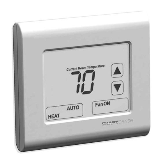
THERMOSTAT OPERATION The SMART 3000 is an easy to use thermostat. Figure 10 Figure 10 shows all LCD elements and the seven buttons (Up/Down/ Make Up Room/Do Not Disturb/On – Off (mode)/Fan Mode/Deg F-C Select. Depending on switch and Installer Menu settings not all LCD segments may be shown. On/Off (Mode) Press the ON/OFF button to turn the thermostat ON or OFF, and if permitted to select heat only or cool only mode. The ON/OFF only Mode is set as the default. -
Page 27: Set Temperature
NOTE: If the thermostat is OFF, touch the thermostat display to turn it ON. Set Temperature Adjust the target temperature with the Up or Down button. The range of temperature adjustment can be limited with the installer setting Heat and Cool limit setting. See page 40. Single fan speed mode (Sw1=Off). See Table 1 DIP Switch Settings, page 11. Press the Fan button to cycle between auto fan and continuous fan mode. Three fan speed mode (Sw1=On). See Table 1 DIP Switch Settings, page 11. Press the Fan button to cycle between low, medium, high and auto fan speeds. Press and hold the Fan button to turn the fan ON continuously. NOTE: Option 36 in the Installer Menu permits you to set the SMART 3000 to automatically reset the indoor fan to Automatic Mode (cycle ON and OFF with heating and cooling) every time the thermostat is turned OFF and then back ON if desired. -
Page 28: Accessory Functions
Ventilation Mode If permitted by DIP Sw7 (Table 1 DIP Switch Settings page 11), the user can run the indoor fan only (Ventilation Mode) when the SMART 3000 is OFF by pressing the Fan button. Press the Fan button to cycle between all available fan speeds. Make Up Room and Do Not Disturb buttons When enabled by DIP Sw8 (Table 1 DIP Switch Settings page 11), press these buttons to activate relevant LCD segments and backlight color on the optional outside door station, and to write data to ModBus for BAS system ACCESSORY FUNCTIONS The SMART 3000 has a number of additional capabilities such as communications with Building Automation Systems (BAS) via its ModBus communications port. The SMART 3000 will automatically control temperature setpoints based on occupancy of the room when a suitable door switch and movement sensor is installed. The SMART 3000 will automatically shut down the air conditioning system if balcony doors or windows are left open when the optional door/ window switches are installed. When you wish to see the room status and have an integrated doorbell from the hallway outside the room, the SMART 3000 can be fitted with the optional hall panel. - Page 29 Complete System Overview The SMART 3000 is the hub of a complete room comfort and energy control system. As shown in Figure 11, the SMART 3000 accepts door, window and Passive Infra-Red (PIR) contact inputs to automatically control temperature setpoints. The wall controller mounted in the hallway outside of the room provides feedback of the guest's needs to housekeeping plus provides a convenient button to activate the SMART 3000 internal door bell. Figure 11 Occupancy Detection The SMART 3000 has sophisticated logic that when connected to your choice of movement sensors, door and window switches will automatically control the setpoint and mode of the SMART 3000.
- Page 30 Figure 12 Using part or all of the functions described below are completely optional. The SMART 3000 will function perfectly as a HVAC controller without the door, window or occupancy detection logic enabled. DO NOT APPLY EXTERNAL VOLTAGES TO THESE INPUTS. Window Contact The window contact input (WC) is used to automatically disable the HVAC system if a window is left open. This is done to prevent energy waste by trying to heat or cool an open room. Window input can be set for a Normally Open (switch open when window is closed) or Normally Closed logic (switch closed when window is closed). When the window is left open for longer than the pre-set time (0 to 300 seconds) the SMART 3000 will automatically turn OFF. The text OFF will flash in the LCD to indicate that the remote window (or door switch) is holding the SMART 3000 in OFF mode. The wall controller will prohibit all changes.
- Page 31 The SMART 3000 will automatically restart once the window is closed. The Installer Menu option 31 Window Input Logic and option 32 Window Input Delay sets the window detection logic in the SMART 3000. Door Switch The Door switch input (DS) is used by the SMART 3000 for two functions. 1. To detect that the door has been opened and then closed to let somebody into or out of the room. 2. To detect if the door has been left open. The door switch input can be set for a Normally Open (switch open when door is closed) or Normally Closed logic (switch closed when door is closed). Installer Menu option 33 Door Input Logic and option 34 Door Input Delay sets the door detection logic in the SMART 3000.
- Page 32 Door Left Open. When the door is left open for longer than the pre-set time (0 to 300 seconds) the SMART 3000 will automatically turn OFF. The text OFF will flash in the display to indicate that the remote door (or window switch) is holding the SMART 3000 in OFF mode. The SMART 3000 will automatically restart once the door is closed. PIR input A PIR (passive infra-red) movement detector can be directly wired to the SMART 3000 PIR input. As movement is detected by the PIR it will send multiple On/Off pulses to the SMART 3000 every time it detects movement. The SMART 3000 using this data along with door switch data will determine the occupancy status of the room and behave accordingly. NOTE: The PIR must be powered separately, typically from a 12V DC supply. Automatic Occupancy Detection Logic Automatic occupancy detection requires the door switch and PIR input to be wired and working.
- Page 33 the SMART 3000 will enter Unoccupied mode where the guest’s temperature and mode will be replaced with installer pre-set values. Should movement be detected within the installer pre-set seek time the SMART 3000 will LOCK into Occupied mode. It will no longer rely on continued movement within the room to remain in Occupied mode. Next time the door is opened and then closed again, the SMART 3000 will again begin its occupancy detection process. NOTE: Even when the SMART 3000 is in Unoccupied mode it will continue to use the PIR input to determine room occupancy. For example - a couple may be staying in the room and one leaves the room leaving the other asleep in bed. As the door closes, the SMART 3000 will seek movement and when none is found it will enter Unoccupied mode. As the sleeper wakes and then moves the SMART 3000 will automatically re-enter Occupied mode even though it may have been some time since the door was closed. Installer option PIR Input Delay sets the PIR mode (On or Off) and the seek time value (1 to 15 minutes).
- Page 34 When the SMART 3000 is in Unoccupied mode, the display will go completely blank except for the words Unoccupied in the top left. If the optional SMART-R- O1H hallway panel is installed its display backlight will go out to let housekeeping know the room is empty. ModBus register 40004 also indicates occupancy status. Doorbell Figure 13 A built-in doorbell feature is included with the SMART 3000 thermostat. This is normally activated by the optional outside door station as described above or via ModBus data link. In circumstances where this is not convenient, the Digital Input (DI) terminals can be reassigned as a doorbell activation switch with the digital input options detailed in the Installer Menu. See page 40. Simply place a momentary volt free switch across DI and Com 0-V terminals to activate the doorbell. Once pressed, the doorbell will chime for about 10 seconds.
- Page 35 Outside Door Station When coupled with the optional SmartSense door station, the guest has the ability to set the room as Do Not Disturb, call for housekeeping or be alerted to visiting guests with a pleasant doorbell chime. Hotel staff are informed about the room status or guest’s needs by text information displayed on the door station LCD or the door station backlight colors. Figure 14 The connection between the SMART 3000 and the hotel door station is cable fitted with RJ12 plugs. When fitting the door station, the SMART 3000 DIP Sw8 must be ON. The outside door station will flash all LCD segments if DIP Sw8 is in the wrong position. Automatic Day Set Temperature The SMART 3000 can optionally reset the user setpoint and replace it with an installer defined setpoint after the SMART 3000 has been OFF for more than six hours. This will typically happen after one guest has checked out and before the next guest checks in. Option 40 in the Installer Menu defines this function. Select OFF or a value between 59 to 86°F (15 to 30°C).
-
Page 36: Modbus Wiring
Modbus Wiring ModBus communications unlock many additional functions within the SMART 3000 thermostat. It also permits all modes, functions and controls to be remotely supervised and adjusted from a central location if needed. ModBus object data can be found on page page 48 of this manual. The SMART 3000 will permit the connection of up to 255 devices on a single ModBus node. Radio frequency noises and other interferences will reduce the real world permitted connections to a maximum of 150 to 200 in most cases. ModBus and other communication protocol rely on the quality of cable and good installation practices to ensure reliable communications. ModBus requires the use of shielded cable with the drain grounded in a single location. When using a common power supply or when using a ModBus master that also powers the SMART 3000, be sure the R (24V AC active), C (24V AC common) Data A and B wires are not crossed. - Page 37 The ModBus data is provided in Addendum 1 at the back of this manual. (page page 48). ModBus relies on a series connection and will normally not tolerate star wiring or T branches. Figure 15 ModBus Master SMART 3000 SMART 3000 SMART 3000 SMART 3000 Figure 16 Correct Wiring...
-
Page 38: Using Remote Temperature Sensors
SMART 3000 SMART 3000 SMART 3000 ModBus Master ModBus SMART 3000 Master SMART 3000 SMART 3000 SMART 3000 SMART 3000 Figure 17 Incorrect Wiring REMOTE TEMPERATURE SENSORS Occasionally the room thermostat cannot be installed in the ideal location to measure the room temperature accurately. In these circumstances the SMART 3000 can use optional remote temperature sensors. These are a two wire device, not polarity dependent and wired into the SMART 3000 sensor inputs terminals SI and Com 0-V. Depending on Installer Menu sensor settings (shown on page 40) remote sensor(s) will either override the SMART 3000 onboard sensor or average with the onboard sensor. Multiple sensors can be used for averaging over larger areas if necessary. Wireless (RF) remote sensors are also available if fixed wiring cannot be installed economically. - Page 39 REMOTE TEMPERATURE SENSOR DIP SWITCH POSITIONS ON = RT1: Single sensor OFF = RT1 and RT2: At least two sensors for averaging When the DIP switch is in ON position, thermistor reflects 10KΩ resistance for single sensor applications. When the DIP switch is in OFF position, a minimum of two sensors are required to average the temperature. SMART-R-02 SMART-R-02 SMART-R-02 SMART-R-02 SMART-R-02 SMART-R-02 Remote Sensor Remote Sensor Remote Sensor Remote Sensor Remote Sensor Remote Sensor Figure 18 Sensor Figure 19 Twin Figure 20 Averaging Sensors...
-
Page 40: Installer Options Menu
Inline Inline Override ON/OFF Switch Switch SMART-R-02 SMART-R-02 SMART-R-02 SMART-R-02 SMART-R-02 SMART-R-02 Remote Sensor Remote Sensor Remote Sensor Remote Sensor Remote Sensor Remote Sensor Figure 21 Four Averaging Sensors Figure 22 Sensor Figure 23 Sensor with Inline Switch with ON/OFF Switch INSTALLER OPTIONS MENU The SMART 3000 has a list of options that can be installer selected. These options tune the thermostat’s performance as well as set energy conservation settings. - Page 41 Navigating Through the Installer Option Settings The bottom right button steps forward through the menu options, the bottom left button steps you backwards. Figure 24 Adjust your options with the up/down buttons. The current menu option is shown between the left and right buttons. The example above shows option 3, select degree F or C display. Exit the menu saving changes by pressing and holding the bottom right button for three seconds or wait three minutes and the SMART 3000 will automatically exit the Installer Menu.
-
Page 42: Installer Options Settings
INSTALLER OPTIONS SETTINGS Table 3 Option Setting Buttons Shown 0: Both mode and fan buttons show (default) 1: Show mode but fan button hidden 2: Show fan but mode button hidden 3: Both mode and fan buttons Hidden Permitted Modes 0: Off / Auto 1: Off / Auto / Heat / Cool 2: Off / Heat /Cool 3: Off / Heat 4 Off / Cool 5: Off / Auto (Display current heating or cooling mode) Room / Set display 0: Show room and set temperature (default) 1: Show set temperature only Native Display Format 0: C (default) 1: F C/F Button Shown On LCD 0: Off (default) 1: On High Temperature Set 41 to 86°F/ 5 to 30°C Limit... - Page 43 Option Setting Low Temperature Set 41 to 86°F/ 5 to 30°C Limit Deadband 0 to 10.0°F degrees/0 to 5.0°C degrees in 0.1°F degree/0.1°C degree steps Data format: Deadband * 10 Fan Purge Period 0: OFF 1: Fan purge - 1 min 2: Fan purge - 3 min 3: Fan purge - 5 min 4: Fan purge - 10 min 5: Heat only fan purge - 1 min...
- Page 44 Option Setting 0 to 10V Fan Interval (PI) 10 to 300 seconds in 10 seconds steps (60 seconds default) 0 to 10V Fan Direction 0: 0 to 10V – slow to fast 1: 10 to 0V – slow to fast 0 to 10V Fan Minimum 0 to 10V Value (minimum fan Data format: 0 to 10V Fan minimum value * 10...
- Page 45 Option Setting Cool Span 1.0 to 6.0°F degrees/0.5 to 3.0°C degrees in 1°F degrees/0.5°C degrees steps Data format: Fan span * 10 0 to 10V Cool Interval (PI) 10 to 300 seconds 10 seconds steps (60 seconds default) 0 to 10V Cool Direction 0: 10V is 100% open (forward acting) 1: 0V is 100% open (reverse acting) 0 to 10V Cool Minimum 0 to 10V Voltage...
- Page 46 Option Setting Unoccupied Fan Mode Fan 3 Speed mode 1: Low (Auto) (default) 2: Med (Auto) 3: High (Auto) 4: Low (ON) 5: Med (ON) 6: High (ON) Backlight 0: On with button press Only 1: Always On high 2: Low when standby / high when active (Default) TT Sensor (SI & Com) 0: Remote – Use this sensor in place of the fitted sensor. 1: Average – Use both remote and fitted sensor and control to the average temperature of both sensors. 2: Data – Sensor value used for ModBus only. 3: Duct – Used for 2 pipe mode. Temperature Calibration +/- 10 degrees (F or C) Adjust to show correct room temp.
- Page 47 Option Setting Digital Input Logic 0: Normally Open 1: Normally Closed Window Input Logic 0: Normally Open 1: Normally Closed Window Input Delay 0 to 300 seconds in 30 second steps (30 seconds default) Door Input Logic 0: Off (default) 1: Normally Open 2: Normally Closed Door Input Delay 0 - 300 seconds in 30 second steps (30 seconds default) PIR Input Delay 0: Off (default)
-
Page 48: Modbus Data Addendum 1
Option Setting Belimo Mode 0: Off 1: On ModBus Address 1 to 255 Baud Rate 1: 4800bps 2: 9600bps 3:19200bps Default Start Temperature 0=OFF (default) 59 to 86°F /15 to 35°C Version 3.3+ Factory Reset 0: No 1: Yes (Exit to initiate) MODbUS DATA ADDENDUM 1 The SMART 3000 has integrated ModBus RTU communications. Using a ModBus master controller, many of the SMART 3000 thermostat features can be centrally controlled and monitored. ModBus is a protocol that is popular because it is robust and simple to implement. Correct wiring practices are required to achieve maximum reliability. - Page 49 entering the address simply as 12. These ModBus registers are shown as Base 1 (PLC addressing) format. Depending on your ModBus master addressing format you may need to subtract 1 from these values to convert to base (protocol addressing) format. NOTE: The ModBus data layout may seem unorganized in this document, for example 0 to 10V for heat and cool is at register 40040 and 40041 while...
- Page 50 Holding Type Value Comments Register 40001 Read Only Device ID Always Returns 131 Use As A Sentinel Point 40002 Read Only Firmware Divide By 100 (e.g. Version 2.36 = 236) Version 40003 Read Only DIP Switch Binary Count State Sw1 = 1, Sw2 = 2, Sw3 = 4, Sw4 = 8 etc 40004 Read / Write Occupancy 0 = Room is Unoccupied Status 1 = Room is Occupied Note - ModBus can write 0 holding the room unoccupied regardless of the occupancy input. Modbus cannot override the occupancy input and hold the SMART 3000 in occupied mode.
- Page 51 Holding Type Value Comments Register 40007 Read / Write HVAC Status 0 = Air Conditioning Off (1 or 3 Fan Speed) 1 = Low Speed Ventilation ( 1 or 3 Fan Speed) 2 = Med Speed Ventilation (3 Fan Speed Only) 3 = High Speed Ventilation (3 Fan Speed only) 4 = Air Conditioning ON (1 or 3 Fan Speed) 40008 Read / Write Fan Status 3 Fan Speed Mode 0 = Low (Fan Auto) 1 = Med (Fan Auto) 2= High (Fan Auto) 3 = Auto Fan Speed (Fan Auto) 4 = Low (Fan On) 5 = Med (Fan On) 6 = High (Fan On) 7 = Auto Fan Speed (Fan On) 1 Fan Speed Mode 0 = Fan Auto 4 = Fan On 40009 Read / Write User Setpoint Deg F = 1°F degree Steps Deg C = 0.5°C degree Steps...
- Page 52 Holding Type Value Comments Register 40010 Read / Write Contact 0 = Off Reception 1 = Show Contact Reception on LCD Notification SMART 3000 LCD will flash Contact Reception on LCD and sound chime. User may accept alert by touching any button on SMART 3000 40011 Read Only Room Value / 10 (e.g. 21.7C = 217) Temperature 40012 Read / Write Temperature 0 = Show Room and Set Temperature Display 1 = Show Set Temperature Only 40013 Read / Write Native F/C 1 = Degree F format Display...
- Page 53 Holding Type Value Comments Register 40017 Read / Write Relay Span 1 to 10°F degrees in 1°F degree Steps 0.5 to 3.0°C degrees in 0.5°C degrees Steps Value / 10 (e.g. 1.0°C Span = 10) Version 3 code – Inactive. Will return valid ModBus data but function internally disabled 40018 Read / Write Fan Purge 0 = Off Period 1 = Fan Purge - 1 Min 2 = Fan Purge - 3 Min 3 = Fan Purge - 5 Min 4 = Fan Purge - 10 Min 5 = Heat Only Fan Purge - 1 Min 6 = Heat Only Fan Purge - 3 Min 7 = Heat Only Fan Purge - 5 Min 8 = Heat Only Fan Purge - 10 Min 9 = Cool Only Fan Purge - 1 Min 10 = Cool Only Fan Purge - 3 Min 11 = Cool Only Fan Purge - 5 Min 12 = Cool Only Fan Purge - 10 Min 40019 Read / Write 0 to 10V Heat 1 to 6°F in 1°F Steps Span 0.5 to 3°C in 0.5°C Steps...
- Page 54 Holding Type Value Comments Register 40020 Read / Write 0 to 10V Cool 1 to 6°F degrees in 1°F degree Steps Span 0.5 to 3°C degrees in 0.5°C degrees Steps Value / 10 (e.g. Cool Span of 1°C = 10) 40021 Read / Write Auto Off 0 = 0ff Timer 1 to 10 Hours. (0.5 hour steps) Value / 10 (e.g. 3 Hour Auto Off Timer = 30) 40022 Read /Write Unoccupied 0 = Off Heat Setpoint 41 to 86°F in 1°F Steps 5 to 30°C in 0.5°C Steps Value / 10 ( e.g. 17°C Unoccupied Heat = 170) 40023 Read / write Unoccupied 0 = Off Cool Setpoint 41 to 86°F in 1°F Steps...
- Page 55 Holding Type Value Comments Register 40024 Read / Write Unoccupied 3 Fan Speed Mode Fan Mode 1 = Low (Fan Auto) 2 = Med (Fan Auto) 3 = High (Fan Auto) 4 = Low (Fan On) 5 = Med (Fan On) 6 = High (Fan On) 1 Fan Speed Mode 0 = Fan Auto 4 = Fan On 40025 Read / Write Backlight 0 = On With Button Press 1 = Always On (High) 2 = Always On Low - High With Button Press 40026 Read / Write Remote SI 0 = Replace On Board Sensor With Remote and Com 0-V 1 = Average Onboard Sensor With Remote Temperature 2 = ModBus Use Only (e.g. Coil Temp Monitor) Input...
- Page 56 Holding Type Value Comments Register 40028 Read / Write Reset Fan 0 = Leave Fan Mode Unchanged Mode 1 = Reset Fan To Auto At Switch Off 40029 Read / Write Belimo Mode 0 = Standard 0 to 10V Valve Logic 1 = Belimo 6V = Off 3 Way Valve Logic 40030 Read / Write Modbus 1 to 255 Address 40031 Read / Write Baud Rate 1 = 4.8Kbs 2 = 9.6kbs 3 = 19.2Kbs 40032 Read Only Digital Input...
- Page 57 Holding Type Value Comments Register 40037 Read Only High Fan 0 = Off Relay Status 1 = Energized 40038 Read Only Medium Fan 0 = Off Relay Status 1 = Energized 40039 Read Only Low Fan Relay 0 = Off Status 1 = Energized 40040 Read Only 0 to 10V Heat Value / 100 (e.g. 7.3V = 730) Value 40041 Read Only 0 to 10V Cool Value / 100 (e.g. 2.1V = 210) Value 40042...
- Page 58 Holding Type Value Comments Register 40045 Read / Write Buttons 0: Both mode and fan buttons show (default) shown on 1: Show mode but hide fan button display 2: Show fan but hide mode button 3: Hide both mode and fan buttons 40046 Read / Write Permitted 0: Off / Auto Modes 1: Off / Heat / Cool / Auto 2: Off / Heat / Cool 3: Off / Heat 4: Off / Cool 40047 Read / Write Swap F/C 1: F/C button shown display shown 0: F/C Button hidden on display 40048 Read / Write Fan Span for 3 1.0 to 6.0°F degrees/0.5 to 3.0°C degrees in...
- Page 59 Holding Type Value Comments Register 40051 Read / Write 0 to 10 Fan 0 to 10V (Fan value x 10) Minimum Voltage 40052 Read / Write 0 to 10 Heat 10 to 300 seconds in 10 second steps Interval (60 seconds default) 40053 Read / Write 0 to 10 Heat 0: 10V is 100% open (forward acting)
- Page 60 Holding Type Value Comments Register 40059 Read / Write Window input 0-300 seconds in 30 second steps Delay 40060 Read / Write Door input 0: Normally Open logic 1: Normally Closed 40061 Read / Write Door input 0 to 300 seconds in 30 second steps Delay 40062 Read / Write...
-
Page 61: Specifications
Holding Type Value Comments Register 40069 Read Only 0 to 10V Fan 0 to 10V (@*10) Max Value 40070 Read / Write Digital Input 0: Normally Open logic 1: Normally Closed 40071 Read / Write Default Start 0:Off Temperature 59 to 86°F or 15 to 35°C Version 3.3+ SPECIFICATIONS Input Voltage... -
Page 62: Specifications
SPECIFICATIONS Memory Type Non-volatile - Settings Do Not Require Battery Back-up Communications Modbus RTU 4.8K / 9.6K / 19.2 K Stop Bit, 8 Data Bits, 1 Start Bit. No Parity. Plastic ABS / Poly Blend – UV Stabilized and Fire Rated Warranty Five Year Limited Warranty TROUbLESHOOTING Table 5 Symptom Problem Solution Temperature Air from the wall cavity may Plug holes in wall with tape to display seems be leaking into the rear of the prevent leaks. inaccurate. thermostat / sensor enclosure. External heat or cool source such Move lamps, vents or as lamps, televisions or drafts from... - Page 63 Symptom Problem Solution Heat/Cool Remote door/window switch is Close windows/door. Check system does holding SMART 3000 in OFF mode. terminals DS and WC are not turn on continuous with terminal COM. automatically. PIR sensor malfunction Check that terminal PIR is continuous with terminal COM. Replace if needed. Heating or SMART 3000 incorrectly set to HP Set Sw2 = OFF and retest cooling runs in mode. heating and cooling operation. deadband. SMART 3000 keeps reversing valve energized after heating/cooling has stopped to limit decompression noise from AC system. Compressor and reversing valve Check C, R, W and Y for correct wiring crossed in HP mode (Sw2...
- Page 64 Symptom Problem Solution Reversing This is not a fault. The reversing valve remains valve remains energized after the heating/ energized cooling has stopped to limit after heating decompression hiss. Reversing or cooling has valve will de-energize within stopped. two hours of the last call. The user This is not a fault. Check options O and 2 for buttons display settings. Check remote...
- Page 65 Symptom Problem Solution HEAT or COOL This is not a fault. Heating or Anti-cycle delay in progress. This is flashing cooling will start shortly. can be disabled if required for in the LCD. commissioning. Heating or cooling has not started. The Fan runs This is not a fault. The fan purge mode is set. on for some Option 8 value.
-
Page 66: Warranty
FIVE YEAR LIMITED WARRANTY Robertshaw warrants to the original contract installer, or to the original consumer user, that each new Robertshaw thermostat will be free of defects in materials and workmanship under normal use and service for a period of five (5) years from the date of purchase (the “Warranty Period”). If any Product fails within the applicable Warranty Period, Robertshaw shall, at its option, repair or replace the Product or credit the purchase price, provided the Product is returned to Robertshaw’s facility or designated agent with transportation charges prepaid, and the Product, upon examination by Robertshaw, is found not to conform to the Warranty. Cost of Product removal, labor, or reinstallation of new Product are not covered under this Warranty and are not the responsibility of Robertshaw. Warranty on Products, parts, components and/or software sold, but not manufactured by Robertshaw, shall be expressly limited to the warranty terms of the manufacturer of such products, components, parts and/or software. - Page 67 TORT, NEGLIGENCE, STRICT LIABILITY, INDEMNITY, PRODUCT LIABILITY, OR OTHERWISE, AND EVEN IF ROBERTSHAW HAS BEEN ADVISED OF THE POSSIBILITY OF SUCH DAMAGES. REPAIR, REPLACEMENT OR CREDIT OF THE PURCHASE PRICE SHALL CONSTITUTE THE SOLE REMEDIES WITH RESPECT TO DEFECTS IN THE PRODUCTS. THE CONSUMER ASSUMES ALL RISKS AND LIABILITY FOR INCIDENTAL AND CONSEQUENTIAL DAMAGE RESULTING FROM INSTALLATION AND USE OF THE THERMOSTAT. Some states does not allow the exclusion or limitation of incidental or consequential damages, or allow limitations on how long an implied warranty lasts, so the above limitations or exclusions may not apply to you. This Warranty gives you specific legal rights, and you may also have other rights which vary from state to state. Return for Warranty Consideration 1. All Products to be considered for warranty must be returned to Company with shipping charges prepaid. 2. Product returned to Company must be packaged in such a manner that will prevent any further damage to the Product during transit.
- Page 68 Robertshaw®, Uni-Line® and SmartSense are trademarks of Robertshaw, its subsidiaries and/or affiliated companies. All other brands mentioned may be the trademarks of their respective owners. Customer Service Telephone 1.800.304.6563 Customer Service Facsimile 1.800.426.0804 HVACCustomerService@robertshaw.com For Technical Service www.uni-line.com www.robertshaw.com Telephone 1.800.445.8299 ©2015 Robertshaw Facsimile 1.630.260.7294 TechnicalService@robertshaw.com 07/15 – 352-00196-001 RevB...
Need help?
Do you have a question about the SmartSense SMART 3000 and is the answer not in the manual?
Questions and answers