Table of Contents
Advertisement
Available languages
Available languages
Quick Links
Item #993-855
Model #41350
UL Model #52-BVD
USE AND CARE GUIDE
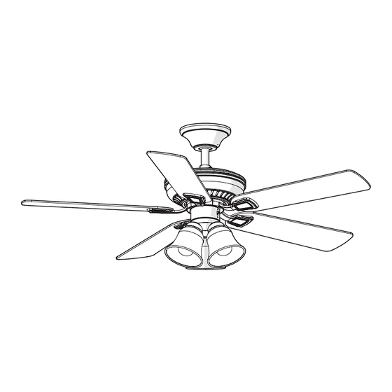
CAMPBELL 52-INCH CEILING FAN
Questions, problems, missing parts? Before returning to the store,
call Hampton Bay Customer Service
8 a.m. - 6 p.m., EST, Monday-Friday
1-855-HD-HAMPTON
HAMPTONBAY.COM
THANK YOU
We appreciate the trust and confidence you have placed in Hampton Bay through the purchase of this ceiling fan. We strive to continually create
quality products designed to enhance your home. Visit us online to see our full line of products available for your home improvement needs.
Thank you for choosing Hampton Bay!
Advertisement
Chapters
Table of Contents

Related Manuals for HAMPTON BAY 41350


Summary of Contents for HAMPTON BAY 41350
- Page 1 THANK YOU We appreciate the trust and confidence you have placed in Hampton Bay through the purchase of this ceiling fan. We strive to continually create quality products designed to enhance your home. Visit us online to see our full line of products available for your home improvement needs.
-
Page 2: Table Of Contents
Table of Contents Table of Contents ..............2 Assembly................7 Safety Information ............... 2 Operation ................15 Warranty ................3 Care and Cleaning ............. 16 Pre-Installation ..............3 Troubleshooting..............16 Installation................6 Safety Information To reduce the risk of electric shock, ensure the electricity has WARNING: To reduce the risk of personal injury, been turned off at the circuit breaker or fuse box before you do not bend the blade brackets (also referred to as... -
Page 3: Warranty
A certain amount of “wobble” is normal and should not be considered a defect. Servicing performed by unauthorized persons shall render the warranty invalid. There is no other express warranty. Hampton Bay hereby disclaims any and all warranties, including but not limited to those of merchantability and fitness for a particular purpose to the extent permitted by law. - Page 4 Pre-Installation (continued) HARDWARE INCLUDED NOTE: Hardware not shown to actual size. Part Description Quantity Part Description Quantity Extra blade bracket screw Hanger pin Extra lock washer Locking pin Plastic wire connector Rubber gasket...
- Page 5 Pre-Installation (continued) PACKAGE CONTENTS Part Description Quantity Part Description Quantity Slide-on mounting bracket Blade (inside canopy) Blade bracket Ball/downrod assembly (with pre-installed screws) Canopy Glass shade Fan-motor assembly Light bulbs (60 Watt maximum) Light kit fitter assembly Remote control (battery included) Receiver IMPORTANT: This product and/or components are governed by one or more of the following U.S.
-
Page 6: Installation
Installation MOUNTING OPTIONS NOTE: You may need a longer downrod to maintain WARNING: To reduce the risk of fire, electric shock proper blade clearance when installing on a steep, sloped or personal injury, mount to an outlet box marked ceiling. The maximum angle allowable is 20° away from “Acceptable for fan support of 35 lbs. - Page 7 Assembly - Standard Ceiling Mount Preparing for standard mounting Routing the wires Remove the canopy ring (M) from the canopy (C) by turning Make sure the slot openings are on top and route the the ring counter-clockwise until it unlocks. wires exiting the top of the fan-motor assembly (D) through the canopy (C) and the canopy ring (L) and then Remove the mounting bracket (A) from the canopy (C) by...
- Page 8 Assembly - Close-To-Ceiling Mount Preparing for mounting Routing the wires Remove canopy ring (M) from the canopy (C) by turning the Remove three of the six screws and lock washers (QQ) (every ring counter-clockwise until it unlocks. other one) securing the motor collar (N) to the top of the fan- motor assembly (D).
-
Page 9: Assembly
Assembly - Hanging the Fan (continued) Hanging the fan WARNING: The hook (XX) is only to balance the fan while making the electrical connections. Failure to hang as shown Close to ceiling mount. Standard mount. may result in the hook (XX) breaking, causing the fan to fall. The hook must pass from the inside to the outside of the canopy. - Page 10 Assembly - Hanging the Fan (continued) Installing the receiver WARNING: To reduce the risk of fire or electric shock, remember to disconnect power. The electrical wiring must meet all local and national electrical code requirements. The electrical source and fan must be 110/120 volt, 60Hz. Do not use this product in conjunction with any variable wall control.
- Page 11 Assembly - Hanging the Fan (continued) Making the electrical connections Outlet box in the ceilin WARNING: Each wire connector supplied with this fan is (MM) designed to accept up to one 12-gauge house wire and two wires from the fan. If you have larger than 12-gauge house wiring or more than one house wire to connect to the fan wiring, consult an electrician for the proper size wire connectors to use.
- Page 12 Assembly - Hanging the Fan (continued) Wrapping the extra wire Mounting the fan-motor assembly (standard mount) WARNING: When using the standard ball/downrod mounting, the NOTE: Follow this step ONLY if you did not cut the extra length off tab in the ring at the bottom of the mounting bracket must rest in from the wires coming from the ceiling fan to the receiver.
- Page 13 Assembly - Hanging the Fan (continued) Mounting the fan-motor assembly (close-to-ceiling mount) WARNING: The locking slots of the canopy are provided only as an aid to mounting. Do not leave the fan assembly unattended until all four canopy screws are engaged and firmly tightened. Carefully unhook the fan from the slide-on mounting bracket (A) and align the locking slots of the canopy (C) with the two screws (SS) in the slide-on mounting bracket (A).
- Page 14 Assembly - Attaching the lights Installing the glass shades Attaching the light kit fitter assembly and bulbs CAUTION: To reduce the risk of electric shock, disconnect WARNING: Allow the glass shades to cool completely before the electrical supply circuit to the fan before installing the removing.
-
Page 15: Operation
Operation OPERATING YOUR FAN Your fan is equipped with a remote control to operate the fan speed and lights of your new ceiling fan. The speed setting for warm or cool weather depends on factors such as the room size, ceiling height, number of fans and so on. The fan is shipped from the factory with the reversing switch positioned to circulate air downward. -
Page 16: Care And Cleaning
Repeat for each blade. Any measurement deviation should be within 1/8 in. Run the fan for ten minutes. If the fan continues to wobble please contact Hampton Bay Customer Service and a balancing kit will be sent to you at no charge. - Page 17 Questions, problems, missing parts? Before returning to the store, call Hampton Bay Customer Service 8 a.m. - 6 p.m., EST, Monday-Friday 1-855-HD-HAMPTON HAMPTONBAY.COM Retain this manual for future use.
- Page 18 GRACIAS POR TU COMPRA. Apreciamos la confianza que has depositado en Hampton Bay al comprar este ventilador de techo. Nos esforzamos para continuamente crear productos de calidad diseñados para tu hogar. Visítanos por Internet para ver nuestra línea completa de productos disponibles para las necesidades de mejoras de tu hogar.
- Page 19 Tabla de contenido Tabla de contenido ............Ensamblaje..............Información de seguridad ..........Funcionamiento............... Garantía ................Mantenimiento y limpieza..........Preinstalación ..............Solución de problemas........... Instalación ............... Información de seguridad Para disminuir el riesgo de descarga eléctrica, asegúrate de ADVERTENCIA: Para reducir el riesgo de lesiones, no cortar la electricidad del cortacircuitos o la caja de fusibles dobles los soportes de las aspas (también llamados antes de comenzar.
-
Page 20: Garantía
Es normal cierta “oscilación” y no debe ser considerado como un defecto. Cualquier servicio técnico conducido por personas no autorizadas anulará la garantía. No hay ninguna otra garantía expresa. Mediante la presente, Hampton Bay se exime de cualquier garantía, incluyendo pero sin limitarse a aquellas de comercialización e idoneidad para un fin particular, de acuerdo a lo contemplado por la ley. - Page 21 Preinstalación (continuación) HERRAJES INCLUIDOS NOTA: No se muestra el tamaño real de los herrajes. Pieza Descripción Cantidad Pieza Descripción Cantidad Tornillo adicional para soporte de Pasador de soporte aspas Pasador de cierre Arandela de seguridad adicional Junta de goma Conector de cables plástico...
- Page 22 Preinstalación (continuación) CONTENIDO DEL PAQUETE Pieza Descripción Cantidad Pieza Descripción Cantidad Soporte deslizante de montaje (dentro Aspa de la cubierta) Soporte de aspa Ensamblaje de tubo bajante/bola (con tornillos preinstalados) Cubierta Pantalla de vidrio Ensamblaje del motor del ventilador Bombillas (máximo de 60 W) Ensamblaje del soporte del kit de luces Control remoto (batería incluida) Receptor...
-
Page 23: Instalación
Instalación OPCIONES DE MONTAJE NOTA: Tal vez necesites un tubo bajante más largo para ADVERTENCIA: Para reducir el riesgo de incendio, descarga eléctrica u otras lesiones, instala sólo en una caja eléctrica mantener la altura mínima adecuada de las aspas, al instalar el ventilador en un techo inclinado. - Page 24 Ensamblaje – Montaje estándar en techo Preparación para montaje estándar Disposición de los cables Retira el aro de la cubierta (L) de la cubierta (C), girando el Asegúrate de que las ranuras estén en la parte superior aro de la cubierta (L) a la derecha hasta destrabarlo. y pasa los cables existentes sobre la parte superior del ensamblaje del motor del ventilador (D) a través de la Retira el soporte de montaje deslizante (A) de la cubierta (C)
- Page 25 Ensamblaje – Montaje "cerca del techo" Preparación para el montaje Disposición de los cables Retira el aro de la cubierta (L) de la cubierta (C), girando el aro Retira tres de los seis tornillos y arandelas de seguridad (QQ) (L) hacia la derecha hasta destrabarlo. (alternados) que sujetan el collarín del motor (N) a la parte superior del ensamblaje del motor del ventilador (D).
-
Page 26: Ensamblaje
Ensamblaje – Cómo colgar el ventilador (continuación) Cómo configurar el código del control Cómo instalar el receptor remoto y el receptor ADVERTENCIA: Para reducir el riesgo de incendio o de descarga NOTA: Las frecuencias del receptor y control remoto han sido eléctrica, recuerda desconectar la electricidad. - Page 27 Ensamblaje – Cómo colgar el ventilador (continuación) Cómo hacer las conexiones eléctricas ADVERTENCIA: Cada conector de cables provisto con este ventilador está diseñado para aceptar cables domésticos de un calibre máximo de 12 y dos cables del ventilador. Si tienes un cableado superior a calibre 12, o más de un cable para conectar al ventilador, consulta a un electricista para conocer el tamaño adecuado de los conectores a usar.
- Page 28 Ensamblaje – Cómo colgar el ventilador (continuación) Cómo montar el ensamblaje del motor Cómo montar el ensamblaje del motor del ventilador (montaje estándar) del ventilador (montaje "cerca del techo") ADVERTENCIA: Cuando uses el ensamblaje del tubo bajante/bola ADVERTENCIA: Las ranuras de cierre de la cubierta sólo sirven de estándar, la pestaña en el aro en la parte inferior del soporte de ayuda durante el montaje.
- Page 29 Ensamblaje - Cómo instalar las lámparas Cómo instalar el ensamblaje del Cómo instalar las pantallas de soporte del kit de luces vidrio y las bombillas PRECAUCIÓN: Para disminuir el riesgo de descarga eléctrica, ADVERTENCIA: Espera que la pantalla de vidrio se enfríe desconecta el circuito de energía del ventilador antes de completamente antes de retirarla.
-
Page 30: Funcionamiento
Funcionamiento CÓMO USAR EL VENTILADOR Tu ventilador está equipado con un control remoto que controla la velocidad y las luces de tu nuevo ventilador de techo. Las configuraciones de velocidad para clima cálido o frío dependen de factores como el tamaño de la habitación, la altura del techo, la cantidad de ventiladores y demás. -
Page 31: Mantenimiento Y Limpieza
Mantenimiento y limpieza ADVERTENCIA: Asegúrate de que la corriente esté apagada antes de limpiar el ventilador. Debido al movimiento natural del ventilador, algunas conexiones pueden aflojarse. Revisa las conexiones de soporte, soportes y accesorios de aspas dos veces al año. Verifica que estén seguros. No es necesario desmontar el ventilador del techo. Limpia tu ventilador con frecuencia, para que luzca como nuevo con el paso de los años. - Page 32 ¿Preguntas, problemas o piezas faltantes? Antes de regresar a la tienda, llama al Servicio al cliente de Hampton Bay de lunes a viernes, entre 8 a.m. y 6 p.m., (hora estándar del Este) 1-877-527-0313 HAMPTONBAY.COM Conserva este manual para consultarlo en el futuro.
Need help?
Do you have a question about the 41350 and is the answer not in the manual?
Questions and answers