Keba KeContact P20 Installation Manual
Hide thumbs
Also See for KeContact P20:
- User manual (200 pages) ,
- Manual (128 pages) ,
- Installation manual (60 pages)
Table of Contents
Advertisement
Quick Links
Advertisement
Table of Contents

Related Manuals for Keba KeContact P20


Summary of Contents for Keba KeContact P20
- Page 1 KeContact P20 Installation manual (for the specialist)
- Page 2 All rights reserved. All intellectual property, including trademarks and copyrights are the property of their respective owners. Any unauthorized use thereof is strictly prohibited. Document: Version 1.41 / Article no.: 90064 KEBA AG, Postfach 111, Gewerbepark Urfahr, A-4041 Linz...
- Page 3 KeContact P20 Contents KeContact P20 bears the CE mark. The corresponding Declarations of Conformity are located at KEBA AG. This product meets the requirements of the ROHS Directive (2011/65/EU). The corresponding Declaration of Conformity is located at KEBA AG. Disposal information...
-
Page 4: Table Of Contents
KeContact P20 Contents Contents Important information........................5 Safety instructions......................... 5 Intended use.......................... 7 About this manual ......................... 7 Product description ....................... 8 Overview ............................9 Variant overview........................9 Optional equipment ......................10 2.2.1 RFID sensor......................10 2.2.2 Key switch......................10 2.2.3... -
Page 5: Important Information
1.1 Safety instructions WARNING! Not observing the safety instructions can result in risk of death, injuries and dam- age to the device! KEBA AG assumes no liability for claims resulting from this! Electrical hazard! The installation, commissioning and maintenance of the charging station may... - Page 6 KeContact P20 Important information WARNING! Pull the charging cable only at the plug and not at the cable out of the connec- tor. Ensure that the charging cable is not mechanically damaged (bent, pinched or run over) and the connection area does not come into contact with heat sources, dirt or water.
-
Page 7: Intended Use
Important information 1.2 Intended use KeContact P20 is a "charging station" for the indoor and outdoor area at which electrically operated vehicles can be charged (e.g. electric automobiles). The charging station is designed for installation on a wall or in a floor-mounted column. -
Page 8: Product Description
KeContact P20 Important information 1.4 Product description Example KC-P20-ES240030-000-xxxx Type plate Product family Product type Type / Version see top of the device Design versions Basic versions Cable / Socket Electronics Electrics Options Optional Customer code Buttons Authentication 2-digit Left Right Installation manual, Version: 1.41 / Article no.: 90064... -
Page 9: Overview
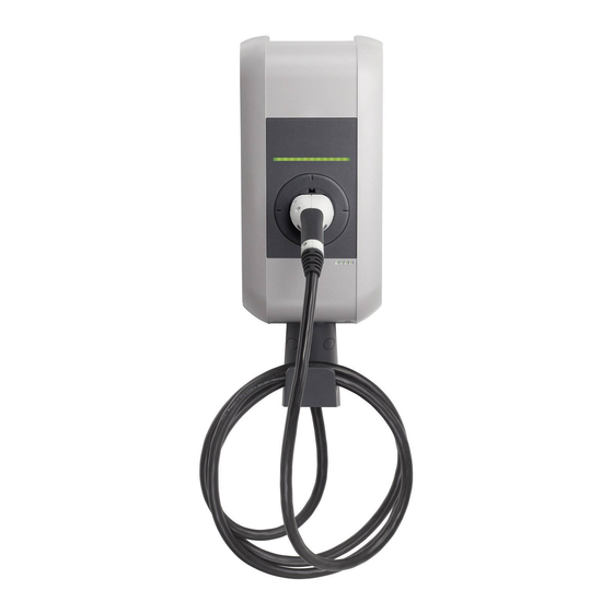
KeContact P20 Overview 2 Overview 2.1 Variant overview Base model with socket (Type 2) Status LED [A]… Standard socket (variants possible) [B]… Housing cover [C]… Charging station (application example) Base model with charging cable (Type 2) Status LED [A]… Parking bay for charging connector [B]…... -
Page 10: Optional Equipment
KeContact P20 Overview Base model with charging cable (Type 1) Status LED [A]… Parking bay for charging connector [B]… Housing cover [C]… Hanger for charging cable [D]… Charging station (application example) 2.2 Optional equipment 2.2.1 RFID sensor RFID sensor The RFID sensor [R] is used for touchless au- thorization of a user with MIFARE cards or tags according to ISO14443. -
Page 11: Additional Optional Equipment
KeContact P20 Overview 2.2.3 Additional optional equipment Network capability Switch contact (for control of external additional equipment e.g. fan) Enable input for e.g. ripple control receivers, time switches,… This permits a scheduled (time-controlled) charging of the vehicle to be realized. -
Page 12: Installation Guidelines
KeContact P20 Installation guidelines 3 Installation guidelines 3.1 General criteria for the site selection The charging station was constructed for the indoor and outdoor area. Accordingly, it is nec- essary to ensure the installation conditions and the protection of the device at the installation site. -
Page 13: Specifications For The Electrical Connection
KeContact P20 Installation guidelines 3.2 Specifications for the electrical connection General The charging station is set to 10 amps in the delivery state. Set the maximum EVSE current capacity by setting the DIP-switches in coordination with your installed line circuit breaker (see chapter “DIP-switch settings”). -
Page 14: Space Requirements
Differing requirements for the fullfillment of „Z.E.-Ready®“ (Renault) 13A charging cables must not be used For 3-phase connection of the KeContact P20, a RCD circuit breaker Type B must be used. Renault recommends the selection of the line circuit breaker according to the follow-... -
Page 15: Installation
KeContact P20 Installation 4 Installation Scope of supply Charging station 1 piece Cable hanger (for versions with charging cable) 1 piece Installation manual (for the specialist) 1 piece User manual (for the end customer) 1 piece Drilling template 1 piece... - Page 16 KeContact P20 Installation Installation requirements Before beginning the installation, the installation guidelines must be observed. Contact person on-site (for access to the mains disconnector in the electrical distribution panel board). The electrical connection (mains supply line) must be prepared.
-
Page 17: Preparing The Housing
KeContact P20 Installation 4.1 Preparing the housing 4.1.1 Removing the housing cover Cover screws ► Unscrew the two cover screws [S] on the bottom side of the housing cover. Cover screws Removing the housing cover ► (1) Pull the housing cover out slightly. -
Page 18: Removing/Mounting The Connector Panel Cover
KeContact P20 Installation 4.1.2 Removing/mounting the connector panel cover Removing the connector panel cover ► Unscrew the four screws with which the connector panel cover is mounted and remove the connector panel cover. Removing the connector panel cover Information for reassembly Mounting the connector panel cover ►... -
Page 19: Preparing The Cable Insertion
KeContact P20 Installation 4.2 Preparing the cable insertion There are two possibilities available for the cable insertion: Cable insertion from above (surface cable routing) Cable insertion from behind (flush-type cable routing) Preparations ► Remove the connector panel cover (see Chapter "Removing/mounting the cable panel cover"). -
Page 20: Cable Insertion From Above - Surface Cable Routing
KeContact P20 Installation 4.2.1 Cable insertion from above - surface cable routing Cable insertion openings - top view [A]…Cable gland M32 (mains supply line) [B]…Cable gland M16 (for control line/Ethernet) [C]…Cable gland M16 (for control line/Ethernet) 4.2.2 Cable insertion from behind - flush-type cable routing... -
Page 21: Mounting The Charging Station
Installation materials that deviate from the supplied standard installation set must be made available on site. A proper mounting is absolutely necessary and lies outside of the scope of responsi- bility of KEBA AG. Please also observe the following manufacturer instructions: Instructions for placing anchors and bolts. Source: Fischer Installation manual, Version: 1.41 / Article no.: 90064... - Page 22 KeContact P20 Installation Marking the holes ► Mark the four holes [1] to [4] using the supplied drilling template and a spirit level. ► Drill the four mounting holes. Information about the drilling template: The drilling template shows the outer contour of the charging station.
- Page 23 KeContact P20 Installation Mounting the charging station ► Turn the hanger bolts into the anchors until the thread still protrudes approx. 2 cm ('x'). ► Use the shims [A] to compensate for any unevenness and to ensure a water drainage behind the device.
-
Page 24: Electrical Connection
KeContact P20 Installation 4.4 Electrical connection 4.4.1 Connection overview with opened connector panel cover Connection overview - Phase conductor 1 [T1]… Service button Mains supply terminal [1]… - Phase conductor 2 [LED]…Status LED (internal) Mains supply terminal [2]… - Phase conductor 3 [X1]…... -
Page 25: Connecting The Mains Supply Line
KeContact P20 Installation 4.4.2 Connecting the mains supply line Running the mains supply line (surface cable routing) ► Run the mains supply line from ABOVE as shown in the figure. [M]… cable sheathing Running the mains supply line Running the mains supply line (flush-type cable routing) ►... - Page 26 KeContact P20 Installation Connecting the mains supply line ► Shorten the connection wires to the appropriate length; these should be kept as short as possible. The PE conductor must be longer than the remaining conductors! ► Strip approx.12 mm from the connection wires.
- Page 27 KeContact P20 Installation Opening the supply terminal ► Push the screwdriver with moderate force straight into the terminal until the wire connector is completely open. During pushing into the supply terminal, the angle of the screwdriver is changing. ATTENTION ...
-
Page 28: Enable Input [X1]
KeContact P20 Installation 4.4.3 Enable input [X1] The enable input is equipped for the use with a potential-free contact. Using the enable input, it is possible to control the charging station using external components (e.g. external key switches, ripple control receiver of the energy supplier, house control, time switches, combi- nation lock, photovoltaic system etc.). -
Page 29: Switch Contact Output [X2]
KeContact P20 Installation 4.4.4 Switch contact output [X2] The switch contact output is a potential-free relay contact and can be used for activating a fan in the garage. This can be necessary with some vehicles. Please consider car require- ments, building requirements and Electric code for installation requirements. The output is not fail-safe! If a fan is used, the corresponding DIP-switch settings must be selected. -
Page 30: Terminals [X1/X2]
KeContact P20 Installation 4.4.5 Terminals [X1/X2] Terminals The terminals for the enable input [X1] and the switch contact output [X2] are designed as spring-type terminals. Terminal data: - Cross-section (min.-max): 0.08 – 4 mm² - AWG (min.-max): 28 – 12... - Page 31 KeContact P20 Installation Color coding: According to the used wiring standard in the building, the contacts are wired according to TIA-568A/B for 100BaseT: -568A -568B -568A -568B Pair Pair Color Color 1 (Tx+) white/green stripe white/orange stripe green/white stripe orange/white stripe or 2 (Tx−)
- Page 32 KeContact P20 Installation Preparing the connection cable ► Strip the connection cable approximately 6 cm. ► Fold back approx. 1 cm of shielded braiding completely and wrap it with conductive adhesive textile tape. Preparing the connection cable Connecting the cable ►...
-
Page 33: Dip-Switch Settings
KeContact P20 Installation 4.5 DIP-switch settings DIP-switches The DIP-switches are used for the addressing and configuring the charging station and are located under the connector panel cover. [DSW1]…configuration (upper DIP-switch) [DSW2]…addressing (lower DIP-switch) DIP-switches DIP-switch example The figure shows for a better explanation, the position of the DIP-switches for the ON and OFF state. - Page 34 KeContact P20 Installation PHASES / ONLY FOR LOAD MANAGEMENT MODE DSW1.3 to DSW1.5 Function DIP-switch Figure only 1 phase Supply (phases) D1.3 OFF= all Phases Phase assignment (*) D1.4 D1.5 Figure Phase L1 at terminal 1 connected Phase L2 at terminal 1...
- Page 35 KeContact P20 Installation SETTING THE AMPERAGE (DSW1) (*1) Current Figure D1.6 D1.7 D1.8 (*1) Preadjusted maximum current value for the EV charger (control pilot duty cycle). STANDARD MODE + DHCP (NO ADDRESSING) DSW2.1 to DSW2.4=OFF / DSW2.6=OFF The charging procedure in STANDARD mode is carried out automatically by the charging station without higher-ranking control system.
- Page 36 KeContact P20 Installation STANDARD MODE + ADDRESSING DSW2.6=ON The charging procedure in STANDARD mode is carried out automatically by the charging station without higher-ranking control system. The charging station has the static IP address: Example: address 17 [192.168.25.xx] Set the desired IP address with the DIP- switches DSW2.1 to DSW2.4 (see “Address-...
-
Page 37: Commissioning
KeContact P20 Installation COMMISSIONING MODE (DSW2.8) Function DIP-switch Figure Commissioning mode D2.8 ON=yes activate 4.6 Commissioning General commissioning process 1. Remove all residual installation and connection materials from the connection area. 2. Before commissioning, check all screw and terminal connections for firm seating! 3. -
Page 38: Commissioning Mode/Self Test
KeContact P20 Installation 4.6.1 Commissioning mode/self test General The charging station can be placed into a commissioning mode for supporting the initial sys- tem test. During this, a self test of the device is performed (interlocking, contactor activation, current measurement, etc.) and the result is displayed. -
Page 39: Safety Checks
KeContact P20 Installation 4.6.2 Safety checks Before the initial use, check the effectiveness of the safety measure(s) of the system accord- ing to the nationally applicable regulations (e.g.:ÖVE/ÖNORM E8001-6-61, DIN VDE 0100- 600:2008-06 "Checks,...")! Electrical systems or devices must be checked by the installer of the system or device before their initial operation. -
Page 40: Mounting The Housing Cover
KeContact P20 Installation 4.6.3 Mounting the housing cover Fitting the housing cover ► Fit the housing cover at the top and push the cover downwards slightly. Make sure that the housing cover is seated correctly at the top in the housing guides. -
Page 41: Further Technical Instructions
KeContact P20 Further technical instructions 5 Further technical instructions 5.1 Programming RFID cards (optional) Programming the RFID master card The authorization by an RFID master card is necessary for the programming. The programming mode can be activated and deactivated using the RFID master card. -
Page 42: Configure The Communication With The Ev Plc->Ethernet (Optional)
KeContact P20 Further technical instructions 5.2 Configure the communication with the EV PLC->Ethernet (optional) To allow the access of the vehicle to the home network or internet, the power line communi- cation between vehicle and charging station must be configured on both sides with the same password (NMK „Network Membership Key“). -
Page 43: Dimensions
KeContact P20 Further technical instructions 5.4 Dimensions Version with standard socket (Type 2) Dimensions in millimeters Installation manual, Version: 1.41 / Article no.: 90064 © KEBA 2012-2013... -
Page 44: Technical Data
KeContact P20 Further technical instructions 5.5 Technical data Electrical data Cable feed: Surface cable routing or flush-type cable routing Mains connection cross-section: Minimum cross-section (depending on the cable and the line length): - 5 x 2.5 mm² (16A nominal current) - 5 x 6.0 mm²... - Page 45 KeContact P20 Further technical instructions Connectors Enable input [X1]: Enable input for external authorization: Connection line: - Cross-section (min.-max): 0.08 – 4 mm² - AWG (min.-max): 28 – 12 Potential-free switch contact output [X2]: Safety extra-low voltage <50V 50/60Hz External current limiting to 0.5A required Connection line: - Cross-section (min.-max):...
-
Page 46: Standards And Regulations
KeContact P20 Further technical instructions 5.6 Standards and regulations EC regulations 2004/108/EC Electromagnetic Compatibility Directive 2006/95/EC Low-Voltage Directive Check of the conformity with the low-voltage directives / electromagnetic compatibility directive EN 61851-1 Conductive charging system for electrical vehicles EN 61851-22 Conductive charging system for electrical vehicles –... -
Page 47: Index
KeContact P20 INDEX 6 INDEX About this manual ..........7 Mounting the charging station......21 Additional optional equipment ......11 Mounting the housing cover......... 40 Cable insertion from above - surface cable routing Optional equipment ..........10 ................. 20 Overview ..............9 Cable insertion from behind - flush-type cable routing ..............
Need help?
Do you have a question about the KeContact P20 and is the answer not in the manual?
Questions and answers