Table of Contents
Advertisement
GENUINE PARKING SENSORS (Rear)
INSTALLATION INSTRUCTIONS
Thank you for purchasing a genuine Mazda accessory.
Before removal and installation, be sure to thoroughly read these instructions.
Please read the contents of this booklet in order to properly install and use the parking sensors
(Rear). Your safety depends on it.
Keep these instructions with your vehicle records for future reference.
There are several
installing or removing the parking sensors (Rear). Always read and follow them in order to prevent
injuries, accidents, and possible damage to the vehicle.
Indicates a situation in which serious injury or death could result if the warning
WARNING:
is ignored.
Indicates a situation in which bodily injury or damage to the vehicle could result if the
CAUTION:
caution is ignored.
For areas indicating the tightening torque in this instruction manual, tighten to the specified torque using
a torque wrench.
Do not modify the parking sensors (Rear).
Do not install the parking sensors (Rear) remove in any way other than described in the following
instructions.
If in any doubt, please ask your Mazda dealer to install the accessory in order to prevent errors in
installation.
If you have any questions about the use of the accessory, ask your Mazda dealer for proper advice
before using it.
Mazda and its suppliers are not responsible for injuries, accidents, and damage to persons and property
that arise from the failure of the dealer or installer to follow these instructions.
To ensure safety and reliability of the work, installation, removal and disposal work must be carried out
by an Authorized Mazda Dealership.
Be careful not to lose removed parts, and be sure that they are kept free from scratches, grease or
other dirt.
PART NAME:
VEHICLE:
PART NUMBER:
NOTE
To the dealer
Please turn over these instructions to the customer after installation.
To the customer
Keep these instructions after installation. The instructions may be necessary
for installing other optional parts or removal of this accessory.
Should the vehicle or this accessory be resold, always leave these instructions
with vehicle for the next owner.
WARNING
WARNING and
CAUTION sections in this booklet concerning safety when
Parking Sensors (Rear)
MAZDA CX-5
KB7W V7 290A (Parking Sensors, Main Kit)
C860 V7 281A (Parking Sensors, Sensor Kit)
KD33 V7 282
(Optional ON-OFF switch)
1
06DE4313B
Advertisement
Table of Contents

Related Manuals for Mazda C860 V7 281A


Summary of Contents for Mazda C860 V7 281A
-
Page 1: Installation Instructions
Do not install the parking sensors (Rear) remove in any way other than described in the following instructions. If in any doubt, please ask your Mazda dealer to install the accessory in order to prevent errors in installation. -
Page 2: Installation View
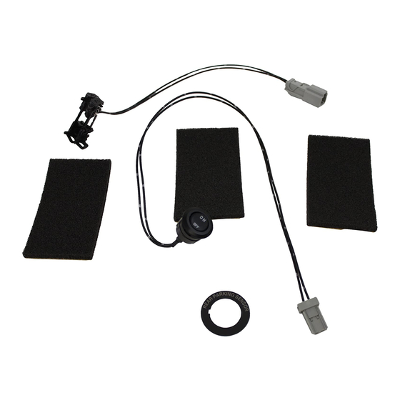
1. INSTALLATION VIEW Control unit Electro tap Buzzer Main harness Grommet Ground wire Rear sensor harness Rear sensor Rear sensor Back sensor 【Optional ON-OFF switch installed】 Back-up sensor ON-OFF switch (Label) Optional ON-OFF switch Trunk side trim (LH) - Page 3 2. PARTS Note Verify that the kit includes all the following parts and that the parts are not dirty, scratched, or damaged. KB7W V7 290 (Parking Sensors, Main kit) Part Part name Qty. Part Part name Qty. Part Part name Qty.
-
Page 4: Before Installation
3. BEFORE INSTALLATION REQUIRED TOOLS ☆Screwdriver (Flathead) ☆Screwdriver (Phillips) ☆Socket wrench ☆Box-end wrench/Combination wrench ☆Torque wrench ☆Nipper ☆Hole saw (20mm) ☆Drill (1.5mm,3mm) ☆Pliers ☆Remover tool ☆Punch ☆Pincers ☆Flathead screwdriver wrapped with protective tape ☆Fastener remover wrapped with protective tape ☆Flat, round file ☆Round file ☆Deburring Tool ☆Masking tape... - Page 5 ■ Branch connection procedure using electro tap 1. Insert the harness and vehicle wiring harness into Vehicle wiring harness the electro tap. 2. Fold the electro tap as shown in the figure and lock Electro tap Vehicle wiring harness CAUTION Lock ...
- Page 6 ■ Securing harness 1. When the wiring harness is secured using a mount Harness base, passing a tie wrap through the mount base and temporarily tightening the wiring harness as shown in the figure will make the operation easier. Tie wrap Mount base ■...
-
Page 7: Connection Diagram
Figure shows connector viewed from harness side. 4.CONNECTION DIAGRAM Wire color indicated in figure is wiring harness color for parking sensor kit. - Page 8 5. VEHICLE PART REMOVAL CAUTION Be careful not to damage or lose any parts removed from the vehicle since they will be reused. Negative battery cable disconnection Negative battery cable 1. Set the selector lever to P range. (AT vehicles only) WARNING ...
- Page 9 Trunk board removal 1. Remove the center trunk board. Center trunk board Note End of center trunk board Move the center trunk board in the direction of the arrows shown in the figure, and remove the ends of the center trunk board from the gap Rear seat back between the trunk side trim and the rear seat back.
- Page 10 Bass-box removal With spare tire Bass box 1. Remove the bolt. Bolt : 4.0—8.0 N·m {41—81 kgf·cm, 36—70 in·lbf} Without spare tire Bass box Bolt : 4.0—8.0 N·m {41—81 kgf·cm, 36—70 in·lbf} 2. Disconnect the connector. With spare tire Short cord 3.
- Page 11 Sub-trunk removal [With spare tire] 1. Remove sub-trunks No.1 and No.2 in the direction of the arrows shown in the figure. Sub-trunk No.1 Sub-trunk No.2 [Without spare tire] With Bose® Without Bose® 2. Remove the sub-trunk in the direction of the arrow shown in the figure.
- Page 12 3. Move the trunk end trim in the order of arrows (1) and Trunk end trim (2) shown in the figure, remove it while detaching the Trunk end trim clips, pins, and the guides. : Guide : Clip : Pin Rear scuff plate removal B-pillar lower trim Rear scuff plate...
- Page 13 3. Hold the shaded areas shown in the figure, move the rear scuff plate in the direction of arrow (1), detach the clip from the inner panel, and pull out the pin. 4. Hold the shaded areas shown in the figure, move the rear scuff plate in the direction of arrow (3), and remove it while detaching tab B of the rear scuff plate from the trunk side trim.
- Page 14 Trunk side trim removal 1. Insert a tape-wrapped flathead screwdriver into the position shown in the figure, move it in the direction Remote handle lever Cover of arrow (1), and while detaching the hooks of the remote handle lever, open the cover in the direction of arrow (2).
- Page 15 5. Remove the bolts. Cargo net hook 6. Remove the cargo net hooks. Bolt Trunk side trim Cargo net hook Bolt Bolt : 9—12 N·m {92—122 kgf·m, 80—106 ft·lbf} 7. Partially peel back the weatherstrips. Weatherstrip Weatherstrip 8. Remove the rear seat cushion. 9.
- Page 16 11. Move the trunk side trim in the order of arrows (1), Left side only (2), (3), and (4) shown in the figure, and remove the clips and hooks. Trunk side trim : Clip : Hook 12. Move the trunk side trim in the order of arrows (1), Right side only Trunk side trim (2), (3), and (4) shown in the figure, and remove...
- Page 17 14. Set the remote handle lever aside. Remote handle lever 15. Move the position of the rear seat back in the Rear seat back direction of arrows (1) and (2) shown in the figure, while adjusting it at a position where the trunk side trim can be removed, move the trunk side trim in the direction of arrow (3) shown in the figure, and remove it in the direction of arrow (4).
- Page 18 Rear combination light removal Rear combination light Note Service hole cover Fogging or condensation on the inside of the rear combination lights may occur due to a natural phenomenon occurring as a result of a temperature difference between the interior and exterior of the combination lights.
- Page 19 5. To prevent scratches or damage, affix protective tape to the position shown in the figure. Protective tape Rear combination light 6. Pull the rear combination light in the direction of Rear combination light arrow (1) shown in the figure and pull out the rear combination light from the body.
- Page 20 9. Turn the grommet counterclockwise and remove it in the direction of arrow (1) shown in the figure. Rear combination light CAUTION When removing the rear combination light from the body, the rear combination light may fall off Grommet and be damaged.
- Page 21 Rear splash shield removal 1. Remove the fastener. Fastener Rear over fender 2. Remove the fastener. Rear over fender Fastener 3. Pull the rear over fender in the direction of the arrow Rear over fender shown in the figure and disengage the clips shown in the figure.
- Page 22 4. Remove the fasteners. 5. Remove the screws. Screw Fastener Fastener Rear splash shield Vehicle front Screw 6. Detach the tabs from the rear bumper and remove the rear splash shield. Rear splash shield...
-
Page 23: Rear Bumper Removal
Rear bumper removal Affix the protective tape to the position shown in the figure to prevent scratches and damage. Protective tape 2. Remove the cap. 3. Remove the screws A and B. Screw A Screw A Screw B Screw B Screw B : 6.9—9.8 N·m {71—99 kgf·cm, 62—86 in·lbf} 4. - Page 24 5. Remove the fasteners. With rear under cover 6. Press the tab of rear under cover and remove it. Rear under cover Fastener 7. Remove the fasteners. Rear bumper Fastener 8. Detach the rear bumper from the rear bumper slider while holding the rear end of the rear bumper, moving it in the direction of the arrows shown in the figure, Hook...
- Page 25 CAUTION Rear fender panel After removing rear bumper, it may hit the rear over fender and cause a damage and/or injury. Perform the following procedure to prevent the rear over fender from being damaged. Protective tape ― Fix the rear over fender and rear fender panel with protective tape.
- Page 26 6. PAINT SENSOR 1. Masking not required. 2. Coat the sensor surface with the body color paint. SURFACE TREA TMENTT a: Paint same as body color CAUTION b: Masking not required Paint characteristics vary according to paint type. Check manufacturer specifications before painting.
-
Page 27: Preparation For Installation
7. PREPARATION FOR INSTALLATION ■ Cutting the cushioning tape 7. Cut the cushioning tape into thirds as shown in the Cushioning tape left figure. ■ Sensor installation Note Installation view Rear bumper surface 20mm 1. Tap the punch into the center of the scribed cross-hair lines for sensor installation on the back side of the bumper. - Page 28 2. Wrap the drill bit with duct tape as shown in the figure. Duct tape 3. Set the drill rotation to low speed. 10mm Drill 3mm CAUTION Always use a drill with a rotation speed adjustment, otherwise the rear bumper may Over-drilling prevention deform.
- Page 29 7. Remove the bezel from the sensor and install it to the surface of the rear bumper with the bezel dot mark on the top. Rear bumper surface Dot mark 8. First install the spacer, then sensor with rubber to the back side of the rear bumper. CAUTION ...
-
Page 30: Control Unit Installation
■ Control unit installation 1. Affix double-sided adhesive tape to the control unit. CAUTION Double-sided Always remove dirt or oil because the adhesive strength of adhesive the double-sided adhesive tape weakens. Control unit 2. Peel off the double-sided adhesive tape backing and adhere the control unit to the body panel of the lower part inside of the trunk side trim (driver’s side). - Page 31 8.INSTALLATION OF THE HARNESS [ Main harness ] (1) Connect the main harness to the control unit. (2) Connect the main harness to the buzzer. Control unit (3) Install the main harness. (4) Tie redundant part using ▲ tie wrap. To ②...
- Page 32 [ Sensor harness (1) ] Vehicle with BSM ※ Install the wiring harness to the cabin interior from the rear bumper side. Center mark (white tape) Sensor harness To ② Connector for back sensor Vehicle front ♦ Mount base (7) Connector for right back sensor Connector for left rear sensor Tie wrap (8)
- Page 33 [ Sensor harness (1) ] Vehicle without BSM ※ Install the wiring harness to the cabin interior from the rear bumper side. Center mark (white tape) Sensor harness To ② Connector for back sensor Vehicle front ♦ Mount base (8) Connector for right back sensor Connector for left rear sensor Tie wrap (8)
- Page 34 [ Sensor harness (2) ] ※ Install the wiring harness to the cabin interior from the rear bumper side. (1) Insert sensor harness terminals to female contact housing. (2) Connect the sensor harness connector to the control unit. Female contact housing Sensor harness Control unit (Blue)
- Page 35 [ Sensor harness (3) ] (3) Secure the main harness and sensor harness to the vehicle wiring harness using ▲ tie wraps. (1) Install the main harness and sensor harness Vehicle wiring harness Control unit To ⑤ (2) Tie redundant part using ▲...
- Page 36 9.INSTALLATION OF OPTIONAL ON-OFF SWITCH FOR USE WHEN TOWING Note This procedure is not necessary if the [optional on-off switch for use when towing] is not installed. Go to 9. CAUTIONS WHEN RE-INSTALLING. ■Optional ON-OFF switch installation 2. Mark the back side of the driver-side trunk side trim Back side of driver-side trunk side trim in the position shown in the figure using a punch.
- Page 37 6. Drill a hole in the center of each Optional ON-OFF switch hole using a hole saw 20mm. Driver-side trunk side trim Drill (1.5mm) Notch hole Optional ON-OFF switch hole Hole saw 20mm Drill (1.5mm) Center of the Optional ON-OFF switch hole 7.
-
Page 38: Harness Installation
■ Harness installation 1. Cut the main harness (Red wire) at the position shown in the figure. 2. Strip the main harness insulation and wrap electrical vinyl tape around the tip of the stripped RBCM main harness for insulation. CAUTION ... - Page 39 10.CAUTIONS WHEN RE-INSTALLING 1. Reinstall parts in the reverse order of the installation procedure in “VEHICLE PARTS REMOVAL”. Connect the main wiring harness to the rear sensor. Connect the optional on-off switch harness to the harness. Back side of driver-side trunk side trim Harness connector Optional ON-OFF switch harness connector Vehicle front...
-
Page 40: Operation Condition
11.OPERATION CONDITION ■ Is available when the ignition is switched ON and shift lever is in the R position. ■ The sensor detects obstructions when the shift lever is in the R position. ・ Alarm (beeper) sound ■ The beeper operates (sounds) as follows while the system is operating. ◇Back sensor ◇...
Need help?
Do you have a question about the C860 V7 281A and is the answer not in the manual?
Questions and answers