Table of Contents
Advertisement
Advertisement
Table of Contents

Related Manuals for thomann The t.mix 16.4


Summary of Contents for thomann The t.mix 16.4
- Page 1 16.4 Mixer user manual...
- Page 2 Musikhaus Thomann Thomann GmbH Hans-Thomann-Straße 1 96138 Burgebrach Germany Telephone: +49 (0) 9546 9223-0 E-mail: info@thomann.de Internet: www.thomann.de 26.06.2018, ID: 433542...
-
Page 3: Table Of Contents
Table of contents Table of contents General information......................4 1.1 Further information......................4 1.2 Notational conventions....................4 1.3 Symbols and signal words................... 4 Safety instructions......................... 6 Features............................8 Installation..........................9 Connections and controls....................10 Operating..........................16 6.1 Main menu........................16 6.2 Parametric equalizer.................... -
Page 4: General Information
Our products are subject to a process of continuous development. Thus, they are subject to change. 1.1 Further information On our website (www.thomann.de) you will find lots of further information and details on the following points: Download This manual is also available as PDF file for you to download. - Page 5 General information Signal word Meaning DANGER! This combination of symbol and signal word indicates an immediate dangerous situation that will result in death or serious injury if it is not avoided. NOTICE! This combination of symbol and signal word indicates a possible dangerous situation that can result in mate- rial and environmental damage if it is not avoided.
-
Page 6: Safety Instructions
Safety instructions Safety instructions Intended use This device is intended to be used for amplification, mixing and playback of signals from musical instruments and microphones. Use the device only as described in this user manual. Any other use or use under other operating conditions is considered to be improper and may result in personal injury or property damage. - Page 7 Safety instructions NOTICE! Operating conditions This device has been designed for indoor use only. To prevent damage, never expose the device to any liquid or moisture. Avoid direct sunlight, heavy dirt, and strong vibrations. NOTICE! Power supply Before connecting the device, ensure that the input voltage (AC outlet) matches the voltage rating of the device and that the AC outlet is pro- tected by a residual current circuit breaker.
-
Page 8: Features
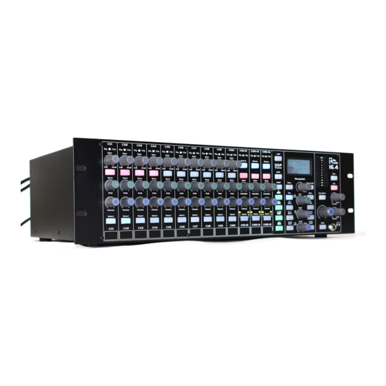
Features Features 10 microphone inputs with separate volume and tone controls, each as XLR and 1/4" phone sockets 16 line inputs with separate volume and tone controls, 10 of which as XLR and 1/4" phone sockets, and 6 as 1/4" phone sockets Line output /stereo, XLR chassis plug) Control room output (stereo, as 1/4"... -
Page 9: Installation
Installation Installation NOTICE! Danger of short circuit Switching on phantom power will damage the device if unbalanced XLR cables are connected. Only turn on phantom power when exclusively balanced XLR cables are connected. Unpack and carefully check that there is no transportation damage before using the unit. -
Page 10: Connections And Controls
Connections and controls Connections and controls Overview Input settings Tone and signal processing settings Output settings Mixer... - Page 11 Connections and controls Input settings 1 [Sig / Clip] The LED lights up green if there is a signal on the corresponding input (signal level > –30 dB). The LED lights up red if the signal level is to high and distortion results from overload (signal level > +15 dB). In this case, reduce the signal level using the [Gain] control.
- Page 12 Connections and controls Tone, signal processing and output settings 8 Display 9 [Parameter] Control for selecting the channel or navigating the menu. Pressing the control opens a menu item or confirms a setting. 10 [EQ Freq / Pan / THR] Depending on the menu item that has just been selected, either sets the centre frequencies of the equalizer, the position in the stereo field or the threshold for the noise gate and compressor.
- Page 13 Connections and controls 16 [Aux1 Level], [Aux2 Level] Selects the bus Aux1 or Aux2 for setting the volume ([EQ Gain / Level / Gain] control), balance ([EQ Freq / Pan / THR] control), compressor and equalizer, and for muting ([Mute] button). 17 [Aux1 Send], [Aux2 Send] Opens the menu for selecting and setting the level of the input channels for the output [AUX Send 1] or [AUX Send 2].
- Page 14 Connections and controls 29 [Phones] Volume control for the headphones output 30 Monitor output for headphones, designed as 1/4" phone socket (stereo) 31 [Main] Selects the bus Main for setting the volume ([EQ Gain / Level / Gain] control), balance ([EQ Freq / Pan / THR] control), and for muting ([Mute] button).
- Page 15 Connections and controls Rear panel 34 [ETHERNET] RJ45 socket for integrating the device into a local network (LAN) or for firmware updates. 35 [CH11]…[CH16] Inputs for signals with line levels, designed as as 1/4" phone sockets (stereo, balanced). If a mono signal is fed in, use the channel marked [LEFT].
-
Page 16: Operating
Operating Operating 6.1 Main menu Important settings are directly accessible in the main menu. Press [Menu]. Use the [Parameter] control to select, to set values, and to navigate the menu. Pressing the control opens a menu item or confirms a setting. The table below provides a overview of the available menus. -
Page 17: Parametric Equalizer
Operating 6.2 Parametric equalizer A parametric equalizer with four frequency bands can be switched on for each input channel and each bus. Press one of the [Select] buttons for an input channel or one of the [FX Level], [Aux1 Level], [Aux2 Level] or [Main] bus selection buttons for a bus. ð... - Page 18 Operating Press [Menu]. Use the [Parameter] control to select the menu item ‘GEQ’ . Press the [Parameter] control. ð The ‘GEQ’ menu will open in the display. Press the [Main], [Aux1 Level], [Aux2 Level] to select the output for which you would like to set the graphic equalizer.
-
Page 19: Compressor
Operating 6.4 Compressor A compressor can be switched on for each input channel and each bus. Press one of the [Select] buttons for an input channel or one of the [FX Level], [Aux1 Level], [Aux2 Level] or [Main] bus selection buttons for a bus. ð... -
Page 20: Noise Gate
Operating 6.5 Noise Gate A noise gate can be switched on for each input channel and the bus FX. Press one of the [Select] buttons for an input channel or the [FX Level] bus selec- tion button. ð The button of the selected input channel or bus lights up blue. Press [GATE]. -
Page 21: Technical Specifications
Technical specifications Technical specifications Input level (Mic/Line) XLR connections (balanced): max. +20 dBu 1/4" phone socket (unbalanced): max. +20 dBu Input impedance Mic: 6.8 kΩ Line: 75 kΩ Stereo: 27 kΩ Total harmonic distortion (THD) < 0.03 %1 kHz Frequency range 20 Hz…20 kHz, 0 dBu ±1.5 dB Signal-to-noise ratio 108 dB... - Page 22 Technical specifications Dimensions (W × H × D) 484 mm × 140 mm (3 HE) × 300 mm Weight 6.98 kg Block diagram Mixer...
-
Page 23: Plug And Connection Assignment
Plug and connection assignment Plug and connection assignment Introduction This chapter will help you select the right cables and plugs to connect your valuable equipment in such a way that a perfect sound experience is ensured. Please note these advices, because especially in ‘Sound & Light’ caution is indicated: Even if a plug fits into the socket, an incorrect connection may result in a destroyed power amp, a short circuit or ‘just’... - Page 24 Plug and connection assignment XLR plug (balanced) Ground, shielding Signal (in phase, +) Signal (out of phase, –) Shielding on plug housing (option) Mixer...
-
Page 25: Protecting The Environment
Protecting the environment Protecting the environment Disposal of the packaging material For the transport and protective packaging, environmentally friendly materials have been chosen that can be supplied to normal recycling. Ensure that plastic bags, packaging, etc. are properly disposed of. Do not just dispose of these materials with your normal household waste, but make sure that they are collected for recycling. - Page 26 Notes Mixer...
- Page 28 Musikhaus Thomann · Hans-Thomann-Straße 1 · 96138 Burgebrach · Germany · www.thomann.de...
Need help?
Do you have a question about the The t.mix 16.4 and is the answer not in the manual?
Questions and answers