Table of Contents
Advertisement
OWNER'S MANUAL
If you do not have prior experience with
a metal detector, we strongly
recommend you:
1) Adjust the Sensitivity to a
low setting in the event of
false signals. Always begin
use at a reduced sensitivity level.
Expect chatter or internal noise at high
sensitivity.
2) Do not use indoors. This detector is for outdoor
use only.
electromagnetic energy, which can interfere with
the detector.
demonstration, turn the sensitivity down and keep
the searchcoil away from appliances such as
computers, televisions and microwave ovens. If
your detector beeps erratically, turn off appliances
and lights.
Also keep the searchcoil away from
objects containing metal, such as
floors and walls.
3) Use a 9-volt ALKALINE battery
only. Do not use Heavy Duty
Batteries.
Many household appliances emit
If conducting an indoor
Also available
with 11"DD coil
(Item# OMEGA-11DD)
Advertisement
Table of Contents

Related Manuals for Teknetics Omega 8500


Summary of Contents for Teknetics Omega 8500
- Page 1 OWNER’S MANUAL If you do not have prior experience with a metal detector, we strongly recommend you: 1) Adjust the Sensitivity to a low setting in the event of false signals. Always begin use at a reduced sensitivity level. Expect chatter or internal noise at high sensitivity.
-
Page 2: Table Of Contents
TABLE OF CONTENTS Terminology ..........3 Assembly . -
Page 3: Terminology
TERMINOLOGY The following terms are used throughout the manual, and are standard terminology among detectorists. Reference to a metal being "eliminated" means the detector will not emit ELIMIN TION a tone, nor light up an indicator, when a specified object passes through the coil’s detection field. -
Page 4: Assembly
ASSEMBLY Adjusting the Armrest The armrest may be moved forward or backward by removing the single screw and nut and then repositioning the 2-piece armrest. Users with shorter arms may find the armrest more comfortable in the forward position. In order to move the armrest backward, the plastic plug must be removed from the aluminum tube. - Page 5 ASSEMBLY continued) Caution: Forcing in MIDDLE STEM with CAM LOCK raised may form a burr on cam lock. If this happens, remove burr with knife to allow insertion. Position S-Rod upright. Rotate the LOCKING COLLAR fully in the counterclockwise direction. Insert your finger inside the tube and make sure the INTERNAL CAM LOCK is flush with the inside of the tube.
-
Page 6: Batteries
BATTERIES The detector requires a single 9-volt ALKALINE battery (battery not included). Do not use ordinary zinc carbon batteries. Do not use “Heavy Duty” batteries. Rechargeable batteries can also be used. If you wish to use rechargeable batteries, we recommend using a Nickel Metal Hydride rechargeable battery. The battery compartment is located on the back side of the housing. -
Page 7: Quick-Start Demo
QUICK-START DEMONSTRATION I. Supplies Needed • Nail • Zinc Penny (dated after 1982) • Nickel • Quarter II. Position the Detector a. Place the detector on a table with the searchcoil hanging over the edge. Or better, have a friend hold the detector, with the searchcoil off the ground. -
Page 8: Quick-Start Demo
QUICK-START DEMONSTRATION continued) VIII. Firmly press and release once. DISC LVL will be activated. Press until the words IRON, FOIL, NICKEL, P-TAB, S-CAP and ZINC all disappear. IX. Wave the Nickel over the searchcoil. a. The nickel will not be detected. Firmly press and release two times. -
Page 9: Basics Of Metal Detecting
THE BASICS OF METAL DETECTING A hobby metal detector is intended for locating buried metal objects. When searching for metals, underground or on the surface, you have the following challenges and objectives: 1. Ignoring signals caused by ground minerals. 2. Ignoring signals caused by metal objects that you do not want to find, like pull-tabs. -
Page 10: Emi
THE BASICS OF METAL DETECTING (continued) The searchcoil produces a magnetic field and then detects changes in that 5. EMI (Electromagnetic Interference) magnetic field caused by the presence of metal objects. This magnetic field is susceptible to the electromagnetic energy produced by other electronic devices. -
Page 11: Operation And Controls
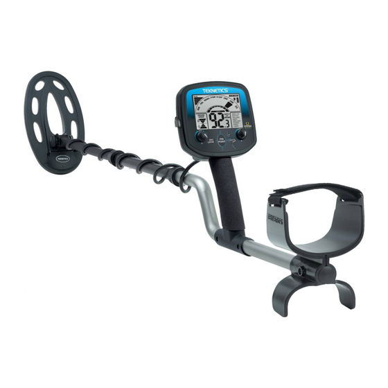
OPERATION and CONTROLS Mineralization Iron Signal Strength Readout Indicator Bargraph Target Overload Target Category Indicator Categories Identifiers ® Mode Battery Backlight Ground Error Number window Identifiers Auto Menu Ground Items Offset ON/OFF/GAIN: Click right to turn ON. DISC/AM/THRESH Click left to enter Turn knob to increase GAIN. -
Page 12: Control Knobs
DISC LVL NOTCH VOLUME DEEP GROUND OPERATION and CONTROLS (continued) TONES FREQ FREQ LIGHT LIGHT CONTROL KNOBS: a. Click right to turn on. Click left to turn off. 1. ON/OFF/G IN: b. Turning the knob clockwise increases the detector’s Gain; the higher the Gain, the deeper targets will be detected, and the more likely the detector will be able to detect very small targets. -
Page 13: Separate Gain And Threshold Controls
OPERATION and CONTROLS (continued) The gain setting factors the amplitude of the signal coming from the coil. The Separate Gain and Threshold controls threshold setting sets the minimum signal strength required to get a response, and audibly, the “hum” level in All Metal Mode. Together, these two settings control the overall sensitivity of the machine. -
Page 14: Pinpoint Retuning
OPERATION and CONTROLS (continued) Retuning in Pinpoint Mode is useful in narrowing down the location of a target. PINPOINT RETUNING To retune the detector, release the button and immediately depress it again. 1. To Narrow the response further, position the center of the searchcoil slightly off the center of the target, while still depressing 2. -
Page 15: Menu Items
MENU ITEMS Discrimination allows you to eliminate metal objects from detection. It is DISC LVL: Discrimination Level adjustable from 0 to 80. A discrimination setting of zero is not the same as All Metal. Discrimination incurs some loss of sensitivity to small and deep objects. As you adjust the discrimination level, a number will appear in the center of the LCD. -
Page 16: Notch Volume
MENU ITEMS (continued) Each target category can have its volume adjusted independently. This NOTCH VOLUME – djustable Volume Offset by Target Category advanced setting affects the Master Volume setting and functions only in DISCRIMINATION Mode. Access: In Disc Mode, press and release until VOLUME menu is activated. -
Page 17: Ground Grab Offset
This number will be added or subtracted from the Ground Grab setting, depending on your entry. In Discrimination Mode, the Omega 8500 has 5 different pre-set tone variations TONES: Variable Tone Selections to choose from. See the table below detailing the settings of the 5 options. -
Page 18: Frequency Shifting
LIGHT menu item is activated. Use the to select desired backlight setting. Use the “0” setting to turn backlight off. The Omega 8500 will save in memory your settings when the detector is turned NONVOL TILE MEMORY off, with the exception of the backlight and ground balance. Backlight default is OFF and Ground Balance is 82.9. -
Page 19: Ground Balancing
GROUND BALANCING WH T IS GROUND B L NCING? Why do I need to Ground Balance? All soils contain minerals. Signals from ground minerals are often tens or hundreds of times as strong as the signal from a buried metal object. -
Page 20: Fe Bar Graph
GROUND BALANCING -Technical Info BAR GRAPH The Fe 4-segment bar graph indicates the amount of ground mineralization, independent of type, expressed as an equivalent volume concentration of magnetite (Fe ). It updates every second. It is sensitive to motion and will give the most accurate readings if you “pump”... -
Page 21: Ground Error
GROUND ERROR continued) * When the detector’s internal Ground Setting is lower than the actual phase of the ground, the bars on the bottom of the graph will be illuminated. The bigger the error is, the more bars will show up. * If the Ground Error exceeds the level of three bars, will appear, indicating the maximum error has been reached, and action must be taken... -
Page 22: Depth And Target Display
DEPTH AND TARGET DISPLAY The Liquid Crystal Display (LCD) shows the PROBABLE identification of the RE DING THE DISPL Y targeted metal, as well as the PROBABLE depth of the target. The detector will register a consistent target identification, upon each sweep of the coil, when a buried target has been located and identified. - Page 23 PRIMARY available only Discrimination Mode. For each target, the Omega 8500 calculates four independent numerical Target-ID’s on each pass of the coil; one primary and three secondary. Each one of the Target-ID’s will correlate to a target category on the LCD. There will be one solid primary category lighting up and up to three additional secondary target categories.
-
Page 24: Common Target Value Table
DEPTH AND TARGET DISPLAY continued) Noise can trigger secondary TIDs without a primary, so it is possible to see secondary Reading the display (cont.) TID categories light up on the display, without a primary solid TID category. Secondary Target-IDs don’t produce any audio report and cannot be discriminated out. -
Page 25: Search Techniques
SEARCH TECHNIQUES (Motion modes) Target Verification After detecting a target, do the following: WRONG 1. Walk around the target in a circle. 2. While circling target, continue sweeping searchcoil across the target. 3. Sweep once every 30° or 40° CORRECT of the circle. -
Page 26: Target Pinpoint
TARGET PINPOINTING (static search) After you have identified a target using a motion mode of detection, press-and-hold to identify the target’s exact location. This technique can yield more information about the target’s shape and size and also find its exact location to facilitate extraction. Pinpoint also changes the readout to indicate target depth in inches. -
Page 27: Code Of Ethics
TRE SURE HUNTER’S CODE OF ETHICS: • lways check Federal, State, County and local laws before searching. • Respect private property and do not enter private property without the owner’s permission. • Take care to refill all holes and leave no damage. •... -
Page 28: Accessories
– Stereo Headphones ® Use with Teknetics metal detectors with true stereo. Utilizes 1/4-inch stereo & 1/8-inch plug. Compatible with all Teknetics models with ® 1/4-inch & 1/8-inch jacks. – HEADT Pinpointer Pinpoints the exact location of buried metal objects. Audio signal indicator and vibrator.
Need help?
Do you have a question about the Omega 8500 and is the answer not in the manual?
Questions and answers