
Related Manuals for York YPC


Summary of Contents for York YPC
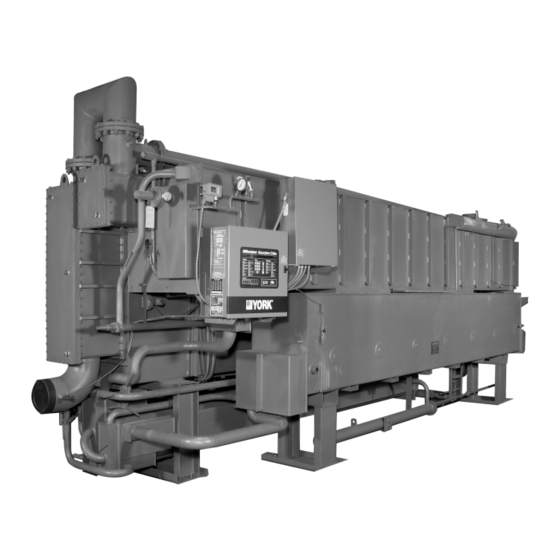
- Page 1 FORM 155.19‑EG3 (1011) Model YPC Two‑Stage Steam‑Fired Absorption Chiller Style D Models YPC‑ST‑14SC through YPC‑ST‑19S 300 through 675 Tons 1050 through 2372 kW...
-
Page 2: Table Of Contents
FORM 155.19-EG3 (1011) Table of Contents FORM 155.19‑EG3 (1011) ..................................... 1 Introduction ........................................... 3 How It Works ........................................4 Ratings ..........................................5 MicroComputer Control Center ................................... 6 Mechanical Specifications ....................................8 Optional Features ........................................11 Application Data ......................................... 12 Dimensions ......................................... 17 Nozzle Arrangement 14SC .................................... -
Page 3: Form 155.19-Eg3 (1011)
Steam Absorption Chiller is the ideal choice for a wide range of applications. YPC Steam Chillers come equipped with the same sophisticated microprocessor controls found throughout Johnson Controls’ line of large tonnage chillers, making the YPC Steam Chiller the smart- est and most efficient absorber on the market today. -
Page 4: How It Works
First-Stage Generator. takes place. YPC’s absorption chilling cycle is continuous; however, for the sake of clarity and simplicity, it is divided This is the heart of the remarkably efficient two-stage into six steps. -
Page 5: Ratings
Two-Stage design delivers superior tions. Computerized performance ratings are available economy at low loads. Table 1 details the YPC machine’s through each Johnson Controls sales office. superior IPLV according to ARI 560-2000. -
Page 6: Microcomputer Control Center
When automatic capacity control is desired, the Micro- As standard equipment on all Millennium YPC Two-Stage Computer Control Center automatically varies the steam Absorption chillers, the Control Center is a major develop-... - Page 7 FORM 155.19-EG3 (1011) WARNING CONDITIONS/INHIBITED UNIT LOADING When in the PROGRAM mode, an operator can use the concentration calculator to determine concentration by The MicroComputer Control Center provides a warning inputting set of conditions. The operator must input any annunciation and, when beneficial to the machine, will two of three parameters (bromide solution temperature, limit heat input to 30% to 60% when operating conditions saturation temperature, and pressure) and the micropanel...
-
Page 8: Mechanical Specifications
DRAIN COOLERS The side of the main shell closer to the generator contains YPC Absorption steam units come equipped with a con- the intermediate pressure section of the machine consist- densate drain cooler, eliminating the need for a separate... - Page 9 20% to 100%. installed isolation valves to permit quick and easy servic- ing of pumps. All YPC units include two solution pumps The YPC chiller design incorporates a float valve that and a refrigerant pump. Pumps are designed to operate...
- Page 10 FACTORY LEAK TEST start after power failure is selected. Each YPC unit is subjected to a series of four rigorous leak tests, culminating in a vacuum leak test measured Operating Controls – Background messages are...
-
Page 11: Optional Features
NESS • Absorber solution concentrations • All liquid levels in the sightglasses Millennium YPC Absorption units are designed for long life with the stand ard tube materials and wall thicknesses in • Exact solution and refrigerant charge amount each heat exchanger. For special applications where dif-... -
Page 12: Application Data
3.3 and 10 fps (1.0 and 3.05 m/s). YPC chillers are de- ANSI/AWWA C-606 couplings (ANSI flanges are optional). signed for constant flow systems. Applications involving... - Page 13 (not in standard supply scope, but available from All YPC chillers ship with a rupture disk(s) de signed to fail Johnson Controls) installed in the tower water piping in the at 12 PSIG (0.83 bar).
- Page 14 ∆PH2 + ∆PPIPING + ∆PVALVE = 15.0 PSIG (1 bar) STEAM General – The YPC unit is nominally rated for dry steam Where: with minimal superheat, and a pressure of 115 PSIG (7.93 bar) (at the steam valve). The inlet steam must not have a ∆PH2 = Pressure drop due to height, H2...
- Page 15 FORM 155.19-EG3 (1011) spray header pump and one refrigerant pump. FIG. 4 – PIPING LAYOUT NOTES: 5. Automatic shutoff valve to be failsafe type. 1. H = 15 in. (381 mm) minimum to prevent condensate backflow. 6. Both the steam supply and condensate drain pipes must be prop- erly sized and pitched to prevent hammering.
- Page 16 FORM 155.19-EG3 (1011) Application Data ‑ continued TABLE 2 – ELECTRICAL DATA SOLU‑ NON‑FUSED SPRAY REFRIG PURGE ELEC CHILLER VOLT. WIRE DUAL TION TOTAL TOTAL VOLTAGE DISCONNECT PUMP PUMP PUMP PANEL MODEL CODE AMPACITY ELEMENT PUMP CURRENT SWITCH FUSE 200/208V-3PH-60Hz 43.7 60A/240V 60/250V...
-
Page 17: Dimensions
FORM 155.19-EG3 (1011) Dimensions Johnson Controls is committed to a policy of continuous product improvement. Dimensions subject to change without notice. Consult factory-submitted drawings. RIGGING WEIGHT CONDEN‑ INSULATION AREAS OPERATING STEAM LENGTH WIDTH (IN.) HEIGHT SATE UNIT TYPE WEIGHT INLET PIPE LBS. -
Page 18: Nozzle Arrangement 14Sc
NO. OF PASSES (IN) (OUT) PASSES ARRANGEMENT ARRANGEMENT NOZZLE SIZES EVAPORATOR ABS./COND. YPC-ST NUMBER OF PASSES 14SC 6” 6” 4” 6” 6” 4” *Number of passes refers to the number of absorber passes only. The condenser is always one pass with nozzle sizes that match the absorber. -
Page 19: Nozzle Arrangement 16Sl And Larger
FORM 155.19-EG3 (1011) Nozzle Arrangement 16SL and Larger STEAM INLET OPPOSITE END LD01008 EVAPORATOR NOZZLE ARRANGEMENTS TOWER WATER NOZZLE ARRANGEMENTS NOZZLE NOZZLE NO. OF PASSES (IN) (OUT) ABSORB. COND. NO. OF ABS. ARRANGEMENT ARRANGE- PASSES MENT NOZZLE SIZES EVAPORATOR ABS./COND. UNIT NUMBER OF PASSES 16SL &... -
Page 20: Guide Specifications
FORM 155.19-EG3 (1011) Guide Specifications GENERAL WATER BOXES Provide YORK Millennium YPC Two-Stage Absorption Water boxes shall be removable to permit tube cleaning Steam-Fired Chiller(s) capable of producing chilled water and replacement. Water-circuit tubing to be replaceable per the capacities shown on drawings and sched ules. - Page 21 FORM 155.19-EG3 (1011) from the unit during operation using an eductor. Non- design chiller steam input. Valve shall be equipped with condensibles shall be stored in a purge chamber until they 150 lb ANSI flanged connections. can be removed through the use of a purge pump. The actuator motor shall be 120V/1 Ph/60Hz, and shall be The Control Panel shall include a Smart-Purge system that powered from the chiller’s microcomputer control panel.
- Page 22 FORM 155.19-EG3 (1011) Guide Specifications - continued via the MicroComputer Control Center Panel: restart required (automatic restart is displayed, manual restart is implied); all system operating information dis- played just prior to shutdown. • Return and leaving chilled water temperatures •...
- Page 23 FORM 155.19-EG3 (1011) All major system components such as chilled water to control its operation. Metasys™ translators come in pumps and condenser water pumps shall be able to be two models, controlling up to 4 chillers and 8 chillers controlled from the control center panel to start and stop respectively.
- Page 24 Printed on recycled paper Form 155.19-EG3 (1011) Supersedes: 155.19-EG3 (311) P.O. Box 423, Milwaukee, WI 53201 Printed in USA www.johnsoncontrols.com...
Need help?
Do you have a question about the YPC and is the answer not in the manual?
Questions and answers