Table of Contents
Advertisement
Quick Links
Advertisement
Table of Contents
Troubleshooting

Related Manuals for York YVWA


Summary of Contents for York YVWA
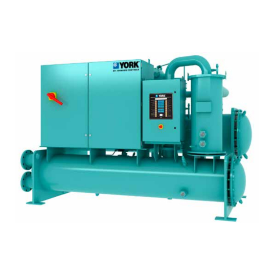
- Page 1 WATER-COOLED SCREW LIQUID CHILLERS INSTALLATION, OPERATION, MAINTENANCE Supersedes: 201.30-ICOM1 (318) Form 201.30-ICOM1 (519) 035-23322-000 MODEL YVWA SINGLE COMPRESSOR 50 HZ AND 60 HZ 125 - 200 TON 440 - 700 KW R-134A Issue Date: May 22, 2019...
- Page 2 FORM 201.30-ICOM1 (519) ISSUE DATE: 05/22/2019 IMPORTANT! READ BEFORE PROCEEDING! GENERAL SAFETY GUIDELINES This equipment is a relatively complicated apparatus. which it is situated, as well as severe personal injury or During rigging, installation, operation, maintenance, death to themselves and people at the site. or service, individuals may be exposed to certain com- This document is intended for use by owner-authorized ponents or conditions including, but not limited to:...
- Page 3 YVWA Chiller Start-up Checklist and Request for Authorized Start-up Technician 201.30-CL3 Field Connections and Control Wiring for YVWA Chiller 201.30-PW1 YVWA Renewal Parts 201.30-RP1 Limited Warranty 50.05-NM2 Shipping Damage Claims 50.15-NM Long-Term Storage Periodic Checklist and Logs for YR, YS, and YVWA Screw Chillers 50.20-CL9 JOHNSON CONTROLS...
- Page 4 FORM 201.30-ICOM1 (519) ISSUE DATE: 05/22/2019 SYSTEM NOMENCLATURE YVWA 0150 Unit Type X = No Selection YORK Variable Speed Q = Special Quote Screw Water-Cooled Chiller Design Series Mod Level Application Evaporator Tubes S = Standard Water Or CondeserTubes Chiller...
-
Page 5: Table Of Contents
Responsibility for Safety ..........................12 Misuse of Equipment ............................12 SECTION 2 - PRODUCT DESCRIPTION .......................15 Components ..............................15 Semi-Hermetic York Screw Compressors ..................... 19 Evaporator ..............................19 Condenser ..............................19 Refrigerant Circuit ............................19 Complete Factory Package ........................... 19 Electrical ................................ - Page 6 FORM 201.30-ICOM1 (519) ISSUE DATE: 05/22/2019 TABLE OF CONTENTS (CONT'D) Unit Piping ..............................57 Electrical Connection ............................57 Power Wiring ..............................57 Power Supply Wiring ............................57 115VAC Control Supply Transformer ......................57 Control Wiring ..............................57 System Inputs ..............................58 Analog Inputs ..............................
- Page 7 FORM 201.30-ICOM1 (519) ISSUE DATE: 05/22/2019 TABLE OF CONTENTS (CONT'D) SECTION 8 - TROUBLESHOOTING ........................147 Abnormal Operation, Analysis and Correction ..................... 147 Troubleshooting the Compressor and Oil Separation System ..............147 SECTION 9 - DECOMMISSIONING, DISMANTLING, AND DISPOSAL ............. 153 Temperature ..............................
- Page 8 LIST OF FIGURES FIGURE 1 - Emergency Shutdown Handle ......................13 FIGURE 2 - YVWA Chiller Major Components (Front View) ...................16 FIGURE 3 - YVWA Chiller Major Components (Rear View) ..................17 FIGURE 4 - Basic System Control and VSD System Architecture ................18 FIGURE 5 - Control Center User Interface ......................20...
- Page 9 FIGURE 58 - Manual Override and Print Key......................122 FIGURE 59 - Printer Cable Connection from YVWA Chiller to a Computer ............122 FIGURE 60 - Printer Cable Connection from YVWA Chiller to a Serial Printer ............. 123 FIGURE 61 - Sample Printout ..........................125 FIGURE 62 - System Switches and Service Keys ....................127...
- Page 10 TABLE 40 - Okidata OKIPOS 441 ........................123 TABLE 41 - Printout Types ............................124 TABLE 42 - Real Time Number Errors ........................129 TABLE 43 - Operation/Inspection /Maintenance Requirements for YVWA Chillers ..........131 TABLE 44 - Compressor Oil Limits ........................133 TABLE 45 - System Pressures ..........................140 TABLE 46 - Troubleshooting Guide ........................148...
-
Page 11: Section 1 - General Chiller Information And Safety
18 months from the date of shipment or 12 months from the date of start-up, whichever comes YORK YVWA chillers are manufactured to the highest first, unless labor or extended warranty has been pur- design and construction standards to ensure high per- chased as part of the contract. -
Page 12: Fluorinated Greenhouse Gases
FORM 201.30-ICOM1 (519) SECTION 1 - GENERAL CHILLER INFORMATION AND SAFETY ISSUE DATE: 05/22/2019 • GB/T 18430.1 - Water Chilling (Heat Pump) Pack- • Personal safety, the safety of other personnel, and ages Using The Vapor Compression Cycle - Part the equipment. -
Page 13: Figure 1 - Emergency Shutdown Handle
FORM 201.30-ICOM1 (519) SECTION 1 - GENERAL CHILLER INFORMATION AND SAFETY ISSUE DATE: 05/22/2019 Pressure Systems The unit contains refrigerant vapor and liquid under pres- sure, release of which can be a danger and cause injury. The user should make sure that care is taken during in- stallation, operation, and maintenance to avoid damage to the pressure system. - Page 14 FORM 201.30-ICOM1 (519) ISSUE DATE: 05/22/2019 THIS PAGE INTENTIONALLY LEFT BLANK. JOHNSON CONTROLS...
-
Page 15: Section 2 - Product Description
YORK YVWA chillers are designed for water or gly- COMPONENTS col cooling. All units are designed to be located in an The YVWA chiller, as shown in Figure 2 on page 16 equipment room unless the unit was ordered specially and Figure 3 on page 17, consists of: for outside applications. -
Page 16: Figure 2 - Yvwa Chiller Major Components (Front View)
ISSUE DATE: 05/22/2019 LD17364 1. Control Panel 5. Condenser 2. Variable Speed Drive (VSD) 6. Condenser Sight Glass 3. Oil Separator 7. Evaporator 4. Return Water Box 8. Condenser Water Nozzle FIGURE 2 - YVWA CHILLER MAJOR COMPONENTS (FRONT VIEW) JOHNSON CONTROLS... -
Page 17: Figure 3 - Yvwa Chiller Major Components (Rear View)
SECTION 2 - PRODUCT DESCRIPTION ISSUE DATE: 05/22/2019 LD17365 1. VSD 5. Liquid Level Sensor 2. Compressor 6. Liquid Line 3. Evaporator Sight Glass 7. Condenser 4. Evaporator Water Nozzle 8. Evaporator FIGURE 3 - YVWA CHILLER MAJOR COMPONENTS (REAR VIEW) JOHNSON CONTROLS... -
Page 18: Figure 4 - Basic System Control And Vsd System Architecture
FORM 201.30-ICOM1 (519) SECTION 2 - PRODUCT DESCRIPTION ISSUE DATE: 05/22/2019 INPUTS OUTPUTS Pressure Transducers (Relay Output Board) Temperature Sensors Switches Solenoids Liquid Flow Alarm CONTROL High Pressure Pump PANEL Start/Stop Compressor Heater (Chiller Control Level Run Status Board) Customer Supplied Contacts Microprocessor User Interface... -
Page 19: Semi-Hermetic York Screw Compressors
The YVWA compressor is one of evaporator and condenser to ensure each circuit func- the most efficient and reliable screw compressors in tions correctly. -
Page 20: Microcomputer Control Center
FORM 201.30-ICOM1 (519) SECTION 2 - PRODUCT DESCRIPTION ISSUE DATE: 05/22/2019 MICROCOMPUTER CONTROL CENTER The microcomputer control center, shown in Figure 5 on page 20, provides automatic control of chiller operation including compressor start/stop and load/un- load anti-recycle timers, condenser and chilled water (CHW) pumps, unit alarm contacts and run signal con- tacts. - Page 21 FORM 201.30-ICOM1 (519) SECTION 2 - PRODUCT DESCRIPTION ISSUE DATE: 05/22/2019 Double Thick Insulation 1-1/2 in. (38 mm) insulation servicing. Circuit breaker is sized to provide motor is available on the evaporator as a factory-installed op- branch, short circuit and ground fault protection for the tion.
-
Page 22: Figure 6 - Head Pressure Control System
The Head Pressure Control function provides an output YVWA Chillers are capable of operation with- control signal that will respond to a programmed mini- in a wide range of condenser water tempera- mum chiller differential pressure. -
Page 23: Section 3 - Handling, Storage, Installation And Reassembly
• Form 1 (shipped assembled with refrigerant and the assembly of its components. Refer to the charge) YVWA Installation Checklist (Form 201.30-CL1) for detailed instructions. Do not dismantle or un- • Form 2 (shipped assembled without refrigerant wrap the chiller for any reason unless advised by charge) a Johnson Controls representative. - Page 24 • All openings on the shells are closed and charged removed from the shells and skidded separately. with a 2-3 psig (115-122 kPa) holding charge of Form 7 YVWA chillers are shipped in the following as- dry nitrogen. semblies: • Hardware is added to the package with the miscel- laneous nuts, bolts, and fittings.
-
Page 25: Inspection, Damage, And Shortage
• If the unit is stored longer than six months, follow ny's inspection. the requirements from Long-Term Storage Peri- odic Checklist and Logs for YR, YS, and YVWA Johnson Controls will not be responsible Screw Chillers (Form 50.20-NM9). for any damage or loss of parts in ship- ment or at job site. -
Page 26: Lifting Weights
FORM 201.30-ICOM1 (519) SECTION 3 - HANDLING, STORAGE, INSTALLATION AND REASSEMBLY ISSUE DATE: 05/22/2019 LIFTING WEIGHTS A lifting diagram is placed on the chiller and the shipping package. For detailed unit weights and weight distribu- tion, refer to the data shipped in the chiller information packet and unit nameplate. TABLE 1 - UNIT WEIGHT APPROXIMATE UNIT WEIGHT SHIPPING... -
Page 27: Moving The Chiller For Forms 1 And 2
FORM 201.30-ICOM1 (519) SECTION 3 - HANDLING, STORAGE, INSTALLATION AND REASSEMBLY ISSUE DATE: 05/22/2019 MOVING THE CHILLER FOR FORMS 1 AND 2 RIGGING Prior to moving the unit, make sure that the installa- The complete standard unit (Forms 1 and 2) is shipped tion site is suitable for installing the unit and is easily without skids. -
Page 28: Foundation
FORM 201.30-ICOM1 (519) SECTION 3 - HANDLING, STORAGE, INSTALLATION AND REASSEMBLY ISSUE DATE: 05/22/2019 LOCATION TABLE 2 - SERVICE CLEARANCE REQUIRE- MENTS Locate the chiller in an indoor location with tempera- TUBE REMOVAL ADD MARINE ture ranges from 40°-110°F (4°-43°C) and adequate SHELL CODE SPACE WATER BOXES... -
Page 29: Installing Elastomeric Vibration Isolator Pads
FORM 201.30-ICOM1 (519) SECTION 3 - HANDLING, STORAGE, INSTALLATION AND REASSEMBLY ISSUE DATE: 05/22/2019 INSTALLING ELASTOMERIC VIBRATION ISOLATOR PADS Locate the elastomeric vibration isolator pads as shown The unit should be level within 0.25 in. (6 mm) from in Figure 9 on page 29 After placing the isolator one end to the other end, and from front to the rear. -
Page 30: Installing Optional Spring Isolators
FORM 201.30-ICOM1 (519) SECTION 3 - HANDLING, STORAGE, INSTALLATION AND REASSEMBLY ISSUE DATE: 05/22/2019 INSTALLING OPTIONAL SPRING ISOLATORS If ordered, four identical spring type isolator assemblies 4. After the unit is leveled, wedge and shim under are furnished with the unit as shown in Figure 10 on each corner to solidly support the unit in this posi- page 30. -
Page 31: Form 7 Reassembly
1. Determine the final location. Verify that the final 2. For wiring connections, refer to Field Con- location meets all of the minimum required clear- nections and Control Wiring for YVWA Chiller ances. Refer to Figure 8 on page 28. (201.30-PW2). -
Page 32: Table 4 - Torque Specification
FORM 201.30-ICOM1 (519) SECTION 3 - HANDLING, STORAGE, INSTALLATION AND REASSEMBLY ISSUE DATE: 05/22/2019 TABLE 4 - TORQUE SPECIFICATION UNIT TORQUE VALUE YORK PART ITEM DESCRIPTION QUANTITY NUMBER NUMBER FT-LBS. END SHEETS (CON-EVAP ASSY) HCS5 0.625-11 X 2.500 GR 5 ZN... -
Page 33: Figure 11 - Rigging The Evaporator
FORM 201.30-ICOM1 (519) SECTION 3 - HANDLING, STORAGE, INSTALLATION AND REASSEMBLY ISSUE DATE: 05/22/2019 Installing the Evaporator Use the following instructions to install the evaporator 1. Attach the rigging chains from the overhead lift to as shown in Figure 11 on page 33. the four lifting holes of the evaporator (two at the top of each end sheet). -
Page 34: Figure 12 - Condenser Rigging
FORM 201.30-ICOM1 (519) SECTION 3 - HANDLING, STORAGE, INSTALLATION AND REASSEMBLY ISSUE DATE: 05/22/2019 Rigging and Installing the Condenser 1. Attach the rigging chains from the overhead lift to Use the following instructions to install the condenser the four lifting holes of the condenser (two at the as shown in Figure 12 on page 34. -
Page 35: Figure 13 - Isolator Installation
FORM 201.30-ICOM1 (519) SECTION 3 - HANDLING, STORAGE, INSTALLATION AND REASSEMBLY ISSUE DATE: 05/22/2019 Installing the Pads or Spring Isolators Use the following instructions to install the elastomeric 2. With an adequate lifting device lift the unit slight- pads or optional spring isolators as shown on on page ly off the ground to determine adjustments neces- sary to keep the unit level. - Page 36 FORM 201.30-ICOM1 (519) SECTION 3 - HANDLING, STORAGE, INSTALLATION AND REASSEMBLY ISSUE DATE: 05/22/2019 LD16471 FIGURE 12 - ISOLATOR INSTALLATION (CONT'D) JOHNSON CONTROLS...
-
Page 37: Figure 14 - Heat Exchanger Shipping Brackets
FORM 201.30-ICOM1 (519) SECTION 3 - HANDLING, STORAGE, INSTALLATION AND REASSEMBLY ISSUE DATE: 05/22/2019 Installing the Heat Exchanger Piping Connect the economizer heat exchanger liquid outlet Use the following instructions after the temporary ship- ping brackets supporting the heat exchanger piping has pipes to the economizer on the evaporator, using the been removed as shown in Figure 14 on page 37. -
Page 38: Figure 16 - Liquid Injection Piping
FORM 201.30-ICOM1 (519) SECTION 3 - HANDLING, STORAGE, INSTALLATION AND REASSEMBLY ISSUE DATE: 05/22/2019 Installing the Liquid Injection Piping Installing Oil Return Piping If equipped, install the optional liquid injection piping Install the oil return and piping between the filter drier to the suction line on the evaporator and to the heat at the oil eductor and to port in the bottom of the evap- exchanger piping on each side of the chiller, using the... -
Page 39: Figure 18 - Driveline (Compressor/Motor) Assembly
FORM 201.30-ICOM1 (519) SECTION 3 - HANDLING, STORAGE, INSTALLATION AND REASSEMBLY ISSUE DATE: 05/22/2019 Installing Driveline Assembly Specific shim pads will be bolted to the Use the following instructions to install the driveline compressor supports to satisfy the align- (compressor/motor) assembly as shown in Figure 18 ment between the compressor and system on page 39. -
Page 40: Table 8 - Oil Separator Weight And Dimensions On Single Compressor Units
FORM 201.30-ICOM1 (519) SECTION 3 - HANDLING, STORAGE, INSTALLATION AND REASSEMBLY ISSUE DATE: 05/22/2019 Installing Oil Separator 2. Bolt the line to the flange on the oil separator and Use the following instructions to install the oil separator, to compressor discharge using the proper gaskets as shown in Figure 19 on page 41. -
Page 41: Figure 19 - Oil Separator Discharge Piping On Single Compressor Units
FORM 201.30-ICOM1 (519) SECTION 3 - HANDLING, STORAGE, INSTALLATION AND REASSEMBLY ISSUE DATE: 05/22/2019 With Isolation Ball Valve LD17759 Refer to Table 4 on page 32 for Torque Specifications. FIGURE 19 - OIL SEPARATOR DISCHARGE PIPING ON SINGLE COMPRESSOR UNITS JOHNSON CONTROLS... -
Page 42: Figure 20 - Transducer, Eductor And Oil Return Piping
FORM 201.30-ICOM1 (519) SECTION 3 - HANDLING, STORAGE, INSTALLATION AND REASSEMBLY ISSUE DATE: 05/22/2019 Oil Return Oil Return Pressure Pressure from Eductor from Eductor Transducer Transducer Oil Return Oil Return from Oil Separator from Oil Separator 136/145 Compressor Ports 151 Compressor Ports LD17760 Refer to Table 4 on page 32 for Torque Specifications. -
Page 43: Table 9 - Vsd Weight And Dimensions
FORM 201.30-ICOM1 (519) SECTION 3 - HANDLING, STORAGE, INSTALLATION AND REASSEMBLY ISSUE DATE: 05/22/2019 Installing Variable Speed Drive (VSD) Use the following instructions to install the VSD as 3. Install the VSD to the plate with the proper hard- ware. shown in Figure 22 on page 44. -
Page 44: Figure 22 - Variable Speed Drive (Vsd)
FORM 201.30-ICOM1 (519) SECTION 3 - HANDLING, STORAGE, INSTALLATION AND REASSEMBLY ISSUE DATE: 05/22/2019 65° Min. Lifting Holes LD17762 Refer to Table 4 on page 32 for Torque Specifications. FIGURE 22 - VARIABLE SPEED DRIVE (VSD) Installing Control Panel Connecting VSD Cooling Hoses Use the following instructions to install the Control Connect the cooling hoses from the VSD to the water Panel as shown in Figure 23 on page 45. -
Page 45: Figure 23 - Control Panel
FORM 201.30-ICOM1 (519) SECTION 3 - HANDLING, STORAGE, INSTALLATION AND REASSEMBLY ISSUE DATE: 05/22/2019 Refer to Table 4 on page 32 for Torque Specifications. FIGURE 23 - CONTROL PANEL Detail A LD17764 CONDENSER LD17763 FIGURE 24 - VSD COOLING HOSES JOHNSON CONTROLS... -
Page 46: Piping Joint Assembly
FORM 201.30-ICOM1 (519) SECTION 3 - HANDLING, STORAGE, INSTALLATION AND REASSEMBLY ISSUE DATE: 05/22/2019 Evaporator Condenser Evaporator Condenser Only be used for heat pump unit Only be used for standard air-conditioning ice storage unit and brine unit LD18956 FIGURE 25 - ALTERNATE PIPING FOR VSD TABLE 10 - ASSEMBLY COMPOUNDS LOCTITE GRADE DESCRIPTION... -
Page 47: Gasket Joints
FORM 201.30-ICOM1 (519) SECTION 3 - HANDLING, STORAGE, INSTALLATION AND REASSEMBLY ISSUE DATE: 05/22/2019 PROCEDURES GASKET JOINTS Cleaning Assembling Gasket Joints Clean the parts visually contaminated with oil, grease, Use the following instructions to assemble the gasket or dirt with a generous spray of cleaner 7070. Wipe joints. -
Page 48: Torque Values
FORM 201.30-ICOM1 (519) SECTION 3 - HANDLING, STORAGE, INSTALLATION AND REASSEMBLY ISSUE DATE: 05/22/2019 Torque Values Sealing is thus affected and maintained by the O-ring All threaded fasteners shall be torqued to the values compression which results from the clamping force shown in Table 13 on page 48 for the appropriate generated by tightening. -
Page 49: Figure 28 - Back Off Locknut
FORM 201.30-ICOM1 (519) SECTION 3 - HANDLING, STORAGE, INSTALLATION AND REASSEMBLY ISSUE DATE: 05/22/2019 Back off locknut as far as possible. Make sure back-up 7. Inspect to ensure that O-ring is NOT pinched and washer is NOT loose and is pushed up as far as pos- the back-up washer seats flat on face of port. -
Page 50: Brazed Joints
FORM 201.30-ICOM1 (519) SECTION 3 - HANDLING, STORAGE, INSTALLATION AND REASSEMBLY ISSUE DATE: 05/22/2019 Assembly of O-ring Face Seal Fittings BRAZED JOINTS For personnel safety: No brazing or heat The male end and female nut of face seal fittings have working shall be done unless the refriger- UN/UNF straight threads. -
Page 51: Figure 32 - Brazed Joints
FORM 201.30-ICOM1 (519) SECTION 3 - HANDLING, STORAGE, INSTALLATION AND REASSEMBLY ISSUE DATE: 05/22/2019 TABLE 15 - O-RING ASSEMBLY TORQUE SPECIFICATIONS SAE STRAIGHT TUBE SAE STRAIGHT THREAD FACE SEAL TUBE-SIDE FACE SEAL TUBE- THREAD TORQUE SIZE (IN) SIZE (O-RING P/N) THREAD SIZE (O-RING P/N) SIDE TORQUE (FT-LB) (FT-LB) -
Page 52: Piping Connections
FORM 201.30-ICOM1 (519) SECTION 3 - HANDLING, STORAGE, INSTALLATION AND REASSEMBLY ISSUE DATE: 05/22/2019 PIPING CONNECTIONS After the unit is leveled (and wedged in place for op- The maximum flow rate and pressure drop tional spring isolators) the piping connections may be for the condenser and evaporator must not fabricated. -
Page 53: Water Treatment
YVWA chillers are Aerated, brackish, or salt water is not recommended designed to function efficiently when condenser water for use in the water systems. -
Page 54: Pipework Arrangement
RATIO RANGE Air Conditioning 5-8 (min of 5) 5.5-8.8 (min of 3.3) The YVWA chiller line has a maximum leaving Process 7-11 (min of 7) 7.7-12.3 (min of 4.4) water temperature of 60°F (15.6°C). Where process Install a tank or increase pipe sizes to provide suffi- applications require a chilled water temperature higher cient water volume. -
Page 55: Nozzle Connections
American the Johnson Controls Sales Office for more informa- Society of Heating, Refrigeration and Air Conditioning tion about successfully applying YVWA chillers. Engineers Standard 15 (ASHRAE 15) in North Amer- ica, or PED code in Europe. Valve specifications are NOZZLE CONNECTIONS shown in Table 19 on page 56. -
Page 56: Figure 37 - Typical Components Of Relief Piping
FORM 201.30-ICOM1 (519) SECTION 3 - HANDLING, STORAGE, INSTALLATION AND REASSEMBLY ISSUE DATE: 05/22/2019 When installing relief piping an ANSI flange or a piping union must be used to make a servicable piping connection. Horizontal Vertical Compressed Mis-aligned Offset When installing relief piping there must NOT be any piping strain. -
Page 57: Unit Piping
FORM 201.30-ICOM1 (519) SECTION 3 - HANDLING, STORAGE, INSTALLATION AND REASSEMBLY ISSUE DATE: 05/22/2019 UNIT PIPING POWER SUPPLY WIRING Compressor lubricant piping and system refrigerant Units require one 3-phase supply, plus earth. Connect: piping are factory installed on all units shipped assem- •... -
Page 58: System Inputs
FORM 201.30-ICOM1 (519) SECTION 3 - HANDLING, STORAGE, INSTALLATION AND REASSEMBLY ISSUE DATE: 05/22/2019 Run Contact TABLE 20 - SYSTEM INPUT CONNECTIONS INPUT 1TB TERMINALS Terminals 21 and 22 on 1TB close to indicate that a system is running. Chilled Liquid Flow Switch 2 and 13 Condenser Liquid Flow Switch 2 and 12... - Page 59 FORM 201.30-ICOM1 (519) SECTION 3 - HANDLING, STORAGE, INSTALLATION AND REASSEMBLY ISSUE DATE: 05/22/2019 0–20 or 4-20 mA Reset Input 0-10 or 2-10 VDC Reset Input A 0 or 4 mA signal produces a 0°F (0°C) reset. A 20 A 0 or 2 VDC signal produces a 0°F (0°C) reset. mA signal produces 100% (max.) reset (SETPOINTS A 10 VDC signal produces a 100% (max.) reset key).
- Page 60 FORM 201.30-ICOM1 (519) SECTION 3 - HANDLING, STORAGE, INSTALLATION AND REASSEMBLY ISSUE DATE: 05/22/2019 Supersedes: 201.30-CL1 (513) Form 201.30-CL1 (417) MODEL – YVWA INSTALLATION CHECKLIST AND REQUEST FOR AUTHORIZED START-UP TECHNICIAN CUSTOMER: _________________________________ JOB NAME: _________________________________ ADDRESS: __________________________________ LOCATION: _________________________________...
- Page 61 6. Connect the following optional analog inputs to F. CONDITIONS their respective terminals of 1TB Terminal Block 1. YORK oil for compressor available ....a. Leaving Chilled and Condenser Temperature 2. Cooling load available for testing and operating Reset Control - Terminals 17 and 18 .....
-
Page 62: Figure 38 - Power Connections
FORM 201.30-ICOM1 (519) SECTION 3 - HANDLING, STORAGE, INSTALLATION AND REASSEMBLY ISSUE DATE: 05/22/2019 FIELD PROVIDED UNIT POWER SUPPLY SEE NOTE 1 VSD CONTROL PANEL STANDARD UNIT CONTROLS CONTROL TRANSFORMER NON-FUSED DISCONNECT SWITCH LINE REACTOR CIRCUIT BREAKER OPTION AVAILABLE INVERTER NOTES: ------- Dashed Line = Field Provided Wiring LD16428A... -
Page 63: Table 21 - Lug Data (Ul/Asme/Ce) - Pin 22/Power Field
FORM 201.30-ICOM1 (519) SECTION 3 - HANDLING, STORAGE, INSTALLATION AND REASSEMBLY ISSUE DATE: 05/22/2019 TABLE 21 - LUG DATA (UL/ASME/CE) - PIN 22/POWER FIELD NON-FUSED VSD DETAILS TERMINAL BLOCK CIRCUIT BREAKER DISCONNECT SWITCH WIRES WIRES WIRES INPUT INPUT LUG/ LUG/ LUG/ WIRE WIRE... - Page 64 FORM 201.30-ICOM1 (519) ISSUE DATE: 05/22/2019 THIS PAGE INTENTIONALLY LEFT BLANK. JOHNSON CONTROLS...
-
Page 65: Section 4 - Technical Data
FORM 201.30-ICOM1 (519) ISSUE DATE: 05/22/2019 SECTION 4 - TECHNICAL DATA TABLE 24 - COMPLETE PIN NUMBER DESCRIPTION DESCRIPTION OPTIONS OPTIONS DESCRIPTION MODEL York COMPRESSOR TYPE Variable Speed Screw CHILLER TYPE Water-cooled Chiller DESIGN SERIES Design Series Evaporator Sizes EVAPORATOR MODEL... - Page 66 FORM 201.30-ICOM1 (519) SECTION 4 - TECHNICAL DATA ISSUE DATE: 05/22/2019 TABLE 24 - COMPLETE PIN NUMBER DESCRIPTION (CONT'D) DESCRIPTION OPTIONS OPTIONS DESCRIPTION 380/3/60 460/3/60 20-21 VOLTAGE 380/3/50 400/3/50 415/3/50 Lockable NF Disconnect Switch Lockable Circuit Breaker POWER FIELD Supply Terminal Block Special Quote No Selection HARMONIC FILTER...
- Page 67 FORM 201.30-ICOM1 (519) SECTION 4 - TECHNICAL DATA ISSUE DATE: 05/22/2019 TABLE 24 - COMPLETE PIN NUMBER DESCRIPTION (CONT'D) DESCRIPTION OPTIONS OPTIONS DESCRIPTION Chinese Safety Code (GB) European Safety Code (CE) SAFETY CODE NA Safety Code (cUL/cETL) Special Quote No Selection 32-35 FUTURE OPTIONS Special Quote...
- Page 68 FORM 201.30-ICOM1 (519) SECTION 4 - TECHNICAL DATA ISSUE DATE: 05/22/2019 TABLE 24 - COMPLETE PIN NUMBER DESCRIPTION (CONT'D) DESCRIPTION OPTIONS OPTIONS DESCRIPTION None 3/4" insulation evaporator 1 1/2" insulation evaporator THERMAL INSULATION 3/4" insulation evap and cond 1 1/2" ins evap and 3/4" cond Special Quote GB Pressure Vessel Codes PED Pressure Vessel Codes...
- Page 69 FORM 201.30-ICOM1 (519) SECTION 4 - TECHNICAL DATA ISSUE DATE: 05/22/2019 TABLE 24 - COMPLETE PIN NUMBER DESCRIPTION (CONT'D) DESCRIPTION OPTIONS OPTIONS DESCRIPTION Water Calcium Chloride Sodium Chloride EVAPORATOR FLUID Ethylene Glycol Propylene Glycol Special Quote No Selection FUTURE OPTIONS Special Quote CLWT Temperature CONDENSER LEAVING WATER...
- Page 70 FORM 201.30-ICOM1 (519) SECTION 4 - TECHNICAL DATA ISSUE DATE: 05/22/2019 TABLE 24 - COMPLETE PIN NUMBER DESCRIPTION (CONT'D) DESCRIPTION OPTIONS OPTIONS DESCRIPTION Water Calcium Chloride Sodium Chloride CONDENSER FLUID Ethylene Glycol Propylene Glycol Special Quote 235 PSIG (1.62 MPa) CONDENSER SHELL SIDE DESIGN PRESSURE 388 PSIG (2.68 MPa)
- Page 71 FORM 201.30-ICOM1 (519) SECTION 4 - TECHNICAL DATA ISSUE DATE: 05/22/2019 TABLE 24 - COMPLETE PIN NUMBER DESCRIPTION (CONT'D) DESCRIPTION OPTIONS OPTIONS DESCRIPTION No SR Documents Monterrey base document Monterrey base & materials doc Sabadell base document Sabadell base & optional doc SR DOCUMENTS Wuxi base document Wuxi base &...
-
Page 72: Single Compressor Unit Dimensions
FORM 201.30-ICOM1 (519) SECTION 4 - TECHNICAL DATA ISSUE DATE: 05/22/2019 SINGLE COMPRESSOR UNIT DIMENSIONS TOP VIEW LD16476a SIDE VIEW FRONT VIEW LD16476b LD16476d FIGURE 39 - SINGLE COMPRESSOR UNIT DIMENSIONS JOHNSON CONTROLS... - Page 73 FORM 201.30-ICOM1 (519) SECTION 4 - TECHNICAL DATA ISSUE DATE: 05/22/2019 EVAPORATOR AND CONDENSER SHELL CODES IN (MM) DIMENSIONS SINGLE 145/151 DUAL 136/145 8ˊ (2438) 10ˊ (3048) 12ˊ (3658) 12' (3658) 14' (4268) 6ˊ-11/16" (1846) 6ˊ-11/16" (1846) 6ˊ-11/16" (1846) 6'-3/4" (1844) 6'-3/4"...
-
Page 74: Dimensions Of Evaporator Nozzle Arrangements
FORM 201.30-ICOM1 (519) SECTION 4 - TECHNICAL DATA ISSUE DATE: 05/22/2019 DIMENSIONS OF EVAPORATOR NOZZLE ARRANGEMENTS NOZZLE ARRANGEMENTS EVAPORATOR (PIN 5,6) NUMBER OF PASSES LD16477a FIGURE 40 - EVAPORATORS - COMPACT WATER BOXES (2-PASS) NOZZLE ARRANGEMENTS EVAPORATOR (PIN 5,6) NUMBER OF PASSES LD16477b FIGURE 41 - EVAPORATORS - COMPACT WATER BOXES (3-PASS) -
Page 75: Dimensions Of Condenser Nozzle Arrangements
FORM 201.30-ICOM1 (519) SECTION 4 - TECHNICAL DATA ISSUE DATE: 05/22/2019 DIMENSIONS OF CONDENSER NOZZLE ARRANGEMENTS NOZZLE ARRANGEMENTS CONDENSER (PIN 7,8) NUMBER OF PASSES LD16478a FIGURE 42 - CONDENSERS - COMPACT WATER BOXES (1-PASS) NOZZLE ARRANGEMENTS CONDENSER (PIN 7,8) NUMBER OF PASSES LD16478b FIGURE 43 - CONDENSERS - COMPACT WATER BOXES (2-PASS) -
Page 76: Table 27 - Water Flow Rate Limits Gpm (L/S) (Based Upon Standard Tubes At Design Full Load Conditions)
FORM 201.30-ICOM1 (519) SECTION 4 - TECHNICAL DATA ISSUE DATE: 05/22/2019 TABLE 27 - WATER FLOW RATE LIMITS GPM (L/S) (BASED UPON STANDARD TUBES AT DESIGN FULL LOAD CONDITIONS) EVAPORATOR CONDENSER PIN 5, 6 2 PASS 3 PASS PIN 7, 8 1 PASS 2 PASS 3 PASS... -
Page 77: Section 5 - Commissioning
FORM 201.30-ICOM1 (519) ISSUE DATE: 05/22/2019 SECTION 5 - COMMISSIONING PREPARATION Service and Oil Line Valves Commissioning of this unit should only If valves are of the back-seat type, open them fully be carried out by Johnson Controls au- (counterclockwise), then close one turn of the stem. thorized personnel. - Page 78 FORM 201.30-ICOM1 (519) SECTION 5 - COMMISSIONING ISSUE DATE: 05/22/2019 Supersedes: 201.30-CL3 (215) Form 201.30-CL3 (417) MODEL – YVWA START-UP CHECKLIST CUSTOMER: _________________________________ JOB NAME: _________________________________ ADDRESS: __________________________________ LOCATION: _________________________________ PHONE: _____________________________________ CUSTOMER ORDER NO: ______________________ JCI TEL NO: ____________________ JCI ORDER NO: ________________ JCI CONTRACT NO: ____________...
- Page 79 FORM 201.30-ICOM1 (519) SECTION 5 - COMMISSIONING ISSUE DATE: 05/22/2019 FORM 201.30-CL3 ISSUE DATE: 4/20/2017 18. Check whenever the pump contacts are used, ADJUSTMENT SETTING VALUE the coil of the pump starter should be suppressed Long Time Pickup IR~ with an RC suppressor (P/N 031-00808-000)..Long Time Delay TLD(S) LONG B.
- Page 80 FORM 201.30-ICOM1 (519) SECTION 5 - COMMISSIONING ISSUE DATE: 05/22/2019 FORM 201.30-CL3 ISSUE DATE: 4/20/2017 8. Press the STATUS key. If the following UNIT 5. Leaving Condenser Liquid WARNING message appears, immediately Temp Control Range = _________________°F (°C) contact Johnson Controls Product Technical 6.
- Page 81 Switch the UNIT switch to the OFF position..........P.O. Box 1592, York, Pennsylvania USA 17405-1592 800-861-1001 Subject to change without notice. Printed in USA Copyright © by Johnson Controls 2017 www.johnsoncontrols.com...
- Page 82 FORM 201.30-ICOM1 (519) ISSUE DATE: 05/22/2019 THIS PAGE INTENTIONALLY LEFT BLANK. JOHNSON CONTROLS...
-
Page 83: Section 6 - Operation
FORM 201.30-ICOM1 (519) ISSUE DATE: 05/22/2019 SECTION 6 - OPERATION Keypad OPERATING CONTROLS DISPLAY An operator keypad allows complete control of the sys- tem from a central location. Access the following command keys on the left and right side of the keypad: •... -
Page 84: Basic Operating Sequence
FORM 201.30-ICOM1 (519) SECTION 6 - OPERATION ISSUE DATE: 05/22/2019 Use the ▲,▼,◄, and ► keys to see the multiple dis- BASIC OPERATING SEQUENCE plays under a key. Once the ▲ ▼ keys are pressed and Start Sequence and Loading used for scrolling, pressing the original data key will return to the first display message displayed under the To start the chiller, the following conditions must be... -
Page 85: Figure 46 - Control Operation
FORM 201.30-ICOM1 (519) SECTION 6 - OPERATION ISSUE DATE: 05/22/2019 • A low leaving chilled liquid temperature fault Remote Run Permissive Input occurs. The run permissive switches must have electrical con- • The VSD is requested to precharge for a run. tinuity to Terminal 2 to permit the chiller to run. -
Page 86: Table 28 - Load Limiting Values
FORM 201.30-ICOM1 (519) SECTION 6 - OPERATION ISSUE DATE: 05/22/2019 TABLE 28 - LOAD LIMITING VALUES PARAMETER X POINT Y POINT Z POINT (X AXIS UNITS) Active Current Limit Setting – Active Current Limit Setting + MOTOR CURRENT (%FLA) Active Current Limit Setting 2% FLA 5% FLA High Discharge Pressure... - Page 87 FORM 201.30-ICOM1 (519) SECTION 6 - OPERATION ISSUE DATE: 05/22/2019 Once a change to the input is registered, a timer setpoint will be ignored, and the LCLT setpoint is is set to the value of the REMOTE INPUTS SER- set to the local setpoint. VICE TIME as programmable under the UNIT The minimum and maximum allowable reset val- SETUP mode at the factory for the 15 minutes...
-
Page 88: User Interface
FORM 201.30-ICOM1 (519) SECTION 6 - OPERATION ISSUE DATE: 05/22/2019 • Remote Current Limit Analog Reset: Set the USER INTERFACE CURRENT LIMIT setpoint via the REMOTE The keys, detailed in the following pages, provide vari- CURRENT LIMIT analog input. A zero signal in- ous displays of unit related data. -
Page 89: Figure 47 - Status Key
FORM 201.30-ICOM1 (519) SECTION 6 - OPERATION ISSUE DATE: 05/22/2019 STATUS KEY STATUS LD19539 FIGURE 47 - STATUS KEY Press the STATUS key to display the current whole or could be displayed at any time on a one-compressor individual system's operational status, which includes: chiller. - Page 90 FORM 201.30-ICOM1 (519) SECTION 6 - OPERATION ISSUE DATE: 05/22/2019 The flow switch is open, which is preventing the unit OPD MITIGATION from running. There is a one second delay until the unit shuts down. OPD is Oil Pressure Differential. Condenser level con- trol is repositioning the level setpoint to reduce evapo- UNIT STATUS rator pressure and overcome low differential pressure...
-
Page 91: Fault Messages
FORM 201.30-ICOM1 (519) SECTION 6 - OPERATION ISSUE DATE: 05/22/2019 FAULT MESSAGES system problems since it allows the service technician A number of possible fault messages may appear when to view operating parameters prior to a unit fault. De- the STATUS key is pressed. Whenever a fault message tails on the new datalogging capability are explained appears, the safety thresholds on the unit have been ex- in the OPTIONS Key area of this manual. -
Page 92: Figure 48 - New 331-03478-Xxx Microboard
FORM 201.30-ICOM1 (519) SECTION 6 - OPERATION ISSUE DATE: 05/22/2019 TP4 +12V TP10 +24V TP5 +15V TP1 GND Port 1 Future Native U26 Port 1 RS-485 Driver +3.3V U18 VSD RS-485 Driver Card VSD RX VSD TX RS-232 to Printer Port 2 U23 Port 2 Port 2... -
Page 93: Program Update
FORM 201.30-ICOM1 (519) SECTION 6 - OPERATION ISSUE DATE: 05/22/2019 Communication Ports TB3 Port 1 Native BAS RS-485. 5. Press the OPTIONS Key and then press the Down Arrow Key until FLASH CARD UPDATE DIS- SW1 RS-485 Biasing Switch for Port. Set to ON if ABLED is displayed. -
Page 94: Data Logging
FORM 201.30-ICOM1 (519) SECTION 6 - OPERATION ISSUE DATE: 05/22/2019 DATA LOGGING Next press the Right Arrow key to select ON then press A 2GB SD card (p/n 031-03466-000) may be inserted the ENTER key to start the Data Log. A 2GB SD card into the 03478 IPUII SD card slot to record the chiller will hold about 8 months worth of data. -
Page 95: Table 31 - Unit Warnings
FORM 201.30-ICOM1 (519) SECTION 6 - OPERATION ISSUE DATE: 05/22/2019 TABLE 31 - UNIT WARNINGS MESSAGE DESCRIPTION This message alerts low oil flow, possibly from a clogged oil filter. A system will not shutdown when its HIGH OIL FILTER DIFFERENTIAL PRESSURE (Oil Pressure - Discharge Pressure) OIL FILTER CLOGGED rises above the programmable setpoint (10 to 100 psid, default 20 psid). - Page 96 FORM 201.30-ICOM1 (519) SECTION 6 - OPERATION ISSUE DATE: 05/22/2019 Unit Safeties (Faults) First Fault Code Unit safeties (faults), as shown in Table 32 on page The first fault code will be set for the fault that initiated 97, are: the system shutdown.
-
Page 97: Table 32 - Unit Safeties (Faults)
FORM 201.30-ICOM1 (519) SECTION 6 - OPERATION ISSUE DATE: 05/22/2019 TABLE 32 - UNIT SAFETIES (FAULTS) MESSAGE DESCRIPTION Software-Initiated Fault - The voltage magnitude of each half of the DC bus shall remain within UNIT YYYYYYY +/- 100 VDC of the total DC bus voltage divided by two. If the magnitude exceeds the +/- 100 volt window the unit shall initiate a shutdown. - Page 98 FORM 201.30-ICOM1 (519) SECTION 6 - OPERATION ISSUE DATE: 05/22/2019 TABLE 32 - UNIT SAFETIES FAULTS (CONT'D) MESSAGE DESCRIPTION The voltage magnitude of each half of the DC bus shall remain within +/- 100 VDC of the total UNIT YYYYYYY DC bus voltage divided by two.
-
Page 99: Table 33 - System Safeties (Faults)
FORM 201.30-ICOM1 (519) SECTION 6 - OPERATION ISSUE DATE: 05/22/2019 TABLE 32 - UNIT SAFETIES FAULTS (CONT'D) MESSAGE DESCRIPTION Hardware-Initiated Fault - The various DC power supplies which power the logic board are monitored via hardware located on the logic board. If any power supply falls outside its allowable limits, the unit initiates a shutdown. - Page 100 FORM 201.30-ICOM1 (519) SECTION 6 - OPERATION ISSUE DATE: 05/22/2019 TABLE 33 - SYSTEM SAFETIES FAULTS (CONT'D) MESSAGE DESCRIPTION Software-Initiated Fault - A system will fault and shut down with a ramped shutdown when the high discharge pressure rises above 333 psig (2300 kPa) for 0.5 seconds. The system will be allowed to restart when the discharge pressure falls to 293 psig (20.2 kPa).
-
Page 101: Table 34 - Hpco Mechanical Cutouts
FORM 201.30-ICOM1 (519) SECTION 6 - OPERATION ISSUE DATE: 05/22/2019 TABLE 33 - SYSTEM SAFETIES FAULTS (CONT'D) MESSAGE DESCRIPTION Hardware-Initiated Fault - The mechanical High Pressure Cutout (HPCO) protects the system from experiencing dangerously high discharge pressure. A system will fault and shut down immediately when the mechanical high pressure cutout contacts open. - Page 102 FORM 201.30-ICOM1 (519) SECTION 6 - OPERATION ISSUE DATE: 05/22/2019 TABLE 33 - SYSTEM SAFETIES FAULTS (CONT'D) MESSAGE DESCRIPTION This fault protects against excessive liquid refrigerant carryover from the economizer, in cases which may be a result of EEV, sensor or other problems. It also protects the system compressor from liquid refrigerant flooding back from the economizer feed line, in cases where the economizer valve fails to close.
- Page 103 FORM 201.30-ICOM1 (519) SECTION 6 - OPERATION ISSUE DATE: 05/22/2019 TABLE 33 - SYSTEM SAFETIES FAULTS (CONT'D) MESSAGE DESCRIPTION This fault is considered active when SMART FREEZE is turned on via the enable/disable setting, and the active LCHLT control setpoint is less than or equal to 38.0°F (3.3°C). SMART FREEZE can only be enabled or disabled while the chiller is stopped, and is only available in water applications.
-
Page 104: Figure 49 - Unit Data Key
FORM 201.30-ICOM1 (519) SECTION 6 - OPERATION ISSUE DATE: 05/22/2019 UNIT DATA KEY UNIT DATA KEY LD19539 FIGURE 49 - UNIT DATA KEY The UNIT DATA key displays unit temperatures, and UNIT EVAP/COND PUMP RUN = ON OR OFF related data. Select the displays, which are listed se- VSD COOLANT AUX PUMP = ON OR OFF quentially, by repeatedly pressing the UNIT DATA, or If the control is enabled, the VSD coolant aux pump... -
Page 105: Figure 50 - System Data Key
FORM 201.30-ICOM1 (519) SECTION 6 - OPERATION ISSUE DATE: 05/22/2019 SYSTEM DATA KEY SYSTEM DATA KEY LD19539 FIGURE 50 - SYSTEM DATA KEY System Data Key Operation The SYSTEM DATA key gives access to SYSTEM op- If the evaporator refrigerant temperature sensor is re- erating parameters. -
Page 106: Table 36 - Sensor Minimum/Maximum Outputs
FORM 201.30-ICOM1 (519) SECTION 6 - OPERATION ISSUE DATE: 05/22/2019 Display, if control is enabled. Sensor Displays Table 36 on page 106 lists all the sensors attached VI STEP SOLENOID 1 = ON OR OFF to the control board associated with SYSTEM DATA VI STEP SOLENOID 2 = ON OR OFF keys. -
Page 107: Figure 51 - Vsd Data And Operating Hours/Start Counter Keys
FORM 201.30-ICOM1 (519) SECTION 6 - OPERATION ISSUE DATE: 05/22/2019 VSD DATA AND OPERATING HOURS/START COUNTER KEYS VSD DATA OPERATING HOURS/START COUNTER KEY LD19539 FIGURE 51 - VSD DATA AND OPERATING HOURS/START COUNTER KEYS The VSD DATA key provides multiple displays of VSD IGBT BASEPLATE TEMPS T1 = ### °F VSD operating data, such as voltages and currents. -
Page 108: Figure 52 - History Key
FORM 201.30-ICOM1 (519) SECTION 6 - OPERATION ISSUE DATE: 05/22/2019 HISTORY KEY HISTORY LD19539 FIGURE 52 - HISTORY KEY For all faults generated by the control To access the HISTORY FAULT or NORMAL SHUT- panel, a snapshot of all system data will DOWN information, use the following steps: be stored immediately before shutting 1. - Page 109 FORM 201.30-ICOM1 (519) SECTION 6 - OPERATION ISSUE DATE: 05/22/2019 If there are no ALL FAULTS for the current history, • OPTIONS on page 118 the following message will be displayed for the ALL • Display Language FAULTS screen. • Liquid Type, etc. FAULT HIST ## ALL FAULTS •...
-
Page 110: Figure 53 - Setpoints Key
FORM 201.30-ICOM1 (519) SECTION 6 - OPERATION ISSUE DATE: 05/22/2019 SETPOINTS KEY SETPOINTS KEY LD19539 FIGURE 53 - SETPOINTS KEY Press the SETPOINTS key to program: This message (above) will display the remote setpoint and control, which automatically updates. If there is •... -
Page 111: Figure 54 - Setpoint High And Low Limits Defined By Control Range (Cr)
FORM 201.30-ICOM1 (519) SECTION 6 - OPERATION ISSUE DATE: 05/22/2019 TABLE 37 - SETPOINT VALUES PROGRAM VALUE MODE LOW LIMIT HIGH LIMIT DEFAULT 38.0°F 60.0°F 44.0°F Water Cooling 3.3°C 15.6°C 6.7°C Leaving Chilled Liquid Temp Setpoint 8.0°F 70.0°F 44.0°F Glycol Cooling -13.3°C 15.6°C 6.7°C... -
Page 112: Figure 55 - Program Key
FORM 201.30-ICOM1 (519) SECTION 6 - OPERATION ISSUE DATE: 05/22/2019 PROGRAM KEY PROGRAM KEY LD19539 FIGURE 55 - PROGRAM KEY Press the PROGRAM key to modify the following nu- PROGRAM ◄DEF 103 LO 30 HI 103 meric operating parameters, which are displayed when MOTOR CURRENT LIMIT = ###% FLA this key is pressed. -
Page 113: Table 38 - Program Limits
Unit "SETUP MODE" will allow the programming all For instructions to access these setpoints, service of the programmable values that the user should never technicians may refer to the YVWA Service Manual change. These will either be programmed at the factory (Form 201.30-M1). - Page 114 FORM 201.30-ICOM1 (519) SECTION 6 - OPERATION ISSUE DATE: 05/22/2019 Table 39 on page 116 - Setup Mode Programmable SETUP MODE ◄DEF 50.0 LO 50.0 HI 95.0 Values lists the values that can be programmed in this MIN START FREQ SETP = ##.# HZ mode.
- Page 115 FORM 201.30-ICOM1 (519) SECTION 6 - OPERATION ISSUE DATE: 05/22/2019 SETUP MODE ◄DEF 2.0 LO 0.1 HI 10.0 SETUP MODE VI STEP VALVE LVL CTRL INCREMENT 1 SETP = ##.# % ◄► ENABLED SETUP MODE ◄DEF 0.5 LO 0.1 HI 10.0 SETUP MODE ◄DEF 195.0 LO 195.0...
-
Page 116: Table 39 - Setup Mode Programmable
FORM 201.30-ICOM1 (519) SECTION 6 - OPERATION ISSUE DATE: 05/22/2019 TABLE 39 - SETUP MODE PROGRAMMABLE SETUP MODE VALUE LOW LIMIT HIGH LIMIT DEFAULT Compressor 1 Operating Hours 99999 Compressor 1 Starts 99999 Total Kilowatt Hours 99999 Clear History Buffers Remote Temperature Reset DISABLED ENABLED... - Page 117 FORM 201.30-ICOM1 (519) SECTION 6 - OPERATION ISSUE DATE: 05/22/2019 TABLE 39 - SETUP MODE PROGRAMMABLE (CONT'D) SETUP MODE VALUE LOW LIMIT HIGH LIMIT DEFAULT Oil Differential Condenser Level Control Setpoint 20.0 PSID 30.0 PSID 24 PSID Level Control Decrement 1 0.10% 10.00% 2.00%...
- Page 118 FORM 201.30-ICOM1 (519) SECTION 6 - OPERATION ISSUE DATE: 05/22/2019 OPTIONS KEY OPTIONS KEY LD19539 FIGURE 56 - OPTIONS KEY The OPTIONS key displays unit configuration and the Remote Temperature Reset Input capability to modify it. To view the current settings, The display will only appear if the TEMP RESET op- press this key.
- Page 119 FORM 201.30-ICOM1 (519) SECTION 6 - OPERATION ISSUE DATE: 05/22/2019 Remote Current Limit Input Choose one LIMIT INPUT below, default is DIS- ABLED: OPTIONS REMOTE CURRENT LIMIT INPUT ◄ ► DISABLED OPTIONS REMOTE CURRENT LIMIT INPUT ◄ ► 0.0 TO 10.0 VOLTS DC OPTIONS REMOTE CURRENT LIMIT INPUT ◄...
-
Page 120: Figure 57 - Date/Time And Schedule Key
FORM 201.30-ICOM1 (519) SECTION 6 - OPERATION ISSUE DATE: 05/22/2019 DATE/TIME AND SCHEDULE KEY DATE/TIME KEY SCHEDULE KEY LD19539 FIGURE 57 - DATE/TIME AND SCHEDULE KEY CLOCK FRI 13-APR-2012 10:15:33 AM CLOCK FRI APR-2012 10:15:33 AM DAY OF WEEK ◄ ► = ### TIME FORMAT ◄... - Page 121 FORM 201.30-ICOM1 (519) SECTION 6 - OPERATION ISSUE DATE: 05/22/2019 To view the schedule without making a change, press change in memory. Press the SCHEDULE key a sec- the SCHEDULE key until the day appears. The ▲ key ond time to show the individual days: will scroll to the previous screen.
-
Page 122: Figure 58 - Manual Override And Print Key
• All normal shutdowns (compressor cycling, chill- LD16479 er shutdown, etc.) FIGURE 59 - PRINTER CABLE CONNECTION • History (fault) data of a specific fault. History FROM YVWA CHILLER TO A COMPUTER Buffer 1 will always be the most recent fault his- tory printout. JOHNSON CONTROLS... -
Page 123: Acceptable Printers
PRINTER CONNECTIONS FIGURE 60 - PRINTER CABLE CONNECTION Connect the printers to the control center microboard FROM YVWA CHILLER TO A SERIAL PRINTER as follows. Only one printer can be connected at a time. TABLE 40 - OKIDATA OKIPOS 441... -
Page 124: Printing A Report
FORM 201.30-ICOM1 (519) SECTION 6 - OPERATION ISSUE DATE: 05/22/2019 Okidata OKIPOS 441 Printer TABLE 41 - PRINTOUT TYPES 1. With the printer power turned off, remove the two PRINTOUT TYPES screws, which hold the RS-232 Interface Module. Operating Data (Default) 2. -
Page 125: Figure 61 - Sample Printout
FORM 201.30-ICOM1 (519) SECTION 6 - OPERATION ISSUE DATE: 05/22/2019 Operating Data Printout Johnson Controls START COUNTER 1=XXXXX, 2=XXXXX YVWA SCREW CHILLER SOFTWARE VERSION C.WCS.30.00 OPERATING DATA UNIT SERIAL NUMBER YYYY XXXZZZ 2:04:14 PM 9 MAR 12 VSD DATA SYS 1... - Page 126 FRI START=00:00AM STOP=00:00AM Johnson Controls SAT START=00:00AM STOP=00:00AM HOL START=00:00AM STOP=00:00AM YVWA SCREW CHILLER HISTORY NUMBER 1 FIGURE 61 - SAMPLE PRINTOUT (CONT'D) 2:04:14 PM 30 APR 12 SYS 1 YYYYYYY HIGH DSCH PRESS SHUTDOWN STATUS AT TIME OF SHUTDOWN...
-
Page 127: Figure 62 - System Switches And Service Keys
FORM 201.30-ICOM1 (519) SECTION 6 - OPERATION ISSUE DATE: 05/22/2019 SYSTEM SWITCHES AND SERVICE KEY SERVICE KEY SYSTEM SWITCHES KEY LD19539 FIGURE 62 - SYSTEM SWITCHES AND SERVICE KEYS Press the key to enter the switch selection into SYSTEM SWITCHES ON / OFF / RESET memory. -
Page 128: Bas Communications
Feature 54. If there is no value to be sent to a Gateway as shown in Figure 63 on page 128. The particular page, a zero will be sent to the YVWA Com- first four are analog values and the last four are digi- munications Data Map. -
Page 129: Table 42 - Real Time Number Errors
FORM 201.30-ICOM1 (519) SECTION 6 - OPERATION ISSUE DATE: 05/22/2019 TABLE 42 - REAL TIME NUMBER ERRORS ERROR DESCRIPTION NUMBER (##) ALL OK DATUM TYPE OK TEST FAILED ENGLISH TEXT TOO LONG FLOATING POINT EXCEPTION GET PACKET FAILED GET TYPE FAILED INVALID UNIT CONVERSION INVALID HARDWARE SELECTION REAL TIME FAULT... - Page 130 FORM 201.30-ICOM1 (519) ISSUE DATE: 05/22/2019 THIS PAGE INTENTIONALLY LEFT BLANK. JOHNSON CONTROLS...
-
Page 131: Section 7 - Maintenance
¹ This procedure must be performed at the specified time interval by an industry certified technician, who has been trained and qualified to work on this type of YORK equipment. A record of this procedure being successfully carried out must be maintained on file by the equipment owner should proof of adequate maintenance be required at a later date for warranty validation purposes. -
Page 132: Daily Operating Inspections
SECTION 7 - MAINTENANCE ISSUE DATE: 05/22/2019 DAILY OPERATING INSPECTIONS Oil Level The YVWA chiller DOES NOT HAVE an oil pump. Routine Inspections System oil flow is dependent on the pressure differen- Avoid serious operating difficulties by conducting reg- tial between the condenser and evaporator. Therefore, ular inspections. -
Page 133: Table 44 - Compressor Oil Limits
< 300 < 0.5 charge superheat condition for an extended period The YVWA chiller compressors use rolling element of time, refrigerant can condense in the oil separa- bearings (ball and roller bearings); no sleeve bearings tor. Unload and hold the chiller at a capacity that are used. -
Page 134: Figure 64 - Charging Oil
SECTION 7 - MAINTENANCE ISSUE DATE: 05/22/2019 Adding Compressor Oil Add the new YORK L oil into the oil separator with 3. Open the oil charging valve and pump oil into the the YORK oil charging pump (P/N 470-10654), and... -
Page 135: Oil Filter Replacement
OIL FILTER REPLACEMENT 7. Replace the oil filter element and the cover O- ring with new parts. Refer to Model YVWA Re- Use the following instructions to replace the oil filter. newal Parts (Form 201.30-RP1) to get the new 1. -
Page 136: Figure 66 - Oil Eductor Assembly
FORM 201.30-ICOM1 (519) SECTION 7 - MAINTENANCE ISSUE DATE: 05/22/2019 Replacing the Filter Drier If the eductor flow seems restricted by high eductor 6. Remove the filter drier from the eductor block and outlet temperatures or if the oil is replaced, replace the discard filter drier and Teflon seals (item 5). -
Page 137: Refrigerant Charging
Form 1 YVWA chillers are charged with the correct Checking the Motor Windings amount of refrigerant. Under some operating condi- Make sure the motor power leads are marked and dis- tions, the chiller may appear to be overcharged or un- connect them from the output terminals in the VSD. -
Page 138: Checking System For Leaks
• Check refrigerant relief valve piping and evapora- tor and condenser tube rolled joints. PRESSURE CONNECTIONS All threaded pressure connections used on the YVWA FIGURE 67 - MOTOR WINDINGS DIAGRAM chillers are SAE straight thread, O-ring face seal fit- tings or Primore Roto lock fittings. -
Page 139: Testing For Evaporator And Condenser Tube Leaks
FORM 201.30-ICOM1 (519) SECTION 7 - MAINTENANCE ISSUE DATE: 05/22/2019 2. To make sure that the concentration of refriger- 2. Wash off both tube heads and the ends of all tubes ant reached all parts of the system, slightly open with water. -
Page 140: Evacuation And Dehydration Of Unit
FORM 201.30-ICOM1 (519) SECTION 7 - MAINTENANCE ISSUE DATE: 05/22/2019 EVACUATION AND DEHYDRATION OF UNIT Refer to Table 45 on page 140 to see the relation be- Make sure the power is removed from the tween dew point temperature and system pressure in input side of the VSD at all times when inches of mercury (vacuum). -
Page 141: Figure 68 - Saturation Curve
FORM 201.30-ICOM1 (519) SECTION 7 - MAINTENANCE ISSUE DATE: 05/22/2019 Improve Dehydration gen into the system to bring it to atmospheric pressure Circulate hot water (not to exceed 125°F (52°C) and the indicator temperature will return to approxi- through the evaporator and condenser tubes to thor- mately ambient temperature. -
Page 142: Condensers And Evaporators Maintenance
TUBES Remove the rust or sludge from the tubes using a The condenser and evaporator tubes in a YVWA chiller thorough brushing process. are made of copper with mild carbon steel water boxes. - Page 143 FORM 201.30-ICOM1 (519) SECTION 7 - MAINTENANCE ISSUE DATE: 05/22/2019 Non-condensable Gas Non-condensable gas that seeped into the chiller during Chemical cleaning is an effective method to remove incorrect evacuation or charging will also cause high scale from internally enhanced copper tubes. How- condenser approach conditions.
-
Page 144: Compressor Maintenance
For information covering the control center operation, refer to SECTION 6 - OPERATION in this manual, 2. Remove the water boxes from both ends of the and Field Connections and Control Wiring for YVWA condenser with proper lifting equipment. Use cau- Chiller (Form 201.30-PW2). - Page 145 FORM 201.30-ICOM1 (519) SECTION 7 - MAINTENANCE ISSUE DATE: 05/22/2019 The pipe plug has straight threads, and could fall into the reservoir. 5. Remove the cap on the fill tube and run the cool- ant pump to verify the level in the fill tube. 6.
- Page 146 FORM 201.30-ICOM1 (519) ISSUE DATE: 05/22/2019 THIS PAGE INTENTIONALLY LEFT BLANK. JOHNSON CONTROLS...
-
Page 147: Section 8 - Troubleshooting
FORM 201.30-ICOM1 (519) ISSUE DATE: 05/22/2019 SECTION 8 - TROUBLESHOOTING The VSD contains voltages that could Successful troubleshooting requires an organized ap- proach to define the problem, identify the cause, and cause injury or death. Follow all NFPA- 70E safety rules. Before performing any make the proper corrections. -
Page 148: Table 46 - Troubleshooting Guide
FORM 201.30-ICOM1 (519) SECTION 8 - TROUBLESHOOTING ISSUE DATE: 05/22/2019 TABLE 46 - TROUBLESHOOTING GUIDE PROBLEM POSSIBLE CAUSE ACTION High voltage to the chiller is missing. Check 1FU, 2FU, 3FU, 4FU, 5FU, 14FU, Electric supply to the panel is missing. 15FU, 17FU, or 19FU. - Page 149 FORM 201.30-ICOM1 (519) SECTION 8 - TROUBLESHOOTING ISSUE DATE: 05/22/2019 TABLE 46 - TROUBLESHOOTING GUIDE (CONT'D) PROBLEM POSSIBLE CAUSE ACTION Ambient temperature is high. Normal response from controller System Fault: High motor current has activated current Remote or panel limiting is in Motor Current Limiting limiting.
-
Page 150: Table 47 - 3K Temperature Sensor
FORM 201.30-ICOM1 (519) SECTION 8 - TROUBLESHOOTING ISSUE DATE: 05/22/2019 TABLE 47 - 3K TEMPERATURE SENSOR TABLE 48 - 3K TEMPERATURE SENSOR - EVAPO- RATOR REFRIGERANT AND EDUCTOR TEMPERA- TEMP (°F) VOLTAGE TURE SENSOR 18.83 1.6113 TEMP (°F) VOLTAGE 21.22 1.6895 -4.87 1.2305... -
Page 151: Table 49 - Pressure Transducer
FORM 201.30-ICOM1 (519) SECTION 8 - TROUBLESHOOTING ISSUE DATE: 05/22/2019 TABLE 49 - PRESSURE TRANSDUCER EVAP PRESSURE ECONOMIZER PRESSURE DISCHARGE, CONDENSER, OIL PRESSURE (125 PSIG) (275 PSIG) (400 PSIG) PRESSURE VOLTAGE PRESSURE VOLTAGE PRESSURE VOLTAGE PRESSURE VOLTAGE PRESSURE VOLTAGE 3.12 0.66 0.57 3.19... - Page 152 FORM 201.30-ICOM1 (519) ISSUE DATE: 05/22/2019 THIS PAGE INTENTIONALLY LEFT BLANK. JOHNSON CONTROLS...
-
Page 153: Section 9 - Decommissioning, Dismantling, And Disposal
FORM 201.30-ICOM1 (519) ISSUE DATE: 05/22/2019 SECTION 9 - DECOMMISSIONING, DISMANTLING, AND DISPOSAL Never release refrigerant to the atmo- 6. If glycol was used in the water system, or chemi- sphere when emptying the refrigerating cal additives are contained, dispose of the solu- circuits. -
Page 154: Temperature
FORM 201.30-ICOM1 (519) ISSUE DATE: 05/22/2019 The following factors can be used to convert from English to the most common SI Metric values. TABLE 50 - SI METRIC CONVERSION MEASUREMENT MULTIPLY ENGLISH UNIT BY FACTOR TO OBTAIN METRIC UNIT Capacity Tons Refrigerant Effect (ton) 3.516 Kilowatts (kW) - Page 155 NOTES JOHNSON CONTROLS...
- Page 156 5000 Renaissance Drive, New Freedom, Pennsylvania USA 17349 1-800-524-1330 Subject to change without notice. Printed in USA www.johnsoncontrols.com Copyright © by Johnson Controls 2019 ALL RIGHTS RESERVED Form 201.30-ICOM1 (519) Issue Date: May 22, 2019 Supersedes: 201.30-ICOM1 (318)
Need help?
Do you have a question about the YVWA and is the answer not in the manual?
Questions and answers