Table of Contents
Advertisement
Quick Links
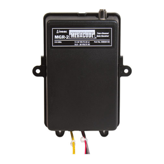
MGR
MGR-2
DIGITAL
GATE
RECEIVER
Installation Instructions
(760) 438-7000
USA & Canada (800) 421-1587 & (800) 392-0123
Toll Free FAX (800) 468-1340
www.linearcorp.com
STEP 1
Connect receiver relay output
Connect the appropriate channel wires (Ch. 1 - two gray wires)., (Ch. 2 - two yellow
wires) to the appropriate activation terminals on the gate operator.
STEP 4
Connect antenna
Connect the coaxial cable to the "F" connector on the receiver. Drill a 3/8" hole on
the top of the operator housing for the bulkhead connector. Insert the connector and
secure it with the nut and lock washer. Connect the cable and antenna to the bulkhead
connector.
CONNECT COAXIAL
CABLE TO "F"
CONNECTOR
Description
The MegaCode series of digital receivers are wireless radio controls
designed for use with automatic gate openers or garage door operators.
The MegaCode radio format provides unparalleled security. The transmitter
and receiver can be programmed to more than a million different codes.
MegaCode receivers and transmitters do not contain a typical "coding switch". Each
transmitter is pre-set at the factory to a unique code. The receiver is programmed
by sending a signal to it from the transmitter(s) that are going to be used with it.
This stores the transmitters code into the receiver's memory. The receiver will
retain its memory even without power. The receiver will activate only from these
"memorized" transmitters. Each MegaCode receiver can remember a maximum
of 40 transmitters.
The receivers can operate from 12-30 volts AC or 10.5-30 volts DC and are normally
powered from the gate operator. The relay contact(s) are rated at 5 amps @ 32 volts
AC/DC NEC Class 2 circuit.
STEP 2
Connect receiver to power
Connect the red power input wire to the radio power and the black wire to the common
terminal on the gate operator.
STEP 5
Open receiver case
To open the receiver case, remove the screws, squeeze sides of case and rotate
upward.
SLIDE WEATHER
RESISTANT CAP
OVER CONNECTION
INSERT BULKHEAD
CONNECTOR THROUGH
OPERATOR HOUSING
SECURE CONNECTOR
TO HOUSING USING
WASHER AND NUT
CONNECT CABLE TO
SQUEEZE BOTH SIDES AT TABS
BULKHEAD CONNECTOR
AND TILT UPWARD
The MGR series has an "F" connector for attaching an antenna. The receiver
is supplied with a 9-inch local antenna, a three foot 75 ohm coaxial cable, and a
bulkhead connector for mounting the antenna outside the gate operator enclosure
RECEIVER
LOCAL
ANTENNA
BULKHEAD
CONNECTOR
STEP 3
Mount the receiver
Use the screws provided to mount the receiver within the operator housing. This
provides protection from the elements. Secure case with case screws.
MOUNT RECEIVER
INSIDE GATE
HOUSING
SECURE CASE
CLOSED WITH TWO
SCREWS AT BOTTOM
OF CASE
STEP 6A MGR & MGR-2 channel one code switch
The pushbutton labeled S1 is used to program transmitters to channel one.
CHANNEL ONE
PUSHBUTTON
S1
S2
S1
USE THIS
PUSHBUTTON
TO ENTER
TRANSMITTERS
INTO CHANNEL
ONE
3-FOOT
CABLE
CASE SCREWS
MOUNTING
HARDWARE
NUT
WASHER
Advertisement
Table of Contents

Related Manuals for Linear MegaCode MGR-2


Summary of Contents for Linear MegaCode MGR-2
- Page 1 Description The MegaCode series of digital receivers are wireless radio controls The MGR series has an “F” connector for attaching an antenna. The receiver designed for use with automatic gate openers or garage door operators. is supplied with a 9-inch local antenna, a three foot 75 ohm coaxial cable, and a MGR-2 The MegaCode radio format provides unparalleled security.
- Page 2 fitness, are valid only until Warranty Expiration ✶ Infrequently used radio links should be tested regularly to protect against Date as labeled on the product. This Linear LLC Warranty is in lieu of all undetected interference or fault.
Need help?
Do you have a question about the MegaCode MGR-2 and is the answer not in the manual?
Questions and answers