Table of Contents
Advertisement
DXR-702
TWO-
CHANNEL
DIGITAL
RECEIVER
Installation
Instructions
(760) 438-7000 • FAX (760) 438-7043
USA & Canada (800) 421-1587 & (800) 392-0123
Toll Free FAX (800) 468-1340
www.linearcorp.com
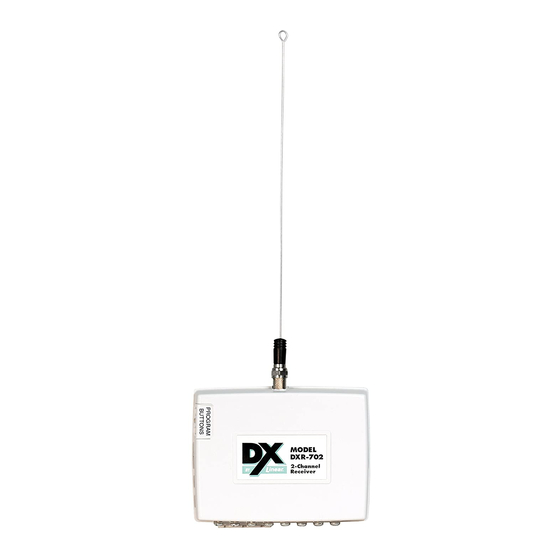
DXR-702 FEATURES
ANTENNA
CONNECTOR
CHANNEL 2
PROGRAM
BUTTON
PROGRAM
INDICATOR
CHANNEL 1
PROGRAM
BUTTON
INSTALLATION TIPS
RIGHT
CENTRALLY LOCATE RECEIVER
TRANSMITTERS AT THE OTHER END OF
OR ANTENNA
HOUSE MIGHT BE TOO FAR AWAY
RCVR
BASEMENT
RIGHT
LOCATING A RECEIVER OR ANTENNA
MOUNT RECEIVER OR ANTENNA AS
HIGH ABOVE EARTH LEVEL AS POSSIBLE
BELOW EARTH LEVEL WILL IMPAIR RANGE
CONSTRUCTION MATERIALS WILL EFFECT RADIO RANGE
90% - 100%
65% - 95%
OF FULL POWER
OF FULL POWER
WALLBOARD AND
LIGHT CONCRETE
WOOD STUDS
OR BRICK
The DXR-702 is a two-channel digital receiver with two isolated
relay outputs designed for use with Linear's DX Format
transmitters. This receiver can be used in a variety of remote
control applications. When the receiver detects a signal from
a transmitter programmed into its memory, the appropriate
relay output activates. The relays have four optional output
BY
configurations. When the relays are set to latch, the receiver
outputs will follow the open/close door status sent from DXT-31
door/window transmitters.
In a typical installation, the receiver is connected to an alarm
control panel, door strike, camera, high current relay or some
other devices. Transmitters are used to activate or control the
devices. The receiver should be mounted with the supplied
mounting bracket indoors or inside a weather resistant
non-metallic housing.
The digital DX code format features over a million possible
codes. The DX transmitters are precoded at the factory to
unique codes, so no field coding is required. For versatility,
any transmitter can be programmed into any receiver channel.
Receivers must be programmed to the transmitter's code before
system testing and operation. Up to 32 transmitters maximum
can be programmed into the receiver. The transmitters can
be split in any number between the two receiver channels.
1
POWER
INPUT
11-17 VDC
12-16 VAC
POWER AND
RELAY
TERMINALS
WRONG!
RCVR
BASEMENT
WRONG!
BRACKET CAN
MOUNT IN THREE
PLACES
10% - 70%
OF FULL POWER
LOCATION 1
CONCRETE WITH STEEL
REINFORCEMENT OR
METAL LATH AND PLASTER
PRODUCT DESCRIPTION
TERMINAL DETAILS
8
7
CHANNEL 2
6
5
RELAY
4
3
NORMALLY
2
CLOSED
COMMON
NORMALLY
OPEN
CHANNEL 1
RELAY
NORMALLY
CLOSED
COMMON
NORMALLY
OPEN
MOUNTING RECEIVER
MOUNTING NOTES:
1. WHEN USING THE LOCAL WHIP
ANTENNA, MOUNT RECEIVER AS HIGH
AS POSSIBLE FOR BEST RADIO RANGE
2. WHEN USING THE LOCAL WHIP
USE SCREWS TO
ANTENNA, KEEP RECEIVER AWAY
FROM METAL OBJECTS THAT CAN
ATTACH THE
DECREASE RADIO RANGE BY
MOUNTING
SHIELDING THE SIGNAL
BRACKET
3. IN ALL INSTALLATIONS, KEEP
RECEIVER AND ANTENNA AWAY FROM
MOTORS, FANS AND OTHER
ELECTRICAL DEVICES THAT MAY
CAUSE INTERFERENCE AND REDUCE
RADIO RANGE
SNAP RECEIVER
ONTO BRACKET
CORNER HOLE IS
SHARED FOR
LOCATIONS 2 & 3
LOCATION 2
LOCATION 3
Receiver channel two is a special channel. If channel two
memory is empty, with no transmitters programmed into it, it
will report low battery signals from any channel one transmitters
capable of sending them. When a low battery transmission is
received, the channel two relay will latch, regardless of how
the option jumpers are set. The relay will remain engaged until
the channel two program button is pressed. The low transmitter
batteries should be replaced before resetting the relay.
The unit can be powered from a 11-17 VDC or 12-16 VAC power
source. The relays' normally open and normally closed contacts
can switch up to 1 amp at 24 volts AC/DC.
Cutting jumpers select how the relays activate. Four settings
are possible. Both relays will function with the same option. The
factory setting causes the relays to engage for four seconds
each activation. Optionally, the relays can be set to engage for
one second, toggle on with one activation then off with the next,
or latch engaged for door status or until reset by pressing the
program button.
A nine-inch wire whip antenna screws into the receiver's antenna
connector. Optionally, a remote antenna (Linear EXA-1000) can
be connected to the receiver for greater radio range. The red
program indicator lights during RF reception. The installer can
verify that signals are being sent from transmitters and diagnose
interference problems by viewing the indicator. The indicator also
lights during memory programming/erasing and flashes to count
the number of transmitters in memory.
CUTTING OPTION JUMPERS
RELAY OPTIONS EFFECT BOTH RELAYS
NOTE:
IF RELAY OPTION IS GOING TO
TERMINALS
BE CHANGED: REMOVE POWER,
CUT JUMPERS, APPLY POWER,
ERASE MEMORY, THEN RE-
PROGRAM ALL TRANSMITTERS
OPEN CASE
WITH SMALL
SCREWDRIVER
ANTENNA
RELAY OPTION
JUMPER WJ1
4 SECOND LATCH
SOLID
1 SECOND LATCH
CUT
LATCH UNTIL RESET ++
SOLID
TOGGLE ON AND OFF ++
CUT
BE SURE POWER IS OFF WHEN CUTTING JUMPERS
++ CAN BE RESET BY PUSHING THE PROGRAM BUTTON ONCE
NOTE:
TO MONITOR DOOR OPEN/CLOSE STATUS WITH DXT-31 TRANSMITTERS,
SET RELAYS TO LATCH
RELAY ON = DOOR OPEN
RELAY OFF = DOOR CLOSED
OTHER TYPES OF TRANSMITTERS WILL LATCH RELAYS ON UNTIL RESET
ANTENNA INSTALLATION
SCREW LOCAL
WHIP ANTENNA
ONTO RECEIVER
- OR -
UP TO 25 FEET
OF RG-59 CABLE
ALLOWED
ANTENNA NOTES:
1. ANTENNA SHOULD BE MOUNTED
AS HIGH AS PRACTICAL.
2. KEEP ANTENNA AWAY FROM
ELECTRICAL INTERFERENCE
SOURCES.
3. CENTRALLY LOCATE ANTENNA
AMONG THE TRANSMITTERS.
JUMPER
WJ1
JUMPER
WJ2
RECEIVER CIRCUIT BOARD
JUMPER WJ2
SOLID
SOLID
CUT
CUT
MODEL
EXA-1000
ANTENNA
USE REMOTE
ANTENNA
Advertisement
Table of Contents

Related Manuals for Linear DXR-702


Summary of Contents for Linear DXR-702
-
Page 1: Installation Instructions
DXR-702 PRODUCT DESCRIPTION The DXR-702 is a two-channel digital receiver with two isolated Receiver channel two is a special channel. If channel two relay outputs designed for use with Linear’s DX Format memory is empty, with no transmitters programmed into it, it transmitters. -
Page 2: Terminal Connections
Warranty Expiration Date as 2. CONTINUE TO HOLD THE labeled on the product. This Linear Corporation Warranty is in lieu of all other BUTTON AFTER THE COUNT warranties express or implied.
Need help?
Do you have a question about the DXR-702 and is the answer not in the manual?
Questions and answers