Advertisement
DXSR-1504
DXSR-1508
SUPERVISED
DIGITAL RECEIVERS
Installation Instructions
(760) 438-7000 • FAX (760) 438-7043
USA & Canada (800) 421-1587 & (800) 392-0123
Toll Free FAX (800) 468-1340
www.linearcorp.com
STATUS
CHANNEL
INDICATORS
DISPLAY
CHANNEL BUTTON
ACCESS PANEL
CASE LOCKING
OPTION JUMPERS AND CHANNEL BUTTONS DETAIL
CHANNEL 3
CHANNEL 1
CHANNEL 4
CHANNEL 2
CHANNEL 7
CHANNEL 6
CHANNEL 5
DXSR-1508 ONLY
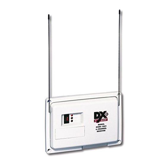
ATTACH ANTENNAS
INSTALL THE TWO
ANTENNAS UNDER THE
LEFT AND RIGHT
ANTENNA TERMINALS
FEATURES
OPEN CASE TO
VIEW COMPONENTS
SCREW
CHANNEL 8
CHANNEL
BUTTON
CHANNEL BUTTONS ARE USED DURING PROGRAMMING AND
TO UNLATCH THE CHANNEL'S OUTPUT IN LATCHED MODE
OUTPUT JUMPERS SELECT MOMENTARY, TOGGLE, OR
LATCHED OUTPUT FOR EACH CHANNEL
WHEN A CHANNEL'S STATUS JUMPER IS CUT, THE CHANNEL
WILL REQUIRE STATUS TRANSMISSIONS FROM A SUPERVISED
TRANSMITTER PROGRAMMED INTO THAT CHANNEL
TIGHTEN ANTENNA TERMINALS WITH
ANTENNA WHIPS BELOW THE SCREW
AND UNDER THE TERMINAL PLATE
AS SHOWN (BE SURE TOP COVER SLOTS
ALIGN WITH ANTENNAS)
The DXSR-1504 and DXSR-1508 are four and eight channel supervised digital receivers with solid state outputs designed
for use with Linear's DX and DXS Format transmitters. These receivers can be used in a variety of security and remote
control applications. When the receiver detects a signal from a transmitter programmed into its memory, the appropriate
channel output activates. The channel outputs have three optional configurations; momentary, toggle on/off, and latch until
restored. Status and low battery outputs are for supervisory indications. Cutting jumpers select which channels require
supervisory status reports from transmitters.
Each unit incorporates a dual high-sensitivity superheterodyne diversity receiver with two whip antennas. This type of
receiver provides superior performance by preventing loss of signal due to multi-path interference.
In a typical installation, the receiver is connected to an alarm control panel, door strike, camera, high current relay or some
other devices. Transmitters are used to activate or control the devices. The receiver should be mounted indoors or inside
a weather resistant non-metallic housing for outdoor use.
The digital DX/DXS code format features over a million possible codes. The transmitters are precoded at the factory to
unique codes, so no field coding is required. For versatility, any transmitter can be programmed into any receiver channel.
Receivers must be programmed to recognize the transmitter's code before system testing and operation. Up to 32
transmitters can be programmed into the receiver. Each button on multi-button portable transmitters send a unique code,
and are programmed as separate transmitters.
The CHANNEL display shows the channels activated and the presence of radio activity. Individual indicators for ALARM,
STATUS, and LOW BATT show the supervisory status of each receiver channel. All outputs can be configured for normally
open or normally closed.
The units can be powered from a 10.2-14.4 VDC or 12-16 VAC power source. The units will draw about 35 mA standby
and up to 120 mA in alarm.
LEFT ANTENNA
TERMINAL
RADIO ACTIVITY
INDICATOR
CHANNEL
BUTTONS
OUTPUT
JUMPERS
STATUS
JUMPERS
MOUNT RECEIVER AS HIGH
AS PRACTICAL USING
THE SCREWS AND SCREW
ANCHORS PROVIDED
STATUS
JUMPER
OUTPUT
JUMPER
SECURE WIRES WITH ZIP-TIE
FROM POWER SOURCE
10.2-14.4 VDC OR 12-16 VAC
120 mA MINIMUM
NOTE: SEE WIRING EXAMPLES ON
REVERSE SIDE OF THESE INSTRUCTIONS
PRODUCT DESCRIPTION
COMPONENT LOCATIONS
STATUS
CHANNEL
INDICATOR
DISPLAY
LOW BATTERY
ALARM
INDICATOR
INDICATOR
RECESSED WIRING
WIRING STRAIN
ACCESS HOLE
RELIEF POSTS
MOUNT RECEIVER
COVER THE SCREWS WITH THE
FOUR SCREW HOLE PLUGS PROVIDED
CONNECT TERMINALS
OUTPUTS TO DEVICE TO BE TRIGGERED
RIGHT ANTENNA
TERMINAL
AUDIO TEST
POINT
GROUND
TEST POINT
OUTPUT POLARITY
JUMPER
PROGRAM
JUMPER
TERMINAL
BLOCK
MODEL DXSR-1508 ONLY
100 mA MAXIMUM PER OUTPUT
WITH OUTPUT POLARITY JUMPER IN
PLACE, ALL OUTPUTS WILL SWITCH
TO GROUND WHEN ACTIVE
Advertisement

Subscribe to Our Youtube Channel
Related Manuals for Linear DXSR-1504


Summary of Contents for Linear DXSR-1504
-
Page 1: Installation Instructions
The DXSR-1504 and DXSR-1508 are four and eight channel supervised digital receivers with solid state outputs designed for use with Linear’s DX and DXS Format transmitters. These receivers can be used in a variety of security and remote control applications. When the receiver detects a signal from a transmitter programmed into its memory, the appropriate channel output activates. -
Page 2: Wiring Examples
Linear does not warrant this product to consumers. Consumers should inquire from their selling dealer as to the nature of the dealer’s warranty, if any. There are no obligations or liabilities on the part of Linear corporation for consequential damages arising out of or in connection with use or performance of this product or other indirect damages with respect to loss of property, revenue, or profit, or cost of removal, installation, or reinstallation.
Need help?
Do you have a question about the DXSR-1504 and is the answer not in the manual?
Questions and answers