
Related Manuals for Check Point 61000


Summary of Contents for Check Point 61000
- Page 1 30 April 2018 CHECK POINT 61000 SECURITY SYSTEM R75.40VS FOR 61000 Getting Started Guide...
- Page 2 Check Point. While every precaution has been taken in the preparation of this book, Check Point assumes no responsibility for errors or omissions. This publication and features described herein are subject to change without notice.
-
Page 3: Important Information
Latest Documentation The latest version of this document is at: http://supportcontent.checkpoint.com/documentation_download?ID=20444 To learn more, visit the Check Point Support Center http://supportcenter.checkpoint.com. For more about this release, see the R75.40VS for 61000 home page https://supportcenter.checkpoint.com/supportcenter/portal?eventSubmit_doGoviewsolutiondetail s=&solutionid=sk89900. Revision History Date... - Page 4 Feedback Check Point is engaged in a continuous effort to improve its documentation. Please help us by sending your comments mailto:cp_techpub_feedback@checkpoint.com?subject=Feedback on R75.40VS Check Point 61000 Security System Getting Started Guide.
-
Page 5: Table Of Contents
Health and Safety Information ..................7 Informations relatives à la santé et à la sécurité ............9 Introduction ......................... 12 Overview of Check Point 61000 Security Systems ........... 12 Check Point Virtual Systems ................... 13 In this Document ..................... 14 Shipping Carton Contents .................. - Page 6 Installing the SGM Image ..................55 Installing the SGM with Snapshot Import ..............55 Installing the SGM Image from Removable Media ............55 Step 7: Connecting to the Network ................58 Step 8: Initial Software Configuration ................. 59 Connecting a Console ....................59 Running the Initial Setup ..................
-
Page 7: Health And Safety Information
Division 4.5, Chapter 33. Best Management Practices for Perchlorate Materials. This product, part, or both may include a lithium manganese dioxide battery, which contains a perchlorate substance. Proposition 65 Chemical Check Point 61000 Security System Getting Started Guide R75.40VS for 61000... - Page 8 This product is in conformity with Low Voltage Directive 2006/95/EC, and complies with the requirements in the Council Directive 2006/95/EC relating to electrical equipment designed for use within certain voltage limits and the Amendment Directive 93/68/EEC. Check Point 61000 Security System Getting Started Guide R75.40VS for 61000...
-
Page 9: Informations Relatives À La Santé Et À La Sécurité
Ne tenez la carte que par ses bords. Ne touchez aucun composant, puce périphérique, module mémoire ou contact plaqué or. • Lorsque vous manipulez des modules mémoire, ne touchez pas leurs broches ou les pistes de contact dorées. Check Point 61000 Security System Getting Started Guide R75.40VS for 61000... - Page 10 Information à l'intention de l'utilisateur : Le manuel utilisateur ou le manuel d'instruction d'un dispositif rayonnant (intentionnel ou non) doit avertir que toute modification non approuvée expressément par la partie responsable de la Check Point 61000 Security System Getting Started Guide R75.40VS for 61000...
- Page 11 Pour obtenir plus d'informations sur les lieux où déposer vos équipements mis au rebut, veuillez contacter votre municipalité ou le service de gestion des déchets. Check Point 61000 Security System Getting Started Guide R75.40VS for 61000...
-
Page 12: Introduction
Shipping Carton Contents .................... Thank you for choosing the Check Point 61000 Security System. We hope that you will be satisfied with this system and our support services. Check Point products supply your business with the most up to date and secure solutions available today. -
Page 13: Check Point Virtual Systems
• Lets you install different numbers of SGMs to match the processing needs of your network. You can operate the 61000 Security System as a Security Gateway or as a VSX Gateway for Check Point Virtual Systems. Check Point Virtual Systems Administrators can replicate physical security gateways with Virtual Systems with advanced protection for many networks and network segments. -
Page 14: In This Document
A brief overview of necessary 61000 Security System concepts and features • A step by step guide to getting the 61000 Security System up and running Note - Many examples in this guide show the largest model available at the time of publication. - Page 15 QSFP transceiver for 40GbE ports (SR/LR) • QSFP splitter for 40GbE ports Management and log • Fiber/Twisted pair transceiver for 1GbE SFP+ ports (SX/LX) • SFP+ (10GbE) Fiber transceiver for SFP+ ports (SR/LR) Check Point 61000 Security System Getting Started Guide R75.40VS for 61000...
-
Page 16: Hardware Components
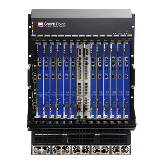
........................Chassis Management Modules ..................Blank Filler Panels for Airflow Management ............. This section shows the hardware components of the 61000 Security System. 61000 Security System Front Panel Modules Check Point 61000 Security System Getting Started Guide R75.40VS for 61000... - Page 17 The Chassis Management Module (CMM) monitors the status of the chassis hardware components. It also supplies DC current to the cooling fan trays. If the Chassis Management Module fails or is removed from the chassis, the 61000 Security System continues to forward traffic. However, hardware monitoring is not available.
-
Page 18: Security Switch Module
Security Gateway Modules. Two are inserted in a Chassis. Two SSM versions are available: • SSM60 • Not supported in a VSX Gateway • SSM160 Check Point 61000 Security System Getting Started Guide R75.40VS for 61000... -
Page 19: Ssm160 Security Switch Module
... eth2-07 • In SmartDashboard, define used interfaces as internal or external. • 1 synchronization port for connecting to and synchronizing with another 61000 appliance that functions as a high availability peer. • 10 GbE SFP+ port •... - Page 20 Security Management Server or dedicated logging servers should be accessible from these interfaces. • 2 x 1GbE SFP port • In the 61000 appliance initial setup program, these interface are labeled • On the left SSM: eth1-Mgmt3, eth1-Mgmt4 • On the right SSM: eth2-Mgmt3, eth2-Mgmt4...
-
Page 21: Ssm60 Security Switch Module
In the initial setup program, the interfaces are named: • On Left SSM: eth1-Mgmt1, eth1-Mgmt2, ... eth1-Mgmt4 • On the right SSM: eth2-Mgmt1, eth2-Mgmt2, ... eth2-Mgmt4 Check Point 61000 Security System Getting Started Guide R75.40VS for 61000... -
Page 22: Security Switch Module Leds
Do not remove SSM is Active. Do not (Normal) remove SYN ACT On (Normal) Normal operation Link Link enabled Yellow Link is active blinking Link is disabled Check Point 61000 Security System Getting Started Guide R75.40VS for 61000... -
Page 23: Security Gateway Module (Sgm)
Blue blinking SGM is going to Standby Mode. Do not remove. Off (Normal) SGM is active. Do not remove. CTRL SSM1 and Yellow Link enabled. Link 1 SSM2 management CTRL Check Point 61000 Security System Getting Started Guide R75.40VS for 61000... - Page 24 Data and Sync traffic in SSM1, SSM2, SS3, SSM4. Not used. Red. Lower Installation Right started. Red blinking, Installation in in sequence progress. Red. All Installation failure. Yellow. Left Installation completed. Check Point 61000 Security System Getting Started Guide R75.40VS for 61000...
- Page 25 Hardware Components Green. Right SGM is being configured. (Using First Time Configuration Wizard or adding a new SGM into a Chassis). SGM is configured and ready. Check Point 61000 Security System Getting Started Guide R75.40VS for 61000...
-
Page 26: Sgm220 Leds
LEDs 2 and 4 SGM is being configured. - Green (Using First Time Wizard or adding a new SGM into a Chassis) All LEDs - Off SGM is configured and ready Check Point 61000 Security System Getting Started Guide R75.40VS for 61000... -
Page 27: Ac Power Supply Units (Psus)
Red: DC power failure or Hot swap ready Extraction handle for holding the PSU during extraction and insertion Power Requirements: Each PSU supplies power at these values: 1500W at 220VAC 1200W at 110VAC Check Point 61000 Security System Getting Started Guide R75.40VS for 61000... - Page 28 Important - One power supply cannot supply a fully loaded Chassis. This table shows how to calculate the recommended number of power supplies. For a PSU that supplies 1500W Number of SGMs Minimum (N) Recommended (N+1) Check Point 61000 Security System Getting Started Guide R75.40VS for 61000...
-
Page 29: Ac Power Cords
0.75mm2 KC-039, KC-003H, 10 A H05RR-F 3G 13A 250V~ 250V~ 0.75mm2 KC-001, KC-003H, 15A VCTF 3G 15A 125V 125V 2.0mm2 KC-001, KC-003H, 15A SJT 14/3C 15A 125V 125V 75ºC Check Point 61000 Security System Getting Started Guide R75.40VS for 61000... - Page 30 Hardware Components Region PLUG CONNECTOR CABLE CHINA KC-017N, KC-003H, 10 A H05RR-F 3G 10A 250V~ 250V~ 0.7mm2 Check Point 61000 Security System Getting Started Guide R75.40VS for 61000...
-
Page 31: Dc Power Entry Modules (Pems)
Hardware Components DC Power Entry Modules (PEMs) The 61000 Security System DC configuration includes two Power Entry Modules (PEMs), each with a rating of -48/-60VDC 125A. The PEMs supply DC power, EMC filtering and over-current protection for the Chassis. Each PEM can supply 100% of Chassis power. The PEM is a customer replaceable unit. - Page 32 Before replacing a PEM, verify that power source is disconnected and isolated. The PEM circuit breaker has only one pole and only disconnects the -48V lead. The 48VDC RTN lead is always connected. Check Point 61000 Security System Getting Started Guide R75.40VS for 61000...
-
Page 33: Fan Trays
Chassis components. Air flows from the inside to the outside of the Chassis. Item Description Power fault LED Locking captive screw Three fan trays are preinstalled (6 fans). Check Point 61000 Security System Getting Started Guide R75.40VS for 61000... -
Page 34: Chassis Management Modules
HS (hot swap) Steady blue Chassis Management Module is powering up or ready for extraction. Blue blink Chassis Management Module is being hot swapped Chassis Management Module in operation Check Point 61000 Security System Getting Started Guide R75.40VS for 61000... - Page 35 Hardware Components Telco Alarm LEDs Status Meaning CRT (Critical) Normal operation System alarm event MJR (Major) Normal operation System Alarm event MNR (Minor) Normal operation System alarm event Check Point 61000 Security System Getting Started Guide R75.40VS for 61000...
-
Page 36: Blank Filler Panels For Airflow Management
Two types of airflow-management panels are available for the empty slots on the Chassis: • Front blank panels with air baffles • Rear panel with air baffles Front Blank Panels with Air Baffles Item Description Slot cover Tightening screws Air Baffles Check Point 61000 Security System Getting Started Guide R75.40VS for 61000... -
Page 37: Step 1: Site Preparation
..................Required Tools ......................Rack Mounting Requirements Before mounting the 61000 Security System in a standard 19" rack, make sure that: • The rack is stable, level, and secured to the building. • The rack is sufficiently strong to support the weight of a fully loaded Security System (https://www.checkpoint.com/downloads/product-related/datasheets/DS-41000-61000.pdf). -
Page 38: Step 2: Installing The Chassis In A Rack
5. Secure the appliance by fastening the mounting screws to the rack. The appliance must be level, and not positioned at an angle. 6. Attach grounding cables to the grounding screws on the Chassis. Check Point 61000 Security System Getting Started Guide R75.40VS for 61000... -
Page 39: Step 3: Installing Hardware Components And Connecting Power Cables
Transceivers into the management ports on the Security Switch Modules • Covers for blank slots This section also covers: • Backup Chassis in a dual Chassis environment • Power cables Check Point 61000 Security System Getting Started Guide R75.40VS for 61000... -
Page 40: Inserting Ac Power Supply Units
1. Pull out the latch. 2. Push in the Power Supply until it locks in place. 3. Push in the Power Supply insertion latch. 4. Make sure that the DC LED show green. Check Point 61000 Security System Getting Started Guide R75.40VS for 61000... -
Page 41: Inserting Fan Trays
Fans are pre-installed in the appliance. Manual replacement must be coordinated with Check Point Support. To Insert a Fan: 1. Slide the fan into the allocated space. 2. Tighten the locking captive screw. Check Point 61000 Security System Getting Started Guide R75.40VS for 61000... -
Page 42: Inserting Chassis Management Modules
5. Tighten the two thumb screws. 6. After power up, all LEDs must light up for 1-2 seconds. The ACT and PWR LEDs continue to show green after the other LEDs turn off. Check Point 61000 Security System Getting Started Guide R75.40VS for 61000... -
Page 43: Inserting Security Switch Modules
1. Open the latches at the top and bottom of the Security Switch Module. 2. Slide the SSM into the allocated slot. 3. Fasten the latches. 4. Tighten the screws. Check Point 61000 Security System Getting Started Guide R75.40VS for 61000... -
Page 44: Inserting Security Gateway Modules
2. Make sure the SGM is located correctly on the Chassis rail. 3. Slide the Security Gateway Module into the allocated slot. 4. Fasten the latches. 5. Tighten the thumb screws. Check Point 61000 Security System Getting Started Guide R75.40VS for 61000... -
Page 45: Inserting Transceivers
Step 3: Installing Hardware Components and Connecting Power Cables Inserting Transceivers For connecting different interface types to the 61000 Security System using SFP, SFP+, or XFP ports on the SSM, Security Switch Modules support Twisted Pair and Fiber Optic transceivers. -
Page 46: Inserting Twisted Pair Transceivers
Twisted pair transceivers can be inserted into: • Data and management ports on the SSM160 • SFP management ports on the SSM60 Slide the transceiver into the open Security Switch Module port. Check Point 61000 Security System Getting Started Guide R75.40VS for 61000... -
Page 47: Inserting Fiber Optic Transceivers
1. Insert the QSFP transceiver into the Security Switch Module. 2. Insert the QSFP splitter cable into the transceiver. This converts the 40GbE QSPF port to 4 x 10GbE ports. Check Point 61000 Security System Getting Started Guide R75.40VS for 61000... -
Page 48: Inserting Front Blank Panels
Note - Rear blank panels are preinstalled on the Chassis. Connecting DC Power Connect the DC PEMs in the 61000 Security System to an external battery power source. You must have a mains DC power supply system that includes batteries and a branch circuit breaker of 125A for each PEM. - Page 49 Set all the circuit breakers to ON. 9. Do step 2 to step 8 for the second PEM. 10. Set the branch circuit breakers at the mains to ON. Check Point 61000 Security System Getting Started Guide R75.40VS for 61000...
-
Page 50: Connecting A Second Chassis
Chassis1 to eth1-Sync in Chassis2 • eth2-Sync in Chassis1 to eth2-Sync in Chassis2 4. Make sure to attach the RX cable to the RX ports and the TX cable to the TX ports. Check Point 61000 Security System Getting Started Guide R75.40VS for 61000... -
Page 51: Step 4: Turning On The System
2. Shutdown the SSMs and CMMs by releasing the levers. 3. After the LEDs on SGMs, SSMs and CMMs (both Chassis) show a steady blue, unplug the power cords. Check Point 61000 Security System Getting Started Guide R75.40VS for 61000... -
Page 52: Step 5: Dual Chassis System Validation
Note - When you add a new CMM to a Chassis, you must validate the Chassis ID. Make sure that the Chassis is in the Standby mode when you do this. Check Point 61000 Security System Getting Started Guide R75.40VS for 61000... -
Page 53: Step 6: Installing The Software
2. If you have a dual Chassis environment, connect one Sync cable between both Chassis: • Connect eth1-Sync on chassis1 to eth1-Sync on chassis2. 3. For IP management of the 61000 Security System, connect a cable to one of the management interfaces on chassis1: •... - Page 54 Initial Policy state. SCP password for SSM160 firmware installation Contact Check Point Support https://www.checkpoint.com/support-services/contact-support/. All firmware installations should be performed with the assistance of the Check Point Support. Check Point 61000 Security System Getting Started Guide R75.40VS for 61000...
-
Page 55: Installing The Sgm Image
Burn the ISO file to a DVD. • Download the Check Point ISOmorphic utility to create a bootable USB device from the ISO. See sk65205 http://supportcontent.checkpoint.com/solutions?id=sk65205. Make sure that your USB device is compatible with ISOmorphic. See sk92423 for details. - Page 56 Enter. There is no time limit for the subsequent steps. 7. Press OK to continue with the installation. After the installation, the 61000 Security System begins the boot process and status messages show in the terminal emulation program.
- Page 57 Connect to the console. Reboot the SGM. Partially remove the SGM and then push it back in place. Select Install Gaia on the system and press Enter. Check Point 61000 Security System Getting Started Guide R75.40VS for 61000...
-
Page 58: Step 7: Connecting To The Network
2. Connect the management ports on the Security Switch Modules to your network. 3. Connect the data ports on the Security Switch Modules to your network. For more information, see the front panel of your appliance ("Hardware Components" on page 16). Check Point 61000 Security System Getting Started Guide R75.40VS for 61000... -
Page 59: Step 8: Initial Software Configuration
Connecting a Console 1. Connect the RJ-45 jack end of a serial cable to the console port on the left-most 61000 Security System in the Chassis. 2. Connect the other end of the serial cable to the computer that you will use to do the initial configuration of the 61000 Security System. -
Page 60: Running The Initial Setup
To associate data port names with the physical ports, refer to ("Security Switch Module" on page 18). For each data port configure: An IP address The net mask length Check Point 61000 Security System Getting Started Guide R75.40VS for 61000... - Page 61 Step 8: Initial Software Configuration 8. Configure Routing. Note - Wait 10-20 seconds for routing information to be updated throughout the system. 9. The Welcome to Check Point Suite screen shows. Wait for Check Point products packages to install. 10. Wait for the: •...
-
Page 62: Step 9: Smartdashboard Configuration
Configuring a VSX Gateway ..................The 61000 Security System can work as a Security Gateway or as a VSX Gateway. The Security Management Server must be NGX R65 or higher. Important - R76 SmartDashboard is not supported. You must download and install the updated SmartDashboard as instructed. -
Page 63: Confirming The Security Gateway Software Configuration
Step 9: SmartDashboard Configuration 11. Click Finish. The General Properties page of the 61000 Security System object opens. 12. In the General Properties page, make sure the Version is correct. 13. Enable the Firewall Software Blade. Enable other supported Software Blades as necessary. -
Page 64: Configuring A Vsx Gateway
Step 9: SmartDashboard Configuration Configuring a VSX Gateway The 61000 Security System can work as a Security Gateway or as a VSX Gateway. This procedure shows how to configure a VSX Gateway in SmartDashboard. Before creating the VSX Gateway Understand how VSX works, and the VSX architecture and concepts. Also, you should understand how to deploy and configure your security environment using the VSX Virtual Devices: •... -
Page 65: Wizard Step 1: Defining Vsx Gateway General Properties
In the VSX Gateway Interfaces window, define physical interfaces as VLAN trunks. The window shows the interfaces currently defined on the VSX Gateway. To define an interface as a VLAN trunk, select VLAN Trunk for the interface. Check Point 61000 Security System Getting Started Guide R75.40VS for 61000... -
Page 66: Virtual Network Device Configuration
4. Define the IP address and Net Mask for a Virtual Router. These options are not available for a Virtual Switch. 5. Optional: Define a Default Gateway for a Virtual Router (DMI only). Check Point 61000 Security System Getting Started Guide R75.40VS for 61000... -
Page 67: Wizard Step 6: Vsx Gateway Management
1. Connect to the appliance with an SSH client or the serial console. 2. Run: # asg monitor -vs all 3. Make sure that the status for SGMs is Enforcing Security on the Active and Standby Chassis, for all Virtual Systems. Check Point 61000 Security System Getting Started Guide R75.40VS for 61000... - Page 68 4. You can now add more SGMs to the Security Group. Run: # asg security_group 5. After all SGMs are UP and enforcing Security, you can add Virtual Systems to the VSX Gateway. Check Point 61000 Security System Getting Started Guide R75.40VS for 61000...
-
Page 69: Basic Configuration Using Gclish
Routes Applicable Modes Set a default route Security Gateway # set static-route default nexthop gateway address 192.0.20.1 on Show the route table Security Gateway # show route VSX Gateway Check Point 61000 Security System Getting Started Guide R75.40VS for 61000... - Page 70 VSX Gateway Revert to a snapshot Security Gateway # set snapshot revert <snapshot name> VSX Gateway Show snapshots and Security Gateway # show snapshots monitor snapshot VSX Gateway progress Check Point 61000 Security System Getting Started Guide R75.40VS for 61000...
-
Page 71: Licensing And Registration
3. Generate a license based on the IP address of the SSM interface connected to your Security Management Server. Note - Because the 61000 Security System has a single Management IP address, in dual chassis environments, the Active and Standby chassis should be bound to the same IP address same in the license. -
Page 72: Monitoring And Configuration
- Shows all Virtual Systems. Note: This parameter is only relevant in a VSX environment. For a Chassis with more than 3 SGMs, the output uses abbreviations to make the output more compact. Check Point 61000 Security System Getting Started Guide R75.40VS for 61000... -
Page 73: Monitoring Chassis And Component Status (Asg Monitor)
For a Chassis with more than 3 SGMs, the output has abbreviations to make the output more compact. Shows legend of column title abbreviations. Shows the command syntax and help information. Check Point 61000 Security System Getting Started Guide R75.40VS for 61000... - Page 74 | Minimum grade gap for chassis failover: | Synchronization Within chassis: Enabled (Default) Between chassis: Enabled (Default) Exception Rules: (Default) ----------------------------------------------------------------------------- | Chassis HA mode: Primary Up (Chassis 1) ----------------------------------------------------------------------------- Check Point 61000 Security System Getting Started Guide R75.40VS for 61000...
-
Page 75: Monitoring Performance Indicators And Statistics (Asg Perf)
Note: In a VSX Gateway, if no –vs option is specified , the command runs in the context of the current VS. Verbose mode: Per-SGM display. Show performance statistics (including load and acceleration load) on the Active Chassis. Check Point 61000 Security System Getting Started Guide R75.40VS for 61000... - Page 76 Display usage. Example If no SGMs are specified, the command shows performance statistics for the Active Chassis: > asg perf -v Output Notes: Load Average = CPU load. Check Point 61000 Security System Getting Started Guide R75.40VS for 61000...
-
Page 77: Monitoring Hardware Components (Asg Hw_Monitor)
| CPUtemp | blade 8, CPU1 | 65 | Celsius | CPUtemp | blade 9, CPU0 | 65 | Celsius | CPUtemp | blade 9, CPU1 | 65 | Celsius Check Point 61000 Security System Getting Started Guide R75.40VS for 61000... - Page 78 | Speed Level | 1 | Fan | bay 2, fan 2 | 11 | Speed Level | 1 | Fan | bay 3, fan 1 | 11 | Speed Level | 1 Check Point 61000 Security System Getting Started Guide R75.40VS for 61000...
- Page 79 | PowerConsumption | N/A | 1894 | 4050 | Watts | PowerUnit(AC) | bay 1 | NA | PowerUnit(AC) | bay 2 | NA | PowerUnit(AC) | bay 3 | NA Check Point 61000 Security System Getting Started Guide R75.40VS for 61000...
- Page 80 | bay 3, fan 1 | NA | PowerUnitFan | bay 3, fan 2 | NA | SSM | bay 1 | Mbps | SSM | bay 2 | Mbps ------------------------------------------------------------------------------ Check Point 61000 Security System Getting Started Guide R75.40VS for 61000...
-
Page 81: Monitoring Sgm Resources (Asg Resource)
0 = Component not installed State 1 = Component is installed Monitoring SGM Resources (asg resource) Use this command to show SGM resource usage and thresholds for the entire 61000 Security System. Syntax > asg resource [-b <sgm_ids>] > asg resource -h... - Page 82 For example, the first row shows that SGM1 on Chassis 1 has 31.3 GB of memory, 31% of which is used. An alert is sent if the usage is greater than 50%. Check Point 61000 Security System Getting Started Guide R75.40VS for 61000...
-
Page 83: Searching For A Connection (Asg Search)
<10.33.86.2, 49600, 194.29.36.43, 8080, tcp> -> [1_01 A, 1_07 B, 2_01 B] <10.33.86.2, 49601, 194.29.36.43, 8080, tcp> -> [1_01 A, 1_07 B, 2_01 B] Legend: A - Active SGM B - Backup SGM Check Point 61000 Security System Getting Started Guide R75.40VS for 61000... - Page 84 Searching for tcp connection with source IP address 10.33.86.2 and destination port 8080. The output shows three connections handled on SGM 1_01 with a backup on SGM 1_07 and 2_01. Check Point 61000 Security System Getting Started Guide R75.40VS for 61000...
-
Page 85: Configuring Alerts For Sgm And Chassis Events (Asg Alert)
Sender email address - Sender email address for email alerts. • Subject - Subject header text for the email alert. • Body text - User-defined text for the alert message. Check Point 61000 Security System Getting Started Guide R75.40VS for 61000... - Page 86 | Hard Drive Utilization | Memory Utilization Alert Modes • Enabled - An alert is sent for the selected events. • Disabled - No alert is sent for the selected events. Check Point 61000 Security System Getting Started Guide R75.40VS for 61000...
- Page 87 Monitoring and Configuration Monitor - A log entry is generated instead of an alert. • Check Point 61000 Security System Getting Started Guide R75.40VS for 61000...
-
Page 88: Monitoring The System With Snmp
Monitoring and Configuration Monitoring the System with SNMP You can use SNMP to monitor different aspects of the 61000 Security System, including: • Software versions • Hardware status • Key performance indicators • Chassis high availability status To monitor the system using SNMP: 1. -
Page 89: Snmp In A Vsx Gateway
To run a Virtual System query for traffic throughput, from its virtual context: 1. Go to the Expert mode. 2. Go to the applicable Virtual System: vsenv <vs_id> 3. Run: # snmpwalk -m $CPDIR/lib/snmp/chkpnt.mib -v 2c -c public localhost asgThroughput Check Point 61000 Security System Getting Started Guide R75.40VS for 61000... -
Page 90: Troubleshooting
[Number of logs to keep] The number of the newest logs to keep when deleting (purging) asg diag log files. The default is 5. Example 1 asg diag list Check Point 61000 Security System Getting Started Guide R75.40VS for 61000... - Page 91 The output shows that the Test with ID 1 is called System Health. This test runs the command asg stat –d to get the test status. Example 2 asg diag verify Check Point 61000 Security System Getting Started Guide R75.40VS for 61000...
- Page 92 | asg resource -q 4 | Software Versions | asg_version verify -v 5 | CPU Type | cpu_socket_verifier -v ------------------------------------------------------- | Networking ------------------------------------------------------- | 24 | Dynamic Routing | asg_dr_verifier ------------------------------------------------------- Check Point 61000 Security System Getting Started Guide R75.40VS for 61000...
- Page 93 A sample full (verbose) output for the CPU Type test in the /var/log/ log file: ============================== Output 2.3 CPU Type: ============================== Non-compliant cpu models found: ------------------------------------ model name : Intel(R) Xeon(R) CPU E5530 @ 2.40GHz Refer to /proc/cpuinfo for more information Check Point 61000 Security System Getting Started Guide R75.40VS for 61000...
- Page 94 | Passed | -------------------------------------------------------------------------------- | Networking -------------------------------------------------------------------------------- | 24 | Dynamic Routing | Passed | -------------------------------------------------------------------------------- | Tests Summary -------------------------------------------------------------------------------- | Passed: 6/6 tests | Output file: /var/log/verifier_sum.1-5.24.2012-11-28_10-37-36.txt -------------------------------------------------------------------------------- Check Point 61000 Security System Getting Started Guide R75.40VS for 61000...
-
Page 95: Error Types
Disk capacity in GB for the /boot partition. HD: /boot The maximum permissible clock difference, in seconds, between the SGMs Skew and SSMs. Certified cpu Each line represents one compliant CPU type. Check Point 61000 Security System Getting Started Guide R75.40VS for 61000...
Need help?
Do you have a question about the 61000 and is the answer not in the manual?
Questions and answers