Table of Contents
Advertisement
Quick Links
Download this manual
See also:
Getting Started Manual
Advertisement
Table of Contents

Related Manuals for Check Point 61000


Summary of Contents for Check Point 61000
-
Page 1: Security System
Check Point 61000 Security System R75.40VS for 61000 Getting Started Guide 23 January 2014 Protected... - Page 2 Check Point. While every precaution has been taken in the preparation of this book, Check Point assumes no responsibility for errors or omissions. This publication and features described herein are subject to change without notice.
-
Page 3: Important Information
Latest Documentation The latest version of this document is at: (http://supportcontent.checkpoint.com/documentation_download?ID=20444) To learn more, visit the Check Point Support Center (http://supportcenter.checkpoint.com). For more about this release, see the R75.40VS for 61000 home page (https://supportcenter.checkpoint.com/supportcenter/portal?eventSubmit_doGoviewsolutiondetails=&solutio nid=sk89900). Revision History Date... -
Page 4: Health And Safety Information
Handling the cord on this product will expose you to lead, a chemical known to the State of California to cause cancer, and birth defects or other reproductive harm. Wash hands after handling. Check Point Chassis Security System Getting Started Guide R75.40VS for 61000 | 4... - Page 5 For more information about where you can drop off your waste equipment for recycling, please contact your local city office or your household waste disposal service. Check Point Chassis Security System Getting Started Guide R75.40VS for 61000 | 5...
-
Page 6: Informations Relatives À La Santé Et À La Sécurité
Drinking Water and Toxic Enforcement Act of 1986 du California Health & Safety Code s. 25249.5, et seq. (« Proposition 65 »), qui sont « connus par l'état pour causer le cancer ou être toxiques pour la reproduction » (voir http://www.calepa.ca.gov) Check Point Chassis Security System Getting Started Guide R75.40VS for 61000 | 6... - Page 7 Il est de votre responsabilité de le porter à un centre de collecte désigné pour le recyclage des équipements électriques et électroniques. Le fait de séparer vos équipements lors de Check Point Chassis Security System Getting Started Guide R75.40VS for 61000 | 7...
- Page 8 Pour obtenir plus d'informations sur les lieux où déposer vos équipements mis au rebut, veuillez contacter votre municipalité ou le service de gestion des déchets. Check Point Chassis Security System Getting Started Guide R75.40VS for 61000 | 8...
-
Page 9: Table Of Contents
Connecting AC Power Cables ................... 39 Connecting DC Power ....................... 39 Connecting a Second Chassis ................... 41 Step 4: Turning on the 61000 Security System ..............42 Step 5: Validating Chassis ID on a Dual Chassis Configuration ........43 Step 6: Software Installation ....................44 Before Installing Firmware and Software ................ - Page 10 Step 8: Initial Software Configuration ................50 Connecting a Console ....................... 50 Working on the Initial Setup ....................50 Step 9: SmartDashboard Configuration ................53 Configuring a Security Gateway ..................53 Confirming the Security Gateway Software Configuration ..........54 Configuring a VSX Gateway ....................54 Wizard Step 1: Defining VSX Gateway General Properties ...........
-
Page 11: Introduction
Lets you install different numbers of SGMs to match the processing needs of your network. You can operate the 61000 Security System as a Security Gateway or as a VSX Gateway for Check Point Virtual Systems. Check Point Virtual Systems... - Page 12 Up to 250 fully independent Virtual Systems can be supported on the 61000 Security System, delivering scalability, availability and performance while dramatically reduce hardware investment, space requirements and maintenance costs. The latest Check Point technologies ensure the best performance for virtualized security;...
-
Page 13: In This Document
A brief overview of necessary 61000 Security System concepts and features A step by step guide to getting the 61000 Security System up and running Note - Screen shots in this guide may apply only to the highest model to which this guide applies. -
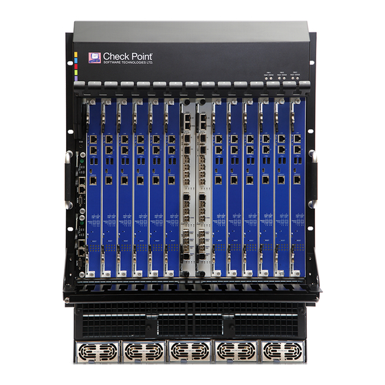
Page 14: Hardware Components
Security Gateway Module slots are numbered 1 to 12, left to right. Slot 7 for example, (labeled [7] in the diagram) is the slot that is immediately to the right of the two Security Switch Module slots. Check Point Chassis Security System Getting Started Guide R75.40VS for 61000 | 14... - Page 15 The Chassis Management Module (CMM) monitors the status of the chassis hardware components. It also supplies the DC current to the cooling fan trays. If the Chassis Management Module fails or is removed from the chassis, the 61000 Security System continues to forward traffic. However, hardware monitoring is not available. Adding or removing a Security Gateway Module to or from the chassis is not recognized.
-
Page 16: Security Switch Module (Ssm)
Security Gateway Modules. Two are inserted in a chassis. Two SSM versions are available: SSM60 Not supported in a VSX Gateway Not supported for SGM240 SSM160 Check Point Chassis Security System Getting Started Guide R75.40VS for 61000 | 16... -
Page 17: Ssm160 Security Switch Module
In the 61000 appliance initial setup program, these interfaces are labeled: On the left SSM: eth1-Mgmt1, eth1-Mgmt2 On the right SSM: eth2-Mgmt1, eth2- Mgmt2 Check Point Chassis Security System Getting Started Guide R75.40VS for 61000 | 17... -
Page 18: Ssm60 Security Switch Module
In the initial setup program, the interfaces are named: On Left SSM: eth1-Mgmt1, eth1-Mgmt2, ... eth1-Mgmt4 On the right SSM: eth2-Mgmt1, eth2-Mgmt2, ... eth2-Mgmt4 Check Point Chassis Security System Getting Started Guide R75.40VS for 61000 | 18... -
Page 19: Security Switch Module Leds
Do not remove Off (Normal) SSM is Active. Do not remove SYN ACT On (Normal) Normal operation Link Link enabled Yellow Link is active blinking Link is disabled Check Point Chassis Security System Getting Started Guide R75.40VS for 61000 | 19... -
Page 20: Security Gateway Module (Sgm)
Link 2 Yellow Link is active blinking Link is disabled CTRL SSM1 and Yellow 10 Gbps SPEED SSM2 management Green 1 Gbps ports CTRL 100 Mbps Check Point Chassis Security System Getting Started Guide R75.40VS for 61000 | 20... - Page 21 Yellow.Left Installation completed Green. Right SGM is being configured. (Using First Time Configuration Wizard or adding a new SGM into a Chassis) SGM is configured and ready Check Point Chassis Security System Getting Started Guide R75.40VS for 61000 | 21...
-
Page 22: Sgm Sgm220 Leds
SGM is being configured. - Green (Using First Time Wizard or adding a new SGM into a Chassis) All LEDs - Off SGM is configured and ready Check Point Chassis Security System Getting Started Guide R75.40VS for 61000 | 22... -
Page 23: Ac Power Supply Units (Psus)
Red: DC power failure or Hot swap ready Extraction handle for holding the PSU during extraction and insertion Power Requirements: Each PSU supplies power at these values: 1500W at 220VAC 1200W at 110VAC Check Point Chassis Security System Getting Started Guide R75.40VS for 61000 | 23... -
Page 24: Ac Power Cords
The supplied AC power cords are specific to the geographical region. These are some of the available power cords. Region PLUG CONNECTOR CABLE KC-015, KC-003H, 10 A H05RR-F,3G 16A 250V 250V~ 0.75mm2 AUSTRALIA KC-014, KC-003H, 10 A H05RR-F 3G 10A 250V 250V~ 0.75mm2 Check Point Chassis Security System Getting Started Guide R75.40VS for 61000 | 24... - Page 25 KC-003H, 15A VCTF 3G 15A 125V 125V 2.0mm2 KC-001, KC-003H, 15A SJT 14/3C 15A 125V 125V 75ºC CHINA KC-017N, KC-003H, 10 A H05RR-F 3G 10A 250V~ 250V~ 0.7mm2 Check Point Chassis Security System Getting Started Guide R75.40VS for 61000 | 25...
-
Page 26: Dc Power Entry Modules (Pems)
Hardware Components DC Power Entry Modules (PEMs) The DC 61000 Security System configuration includes two Power Entry Modules (PEMs), each with a rating of -48/-60VDC 125A. The PEMs supply DC power, EMC filtering and over-current protection for the Chassis. Each PEM can supply 100% of Chassis power. The PEM is a customer replaceable unit. The two-PEM configuration provides full redundancy. -
Page 27: Fan Trays
Three fan trays are preinstalled (6 fans). Chassis Management Modules The Chassis Management Module controls controls and monitors Chassis operation. This includes fan speed speed, Chassis and module temperature, and component hot-swapping. Check Point Chassis Security System Getting Started Guide R75.40VS for 61000 | 27... - Page 28 Chassis Management Module in operation Telco Alarm LEDs Status Meaning CRT (Critical) Normal operation System alarm event MJR (Major) Normal operation System Alarm event MNR (Minor) Normal operation System alarm event Check Point Chassis Security System Getting Started Guide R75.40VS for 61000 | 28...
-
Page 29: Blank Filler Panels For Airflow Management
Front blank panels with air baffles Rear panel with air baffles Front Blank Panels with Air Baffles Item Description Slot cover Tightening screws Air Baffles Check Point Chassis Security System Getting Started Guide R75.40VS for 61000 | 29... -
Page 30: Step 1: Site Preparation
Step 1: Site Preparation Step 1: Site Preparation This step covers preparing the site. Rack Mounting Requirements Before mounting the 61000 Security System in a standard 19" rack, make sure that: The rack is stable, level, and secured to the building. ... -
Page 31: Step 2: Installing The Chassis In A Rack
5. Secure the appliance by fastening the mounting screws to the rack The appliance must be level, and not positioned at an angle. 6. Attach grounding cables to the grounding screws on the Chassis. Check Point Chassis Security System Getting Started Guide R75.40VS for 61000 | 31... -
Page 32: Step 3: Installing Components And Connecting Power Cables
Power Supply Units (AC only) are inserted at the front of the Chassis. If you have one Power Supply Unit already in place, other units can be swapped in and out without interfering with the operation of the 61000 Security System. Note that one PSU cannot supply sufficient power to support a fully populated Chassis. -
Page 33: Inserting Fan Trays
The speed of each individual fan is monitored. If the speed of one fan drops below the desired speed (i.e. fan failure) , the other fans speed up. Fans are pre-installed in the appliance. Manual replacement must be coordinated with Check Point Support. To Insert a Fan: 1. -
Page 34: Inserting Chassis Management Modules
6. After power up, all LEDs must light up for 1-2 seconds. The ACT and PWR LEDs continue to show green after the other LEDs turn off. Check Point Chassis Security System Getting Started Guide R75.40VS for 61000 | 34... -
Page 35: Inserting Security Switch Modules
1. Open the latches at the top and bottom of the Security Switch Module. 2. Slide the SSM into the allocated slot. 3. Fasten the latches. 4. Tighten the screws. Check Point Chassis Security System Getting Started Guide R75.40VS for 61000 | 35... -
Page 36: Inserting Security Gateway Modules
2. Make sure the SGM is located correctly on the Chassis rail. 3. Slide the Security Gateway Module into the allocated slot. 4. Fasten the latches. 5. Tighten the thumb screws. Check Point Chassis Security System Getting Started Guide R75.40VS for 61000 | 36... -
Page 37: Inserting Transceivers
Step 3: Installing Components and Connecting Power Cables Inserting Transceivers For connecting different interface types to the 61000 Security System using SFP, SFP+, or XFP ports on the SSM, Security Switch Modules support Twisted Pair and Fiber Optic transceivers. The type and number of transceiver ports available depends on the SSM. -
Page 38: Inserting Fiber Optic Transceivers
Fiber transceivers can be inserted into data and management ports on the SSM60 and SSM160 switch modules. The ports can be SFP, SFP+ or XFP. Slide the transceiver into the open Security Switch Module port. Check Point Chassis Security System Getting Started Guide R75.40VS for 61000 | 38... -
Page 39: Inserting Qsfp Splitters
Connecting DC Power Connect the DC PEMs in the 61000 Security System to an external battery power source. You must have a mains DC power supply system that includes batteries and a branch circuit breaker of 125A for each PEM. - Page 40 Set all the circuit breakers to ON. 9. Do step 2 to step 8 for the second PEM. 10. Set the branch circuit breakers at the mains to ON. Check Point Chassis Security System Getting Started Guide R75.40VS for 61000 | 40...
-
Page 41: Connecting A Second Chassis
On each SSM, connect the sync ports to the corresponding sync ports on the backup Chassis (eth1- Sync in Chassis1 to eth1-Sync in Chassis2, eth2-Sync in Chassis1 to eth2-Sync in Chassis2). Check Point Chassis Security System Getting Started Guide R75.40VS for 61000 | 41... -
Page 42: Step 4: Turning On The 61000 Security System
2. Shutdown SSMs and CMMs by releasing the levers. 3. After the LEDs on SGMs, SSMs and CMMs (both Chassis) show a steady blue, unplug the power cords. Check Point Chassis Security System Getting Started Guide R75.40VS for 61000 | 42... -
Page 43: Step 5: Validating Chassis Id On A Dual Chassis Configuration
(ii) Connect the other end of the serial cable to the computer that you are using to do the initial configuration of the 61000 Security System. (iii) Connect to the 61000 Security System 160 using a terminal emulation application such as PuTTY. -
Page 44: Step 6: Software Installation
Use a console to configure a Security Group and an accessible management IP address on the 61000 Security System. 1. Connect the supplied DB9 serial cable to the console port on the front of the 61000 Security System. 2. Connect to the 61000 Security System using a terminal emulation program such as PuTTY or Microsoft HyperTerminal. -
Page 45: Installing Ssm160 Firmware
A combination of single SGMs and ranges, such as: 10,2, 3-7. By default, the SGM you are connected to belongs to the group: Chassis 1, SGM 1 (slot 1 in Chassis 1). For more about Security Gateway Module numbering, see 61000 Security System front panel components ("61000 Security System Front Panel... - Page 46 Are you sure that you want to delete existing configuration and reload manufacturing default configuration (yes/no)? yes 8. Connect to SGM on the other Chassis. From the Expert shell, run blade <SGM> Check Point Chassis Security System Getting Started Guide R75.40VS for 61000 | 46...
-
Page 47: Installing The Sgm Image
Using an ISO image on removable media: A DVD or USB stick Installing the SGM Using snapshot import 1. Download the snapshot file with the SGM image from the R75.40VS for 61000 Security Systems home page (http://supportcontent.checkpoint.com/solutions?id=sk89900). 2. Copy the snapshot file using the scp command to the IP address of the management interface, to the /home/admin directory. - Page 48 USB port One of two latches for extracting and inserting the SGM. 2. Connect the supplied DB9 serial cable to the console port on the front of the upper SGM on the 61000 Security System. 3. Connect to the left-most SGM using a terminal emulation program.
-
Page 49: Step 7: Connecting To The Network
2. Connect the management ports on the Security Switch Modules to your network. 3. Connect the data ports on the Security Switch Modules to your network. Check Point Chassis Security System Getting Started Guide R75.40VS for 61000 | 49... -
Page 50: Step 8: Initial Software Configuration
Connecting a Console 1. Connect the RJ-45 jack end of a serial cable to the console port on the upper 61000 Security System in the Chassis. 2. Connect the other end of the serial cable to the computer that you will use to do the initial configuration of the 61000 Security System. - Page 51 8. Configure Routing. Note - Wait 10-20 seconds for routing information to be updated throughout the system. 9. The Welcome to Check Point Suite screen shows. Wait for Check Point products packages to install. 10. Wait for the: Installation Program Completed Successfully message to show ...
- Page 52 To monitor the automatic installation of other SGMs, run: tail -f /var/log/start_mbs.log. After installation, all the SGMs in the security group must be UP and in the Initial Policy state. Check Point Chassis Security System Getting Started Guide R75.40VS for 61000 | 52...
-
Page 53: Step 9: Smartdashboard Configuration
Step 9: SmartDashboard Configuration Step 9: SmartDashboard Configuration The 61000 Security System can work as a Security Gateway or as a VSX Gateway. The Security Management Server must be R75.40VS for 61000 or higher. Do one of these procedures: ... -
Page 54: Confirming The Security Gateway Software Configuration
If there is a problem, fix it before using the system. Configuring a VSX Gateway The 61000 Security System can work as a Security Gateway or as a VSX Gateway. This procedure shows how to configure a VSX Gateway in SmartDashboard. -
Page 55: Wizard Step 1: Defining Vsx Gateway General Properties
SmartDashboard. For example, you can add Virtual Systems, add or delete interfaces, or configure existing interfaces to support VLANs. Note - The Check Point VSX Gateway Wizard is version dependent. The steps may vary slightly. To start the VSX Gateway wizard 1. -
Page 56: Wizard Step 4: Defining Physical Interfaces
Wizard Step 5: Virtual Network Device Configuration If you chose the Custom Configuration option, the Virtual Network Device Configuration window opens. The options in this window are not supported for the 61000 Security System. Click Next. Wizard Step 6: VSX Gateway Management In the VSX Gateway Management window, define security policy rules that protect the VSX Gateway. -
Page 57: Confirming The Vsx Gateway Software Configuration
You can now add more SGMs to the Security Group. Use the asg security_group tool. Run asg monitor -vs all. After all SGMs are UP and enforcing Security, you can add Virtual Systems to the VSX Gateway. Check Point Chassis Security System Getting Started Guide R75.40VS for 61000 | 57... -
Page 58: Basic Configuration Using Gclish
Security Gateway VSX Gateway Bonds Applicable Modes # add bonding group 1000 interface eth2- Create a bond and Security Gateway assign an interface to it VSX Gateway Check Point Chassis Security System Getting Started Guide R75.40VS for 61000 | 58... - Page 59 VSX Gateway set snapshot revert <snapshot name> Revert to a snapshot Security Gateway VSX Gateway show snapshots Show snapshots and Security Gateway monitor snapshot VSX Gateway progress Check Point Chassis Security System Getting Started Guide R75.40VS for 61000 | 59...
-
Page 60: Licensing And Registration
Licensing and Registration Licensing and Registration The 61000 Security System has an initial 15-day evaluation license. After the evaluation license expires, you must license and register the system. Each chassis is licensed separately. If you have dual chassis system, you must install two licenses. -
Page 61: Monitoring And Configuration Commands
Note - If you run this command in a Virtual System context, you will see only the output for that Virtual System. You can also specify the Virtual System as a command parameter. Check Point Chassis Security System Getting Started Guide R75.40VS for 61000 | 61... - Page 62 Active Up ---------------------------------------------------------------------------- This example shows the SGM and Chassis HA status. > asg monitor –vs 3 -------------------------------------------------------------------------------- | Chassis 1 ACTIVE -------------------------------------------------------------------------------- |SGM |1 (l)|2 -------------------------------------------------------------------------------- Check Point Chassis Security System Getting Started Guide R75.40VS for 61000 | 62...
-
Page 63: Monitoring Performance Indicators And Statistics (Asg Perf)
Acceleration path (Performance Pack). Medium path (PXL). Slow path (Firewall). Show absolute values. Shows peak values for connection rate, concurrent connections and throughput. Display usage. Check Point Chassis Security System Getting Started Guide R75.40VS for 61000 | 63... -
Page 64: Monitoring Hardware Components (Asg Hw_Monitor)
Show detailed component status report (verbose) Show status of one or more specified (filtered) components <filter> One or more of these component types, in a comma separated list: CPUtemp PowerConsumption PowerUnit Check Point Chassis Security System Getting Started Guide R75.40VS for 61000 | 64... - Page 65 | Mbps | SSM | bay 2 | Mbps ------------------------------------------------------------------------------ | Chassis 2 ------------------------------------------------------------------------------ | CMM | bay 1 | <S,D>/<A> | CMM | bay 2 | <S,D>/<A> Check Point Chassis Security System Getting Started Guide R75.40VS for 61000 | 65...
- Page 66 | 65 | Celsius | CPUtemp | blade 2, CPU1 | 44 | 65 | Celsius | CPUtemp | blade 3, CPU0 | 46 | 65 | Celsius Check Point Chassis Security System Getting Started Guide R75.40VS for 61000 | 66...
- Page 67 | Fan | bay 2, fan 6 | 11 | Speed Level | 1 | Fan | bay 2, fan 7 | 11 | Speed Level | 1 Check Point Chassis Security System Getting Started Guide R75.40VS for 61000 | 67...
-
Page 68: Monitoring Sgm Resources (Asg Resource)
71). State 0 = Component not installed 1 = Component is installed Monitoring SGM Resources (asg resource) Use this commend to show the SGM resource usage and thresholds for the 61000 Security System. Syntax asg resource [-b sgm] Parameter Description... - Page 69 For example, the first row shows that SGM1 on Chassis 1 has 31.3 Gigabyte of memory, 19% of which is used. An alert will be sent if the usage exceeds 80%. Check Point Chassis Security System Getting Started Guide R75.40VS for 61000 | 69...
-
Page 70: Searching For A Connection (Asg Search)
Searching for tcp connection with source IP address 10.33.86.2 and destination port 8080. The output shows three connections handled on SGM 1_01 with a backup on SGM 1_07 and 2_01. Check Point Chassis Security System Getting Started Guide R75.40VS for 61000 | 70... -
Page 71: Configuring Alerts For Sgm And Chassis Events (Asg Alert)
Note: Some parameters do not show, based on your settings. SNMP manager name - Configure a name for your SNMP manager (unique) SNMP manager IP - Configure the manager IP address (trap receiver) Check Point Chassis Security System Getting Started Guide R75.40VS for 61000 | 71... - Page 72 Enabled - An alert is sent for the selected events Disabled - No alert is sent for the selected events Monitor - A log entry is generated instead of an alert Check Point Chassis Security System Getting Started Guide R75.40VS for 61000 | 72...
-
Page 73: Monitoring The System Using Snmp
The R75.40VS for 61000 Security System Administration Guide SNMP in a VSX Gateway There are two SNMP modes for a 61000 Security System that is configured as a VSX Gateway: Default Mode - Monitor global SNMP data from the 61000 Security System. Data is accumulated from all SGMs for all Virtual Systems. - Page 74 To query a Virtual System for traffic throughput, from its virtual context: 1. Enter expert mode. 2. Move to the Virtual System. Run vsenv <vs_id> 3. Run [Expert@VSX-Box:7] snmpwalk -m $CPDIR/lib/snmp/chkpnt.mib -v 2c -c public localhost asgThroughput Check Point Chassis Security System Getting Started Guide R75.40VS for 61000 | 74...
-
Page 75: Troubleshooting Commands
Troubleshooting Commands Troubleshooting Commands This section lists the most important gclish commands that you can use to troubleshoot the 61000 Security System. Collecting System Diagnostics (asg diag) Description Use this tool to show collect and show diagnostic information about the system. - Page 76 The output shows that the Test with ID 1 is called System Health. This test runs the Comment command asg stat –d to get the test status. asg diag verify Example 2 Check Point Chassis Security System Getting Started Guide R75.40VS for 61000 | 76...
- Page 77 To find out why the System Health test failed, run asg stat –d or Example 2.2 asg diag print 1. Here is a sample output of asg stat –d: Check Point Chassis Security System Getting Started Guide R75.40VS for 61000 | 77...
- Page 78 To run a subset of the tests, see example 3. Example 3 To run a subset of the tests, run: asg diag verify 1,2,3,4,5,24 Check Point Chassis Security System Getting Started Guide R75.40VS for 61000 | 78...
-
Page 79: Error Types
These are the resources you can control: Resource Description Memory RAM memory capacity in GB HD: / Disk capacity in GB for <disk>:/ partition. HD:/var/log Disk capacity in GB for the /var/log partition. Check Point Chassis Security System Getting Started Guide R75.40VS for 61000 | 79... - Page 80 Disk capacity in GB for the /boot partition. Skew The maximum permissible clock difference between the SGMs and SSMs, in seconds. Certified cpu Each line represents one compliant CPU type. Check Point Chassis Security System Getting Started Guide R75.40VS for 61000 | 80...
Need help?
Do you have a question about the 61000 and is the answer not in the manual?
Questions and answers