Table of Contents
Advertisement
Advertisement
Table of Contents

Related Manuals for YUAN High-Tech Multi to SDI/HDMI


Summary of Contents for YUAN High-Tech Multi to SDI/HDMI
- Page 1 MUTI to SDI/HDMI User Manual Rev 1.2...
-
Page 2: Table Of Contents
Content Feature ................... 3 Front Panel ................4 Rear Panel ................4 Side Panel ................5 DipSwitch/LED Control ..............6 Installation ................12 Package Contents ..............12 Specifications ................13 Firmware Upload ..............15 Appendix Table A ..............15 Update List ................18... -
Page 3: Feature
Feature SDI Supports HD formats : 720p50 & 60 1080i50 & 60 1080p24, 25, 30, 50 & 60 SDI Support 525i & 625i SD D1 format Auto 3G/HD/SD-SDI detection Can be split one 3G-SDI displays simultaneously. ... -
Page 4: Front Panel
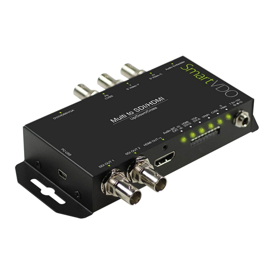
Front Panel Component Function SDI Output Port From your SDI Display Device plug into this ports HDMI output Port From your HDMI Display Device plug into this port Input Port/ Audio The LEDs are indicate Input Ports and Audio source LED Source Control the Box ( Input Port/Audio/Output Dipswitch... -
Page 5: Side Panel
Side Panel Component Function USB Port Upgrade firmware/Control Box From PC... -
Page 6: Dipswitch/Led Control
DipSwitch/LED Control Component Function Five of kinds input source be support Input Source ( DVI-D/DV-A/YPbPr/CVBS/S-Video) Two of kinds Audio input source Audio Source (Embedded audio/L/R Audio) Output format Control Box to switch Output Format. Input Source: VPC-MX1 Box can choose one of three standard inputSource by DipSwitch. Input Source Dipswitch Indicates DVI-D(HDMI) - Page 7 Audio Source: VPC-MX1 Box can be select audio source from L/R Audio. Resolution Dipswitch Indicates Internal (Default) L/R Audio Output Format: VPC-MX1box can be select 16 of kinds output format. Resolution Dipswitch Indicates Resolution 1920x1080p60 1920x1080i60 1920x1080p59 1920x1080i59 1920x1080p50 1920x1080i50 1920x1080p30...
- Page 8 LED Indicate: 2 3 4 5 Component Function The LED is indicate Audio Source Internal/L/R Audio indicate DVI-D(HDMI) The LED is indicate DVI-D Signal indicate DVI-A(VGA) The LED is indicate DVI-A Signal indicate The LEDs is indicate YPbPr Signal YPbPr indicate CVBS...
- Page 9 1. DVI-D + L/R Audio: DVI-D + L/R Audio DVI-D DVI-A YPbPr Cvbs S-Video ● ○ ○ ○ ○ Locked ● ○ ○ ○ ○ Un-locked ●(Blinking) ○ ○ ○ ○ MicroVision 2. DVI-A+ L/R Audio: DVI-A + L/R Audio DVI-D DVI-A YPbPr...
- Page 10 3. YPbPr + L/R Audio: YPbPr + L/R Audio DVI-D DVI-A YPbPr Cvbs S-Video ○ ○ ● ○ ○ Locked ○ ○ ● ○ ○ Un-locked 4. Composite (CVBS) + L/R Audio: Composite(CVBS) + L/R Audio DVI-D DVI-A YPbPr Cvbs S-Video ○...
- Page 11 5. S-VIDEO + L/R Audio Composite(CVBS) + L/R Audio DVI-D DVI-A YPbPr Cvbs S-Video ○ ○ ○ ○ ● Locked ○ ○ ○ ○ ● Un-locked ○ ○ ○ ○ ●(Blinking) MicroVision 6. Audio Select: DVI-D + L/R Audio ● Internal Audio ●...
-
Page 12: Installation
Installation MULTI2SDI-PRO installation consists of the following: 1. Disconnect +12DC adaptor to converter. 2. Connect Video Source to the Input Connector. 3. Connect Display Equipment to the output’s connector 4. Connect the +12DC adaptor to the converter. Package Contents The MULTI2SDI-PRO package contains the following items: ... -
Page 13: Specifications
Specifications DESCRIPTION MULTI2SDI-PRO SDI Format SD-SDI, HD-SDI & 3G-SDI SDI Transition Rate 2.970Gb/s, 10485Gb/s and 270Mb/s HDMI(DVI-D) : 8-Channel L/R Audio : a. only 2 channel and splitter to 8 channel (HDMI/SDI Audio Support out) b. Input impedance = 10K. c. - Page 14 Dimension L:153mm x W:63.3mm xH:26mm Power Source Power Adapter: AC 100 ~ 240 V/DC (+9 ~ 15 V) 0~50°C [32~114°F] Operation Temperature Storage Temperature -20~+60°C...
-
Page 15: Firmware Upload
Firmware Upload Firmware is upgradable in the field using the integrated USB port How to Firmware upgrade: Step 1. Open Upload Firmware Program tools.exe and connect box to PC by USB Cable. Step 2. Plug and un-plug “DC adapter” to power on/off the converter box (the connection check status will be changed to “Connect”) - Page 16 Step 3. Plug and un-plug “DC adapter” again (the connection check status will be changed to “Connected”) and Please click the Open File button to select the firmware bin file. Step 4. Please click “Start’ Button to proceed with new firmware programming. The PASS message will appear when the procedures finished.
-
Page 17: Appendix Table A
Appendix Table A Support Input Format: 720x480i60 720x576i50 720x480 p60 720x576 p50 1280x720p60 1280x720p50 1920x1080i60 1920x1080i50 1920x1080p24 1920x1080p25 1920x1080p30 1920x1080p60 1920x1080p50 640x350p85 640x400p85 720x400p85 640x480p60 640x480p72 640x480p75 640x480p85 800x600p56 800x600p60 800x600p72 800x600p75 800x600p85 848x480p60 1024x768p50 1024x768p59 1024x768p60 1024x768p70 1024x768p75 1024x768p85 1152x864p70 1152x864p75 1280x768pRB... -
Page 18: Update List
Update List Data Version Command 2014.11.11 V1.0 1. Release 2016.08.22 V1.2 1. Change product picture.
Need help?
Do you have a question about the Multi to SDI/HDMI and is the answer not in the manual?
Questions and answers