Advertisement
Quick Links
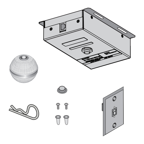
Polycom
Ceiling Microphone Array
®
If you are setting up a Polycom Ceiling Microphone Array, begin on page 2.
If you are setting up a Polycom Ceiling Microphone Array Extension Kit, begin on page 8.
If you are setting up a Polycom telepresence system, refer to the Installation Guide for your
ITP product.
Before you begin, make sure that your ceiling can support up to .9 kg (2 lbs). Also, verify
that the installation parameters described in this document comply with the code
requirements in your local jurisdiction.
© 2018, Polycom, Inc. All rights reserved. POLYCOM® and the names and marks associated with Polycom's products are trademarks and/or
service marks of Polycom, Inc. and are registered and/or common law marks in the United States and various other countries.
By using this product, you are agreeing to the terms of the End User License Agreement (EULA) at: http://documents.polycom.com/indexes/licenses.
If you do not agree to the terms of the EULA, do not use the product, and you may return it in the original packaging to the seller from whom you
www.polycom.com
purchased the product.
August 2018
1725-27017-007E
SETUP SHEET
Advertisement

Related Manuals for Polycom Ceiling Microphone Array


Summary of Contents for Polycom Ceiling Microphone Array
- Page 1 © 2018, Polycom, Inc. All rights reserved. POLYCOM® and the names and marks associated with Polycom’s products are trademarks and/or service marks of Polycom, Inc. and are registered and/or common law marks in the United States and various other countries.
- Page 2 Ensure that the the length of the cable as needed. cables meet all local building code regulations. Polycom Ceiling Microphone Array Setup Sheet...
- Page 3 Be sure that the length of wire you use to secure the electronics enclosure is short enough to prevent the enclosure from striking the person removing the ceiling tile. Polycom Ceiling Microphone Array Setup Sheet...
- Page 4 For suspended ceilings (continued) 15.2 m (50’ ) ~ 3.1 m (10’) .64 cm (.25”) 4.10 cm (1.614”) 4.13 cm (1.625”) 4.10 cm (1.614”) .64 cm (.25”) SoundStructure C16 Polycom Ceiling Microphone Array Setup Sheet...
- Page 5 Step 16. 15.2 m (50’ ) Point the dot (located on the band around the middle of the microphone ball) toward the main display. ~ 3.1 m (10’) SoundStructure C16 Polycom Ceiling Microphone Array Setup Sheet...
- Page 6 For all ceilings (continued) Polycom HDX 8000, Polycom HDX 7000, and Polycom HDX 6000 Polycom RealPresence Group Series 300/310, 500, and 700 HDX 8000 HDX 7000 HDX 6000 RealPresence Systems Group Series 300/310, 500, and 700 Systems RJ-45 to Walta 3.1 m (10’)
- Page 7 Polycom SoundStructure Group Series 300/310 Polycom RealPresence If you plan to install another Ceiling Microphone Group Series 500 Array in the same room, refer to Polycom Polycom RealPresence Ceiling Microphone Array Extension Kit Setup Group Series 700 Sheet on Page 8.
- Page 8 Polycom Ceiling Microphone Array Extension Kit .6 m (2 ft) 2457-26759-024 7.5 m (25 ft) plenum crossover (Use between two electronics enclosures.) 2457-24009-001 Second 7.5 m (25 ft) plenum crossover (Use between second and third electronics Verify that the number of pins on the enclosures for TPX HD 306M, Version 2.0...
- Page 9 Be sure that the length of wire you use to secure the electronics enclosure is short enough to prevent the enclosure from striking the person removing the ceiling tile. Polycom Ceiling Microphone Array Setup Sheet...
- Page 10 For suspended ceilings (continued) Note that the ceiling microphone array boxes and cables are above the suspended ceiling. 7.6 m (25’) (Do not use the non-plenum straight-through 3.1 m (10 ‘) cable) For ceilings that are not suspended Point the dot (located on the band around the middle of the microphone ball) toward the main display.
- Page 11 Polycom SoundStructure C-Series Systems Polycom RealPresence Group Series Systems and HDX Systems For information about optimally placing the microphones to send stereo audio for Polycom SoundStructure Systems, refer to For information about optimally placing the the SoundStructure Design Guide, microphones to send stereo audio for Polycom available at http://support.polycom.com.
Need help?
Do you have a question about the Ceiling Microphone Array and is the answer not in the manual?
Questions and answers