Advertisement
Quick Links
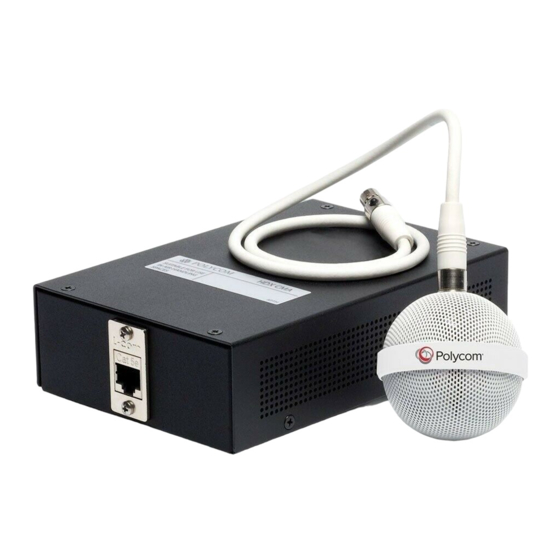
Setting up the
Polycom® HDX™
Ceiling Microphone Array Series
If you are setting up a Polycom HDX Ceiling Microphone Array with a Polycom HDX
System or a Polycom
If you are setting up a Polycom HDX Ceiling Microphone Array Extension Kit with a
Polycom HDX System or a Polycom SoundStructure C-Series System, begin on page 12.
If you are setting up a Polycom
Microphone Array by beginning on page 2, and install the second Ceiling Microphone
Array by beginning on page 12.
Before you begin, make sure that your ceiling can support up to 2 lbs (.9 kg).
©2007, Polycom, Inc. All rights reserved. Polycom® and the Polycom logo are registered trademarks
and HDX™, SoundStructure™, and TPX™ are trademarks of Polycom, Inc.
SoundStructure™
C-Series System, begin on page 2.
TPX™
HD 306M System, install the first Ceiling
November 2007
1725-27017-002/A
Advertisement

Related Manuals for Polycom HDX Ceiling Microphone Array Series


Summary of Contents for Polycom HDX Ceiling Microphone Array Series
- Page 1 Setting up the Polycom® HDX™ Ceiling Microphone Array Series If you are setting up a Polycom HDX Ceiling Microphone Array with a Polycom HDX System or a Polycom SoundStructure™ C-Series System, begin on page 2. If you are setting up a Polycom HDX Ceiling Microphone Array Extension Kit with a Polycom HDX System or a Polycom SoundStructure C-Series System, begin on page 12.
- Page 2 Note: If you are creating your own cables, refer to the Integrator’s Reference Manual for Polycom HDX Systems for cable pin-outs. You can find this document at www.polycom.com/videodocumentation. For suspended ceilings Setting up the Polycom HDX Ceiling Microphone Array Series...
- Page 3 Be sure that the length of wire you use to secure the electronics enclosure is short enough to prevent the enclosure from striking the person removing the ceiling tile. Setting up the Polycom HDX Ceiling Microphone Array Series...
- Page 4 1.614”(4.10 cm) Align the enclosure so that, .25”(.64 cm) when the Microphone Array is attached, the dot on the Microphone Array points towards the main display as shown in step 7. Setting up the Polycom HDX Ceiling Microphone Array Series...
- Page 5 (cont.) For suspended ceilings For Polycom HDX Systems 50’ (15.2 m) ~ 10’ (3.1 m) (cont.) For Polycom SoundStructure C-Series Systems 50’ (15.2 m) ~ 10’ (3.1 m) SoundStructure C16 Setting up the Polycom HDX Ceiling Microphone Array Series...
- Page 6 Each X in the illustration above shows approximately purpose table. where the Ceiling Microphone Arrays should be placed. (cont.) For Polycom TPX HD 306M Systems 50’ (15.2 m) ~ 10’ (3.1 m) Setting up the Polycom HDX Ceiling Microphone Array Series...
- Page 7 PIN 7: CTS PIN 8: RTS Systems RS-232 REMOTE CONTROL 1 C-LINK2 OBAM REMOTE CONTROL 2 SoundStructure C16 C-LINK2 SoundStructure C16 RJ-45 10’ (3.1 m) to Walta connector adapter 10’ (3.1 m) Setting up the Polycom HDX Ceiling Microphone Array Series...
- Page 8 Systems 50’ (15.2 m) 50’ (15.2 m) ~ 10’ ~ 10’ (3.1 m) (3.1 m) Refer to step 4c on page 6 for information about Ceiling Microphone SoundStructure C16 Array placement. Setting up the Polycom HDX Ceiling Microphone Array Series...
- Page 9 PIN 3: RXD PIN 5: GROUND PIN 7: CTS PIN 8: RTS RS-232 REMOTE CONTROL 1 Systems C-LINK2 OBAM REMOTE CONTROL 2 SoundStructure C16 C-LINK2 SoundStructure C16 RJ-45 to Walta connector adapter Setting up the Polycom HDX Ceiling Microphone Array Series...
- Page 10 TPX HD 306M Systems: You must point the dot (located on the band around the middle of the microphone ball) towards the front of the room. Setting up the Polycom HDX Ceiling Microphone Array Series...
- Page 11 For Polycom HDX Systems For Polycom SoundStructure C-Series Systems For information about how to optimally place the microphones to send stereo audio for Polycom HDX or SoundStructure Systems, refer to the Administrator’s Guide for Polycom HDX Systems or the Sound- Structure Design Guide.
- Page 12 (use between two electronics enclosures) Note: If you are creating your own cables, refer to the Integrator’s Reference Manual for Polycom HDX Systems for cable pin-outs. You can find this document at www.polycom.com/videodocumentation. For suspended ceilings Setting up the Polycom HDX Ceiling Microphone Array Series...
- Page 13 Be sure that the length of wire you use to secure the electronics enclosure is short enough to prevent the enclosure from striking the person removing the ceiling tile. Setting up the Polycom HDX Ceiling Microphone Array Series...
- Page 14 Align the enclosure so that, when the Microphone Array is attached, the dot on the Microphone Array points towards the main display as shown in step 6. Setting up the Polycom HDX Ceiling Microphone Array Series...
- Page 15 TPX HD 306M Systems: You must point the dot (located on the band around the middle of the microphone ball) towards the front of the room. Setting up the Polycom HDX Ceiling Microphone Array Series...
- Page 16 For Polycom HDX Systems For Polycom SoundStructure C-Series Systems For information about how to optimally place the microphones to send stereo audio for Polycom HDX or SoundStructure Systems, refer to the Administrator’s Guide for Polycom HDX Systems or the Sound- Structure Design Guide.
Need help?
Do you have a question about the HDX Ceiling Microphone Array Series and is the answer not in the manual?
Questions and answers