Table of Contents
Advertisement
INSTRUCTION HANDBOOK
Electric Stacker ECL 10
WARNING
Do not use the electric truck before reading
and understanding these operating
instructions.
NOTE:
Please check the designation of your
present type at the last page of this
document as well as on the ID-plate.
Keep for future reference.
Version 03/2014
ECL10‐SMS‐004_EN
Advertisement
Table of Contents

Related Manuals for Noblelift ECL 10


Summary of Contents for Noblelift ECL 10
- Page 1 INSTRUCTION HANDBOOK Electric Stacker ECL 10 WARNING Do not use the electric truck before reading and understanding these operating instructions. Version 03/2014 NOTE: Please check the designation of your ECL10‐SMS‐004_EN present type at the last page of this document as well as on the ID-plate.
- Page 2 FOREWORD Before operating the electric stacker, read this ORIGINAL INSTRUCTION HANDBOOK carefully and understand the usage of the truck completely. Improper operation could create danger. This handbook describes the usage of different electric stackers. When operating and servicing the truck, make sure, that it applies to your type. Chapter 11 describes specialized stipulations and regulations for the American market.
-
Page 3: Table Of Contents
TABLE OF CONTENTS 1. CORRECT APPLICATION .......................3 2. DESCRIPTION OF THE STACKER ....................4 a. Overview of the main components ....................4 b. Main technical data ........................5 c. Description of the safety devices and warning labels (Europe and other, excepting USA) ...7 d. -
Page 4: Correct Application
1. CORRECT APPLICATION It is only allowed to use this electric stacker according to this instruction handbook. The in this handbook described trucks are self propelled pedestrian controlled electric power stacker, with electrically operated lifting function. The trucks are designed for stacking operations in dedicated racking by lifting and lowering the palletized load up to the desired lifting height. -
Page 5: Description Of The Stacker
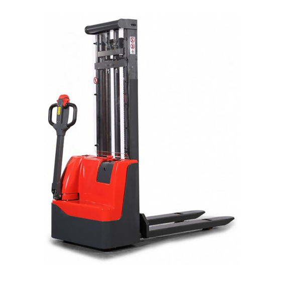
2. DESCRIPTION OF THE STACKER Overview of the main components Fig. 1: Overview main components Key switch 10 Drive wheel Discharge indicator and charging 11 Castors indicating LED 12 Safety (belly) button Emergency button 13 Accelerator (butterfly- switch) Main cover 14 Multifunction tiller Forks 15 Front panel... -
Page 6: Main Technical Data
Main technical data Table1: Main technical data for standard version Fig. 2: Technical data Table 1: Main technical data for standard version Technical data sheet for industrial trucks acc. to VDI 2198 Manufacturer`s type designation 1029 1029 M Drive Battery Operator type Pedestrian Q (t) - Page 7 (mm) 4.19 Overall length 1800 1638 4.20 Length to face of forks (mm) 4.21 Overall width (mm) 1250 4.22 Fork dimensions s/e/l (mm) 60/150/1150 35/100/1150 4.25 Distance between fork- arms (mm) 570/ 685 282 - 800 4.32 Ground clearance, centre of wheelbase (mm) 4.33 Aisle width for pallets 1000X1200 crossways...
-
Page 8: Description Of The Safety Devices And Warning Labels (Europe And Other, Excepting Usa)
Description of the safety devices and warning labels (Europe and other, excepting USA) For the USA –market, the description of the safety and warning labels is mentioned in chapter 11. Crane hook label Warning decal: Do not step under or (12) on the forks C Residual lift capacity sticker... -
Page 9: Warnings, Residual Risk And Safety Instructions
WARNINGS, RESIDUAL RISK AND SAFETY INSTRUCTIONS DO NOT Drive outside the stacking operation with a lifted load higher than the lifting point. Put foot or hand under or into the lifting mechanism. Allow other person than the operator to stand in front of or behind the truck when it is moving or lifting/lowering. -
Page 10: Lifting/ Transportation
Type ECL 1016 ECL 1020 ECL 1029 ECL 1016M ECL 1020M ECL 1029M Commissioning weight [kg] Version/ Lift [mm] 1600 2000 2900 1600 2000 2900 Type ECL 1032 ECL 1035 ECL 1032M ECL 1035M Commissioning weight [kg] Version/ Lift [mm] 3200 3500 3200... -
Page 11: Decommissioning
Decommissioning For storage, remove the load, lower the truck to the lowest position, grease all in this handbook mentioned greasing points (regular inspection), eventual protect the truck against corrosion and dust. Remove the batteries and jack the truck safety, so that there will be no flattening after storage. For final decommissioning hand the truck to a designated recycling company. -
Page 12: Parking
Make sure, that the load is palletized and stable and that the daily inspection is carried out. For starting, insert the key and turn it clockwise to the “ON”- position. The key can be used only used on pedestrian controlled power stacker. Eventually before inserting the key, the emergency button must be pulled carefully. -
Page 13: Travelling
Travelling TRAVEL ON INCLINES ONLY WITH THE LOAD FACING UPHILL DO NOT TRAVEL ON INCLINES MORE THAN SPECIFIED WITH THE TECHNICAL DATA. TRAVELLING IS ONLY ALLOWED IF THE FORKS ARE LOWERED DOWN TO THE LIFTING POINT (<300MM). After starting the truck by turning the inserted key to the “ON”- position (fig. -
Page 14: Malfunctions
button is activated, the truck decelerates and/ or starts travelling into the backwards direction (‘Bw.’) for a short distance and stops. Please consider, that this button also operates, if the truck is not travelling and the tiller is in the operating zone. Malfunctions If there are any malfunctions or the truck is inoperative, please stop using the truck and activate the emergency button (3) by pushing it. -
Page 15: Replacement
Replacement Park the truck securely and switch off the stacker with the key (1) and activate the emergency button (3). Unbolt the 2 screws on the main cover and remove the cover. Unbolt the screws of the negative terminals (indicated with ‘-‘) firstly, then unbolt the screws of the positive terminals (indicated with ‘+’) and put the cables aside. -
Page 16: Regular Maintenance
Charging is finished until the charging LED (fig.14,15) produces permanent green light. The charger then goes into a floating mode to prevent the battery against damages. Following table shows the function of the LED-status: Table 3: LED-Status LED- signal Function Battery discharged Orange Charging... - Page 17 Check mast and chain for corrosion, deformation or damages, replace if necessary 10 Check the gearbox for noise and leakage 11 Check the wheels for deformation and damages, replace if necessary 12 Lubricate the steering bearing ...
-
Page 18: Lubricating Points
Lubricating points Lubricate the marked points according to the maintenance checklist. required grease specification is: DIN 51825, standard grease. Bearings in wheels Main frame post Chain Hydraulic system Steering bearing Gear box Fig. 16: Lubricating points Check and refill hydraulic oil The required hydraulic fluid- type is ... -
Page 19: Removing, Reattaching Guarding
Removing, reattaching guarding DO NOT USE THIUS TRUCK, IF THE GUARDING IS DAMAGED OR NOT CORRECTLY ASSEMBLED! If the guarding needs to be removed, unbolt the fixing screws and remove the screen carefully. The screws will remain with the screen. For reattaching place the screen to the right position and fix each screw correctly. - Page 20 Only travelling in The accelerator and the Check the accelerator and the one direction connections are damaged. connections. The battery is discharged. Check the battery status at the discharge indicator The stacker only The electromagnetic brake is Check the electromagnetic travels very slowly engaged.
-
Page 21: Wiring/ Circuit Diagram
8. WIRING/ CIRCUIT DIAGRAM Electrical circuit diagram Fuses ECL10 FU1 : 10 A FU2 : 0,5 A FU01 : 60 A FU02 : 100 A Fig. 19: Electric diagram ECL10... -
Page 22: Hydraulic Circuit
Hydraulic circuit Lift cylinder Lowering valve Pressure valve Throttle valve Hydraulic power pack (motor and pump) Oil tank Fig. 20: Hydraulic circuit ECL10... -
Page 23: Specialized Stipulations For The Us- American Market
9. SPECIALIZED STIPULATIONS FOR THE US- AMERICAN MARKET The content in this chapter is specialized for the US-American market. Foreword/ Compliance Operating this truck requires knowledge which can be acquired from this instruction handbook. This handbook must be kept available throughout the entire period of use of the industrial truck. -
Page 24: Description Warning Labels (Only Us- Market)
b. Description warning labels (only US- market) Fig. 30: Warning labels and safety devices (only USA) A Crane hook label Sign Caution charger B (used only outside US) Sign danger battery C ResiduaI lift capacity sticker Sign warning battery size D Sticker to read and follow these Sign warning electrical devices instructions... - Page 25 Sign read and follow this instruction (B) Sign warning electrical devices (K) Sign warning stay clear stop truck (G) Sign danger not riding (L) Sign danger being crushed (M) Sign not under, on forks Sign Caution charger (H) Sign danger battery (I) Sign warning battery size (J)
-
Page 26: Declaration Of Conformity (Valid, If Sold Within The Eu)
10. DECLARATION OF CONFORMITY (valid, if sold within the EU) [GB] CE Declaration of Conformity The signatory hereby declares that the specified machine conforms to the EU Directive 2006/42/EC (Machine Directive) and 2004/108/EEC (Electro-Magnetic Compatibility, EMC) including their amendments as translated into national legislation of the member countries. The signatory is individually authorized to compile the technical documents. - Page 27 [N] EU-KONFORMITETSERKLÆRING Undertegnede bekrefter hermed at de enkelte betegnede maskin med kraftdrift tilsvarer de europeiske retningslinjene 2006/42/EC (maskinretningslinje) og 2004/108/EEC (elektromagnetisk fordraglighet - EMV) inklusiv disses endringer og den tilsvarende rettsforordning til omsetning av nasjonal rett. Hver undertegnede er fullmektig til å sette sammen de tekniske dokumentene. [PL] DEKLARACJA ZGODNOŚCI Z NORMAMI UE Niżej podpisani potwierdzają...
- Page 28 Electric Stacker ECL10 Electric Stacker ECL 10M...
- Page 29 ECL10-BPT-001 Spare parts list Electric Stacker ECL10 Version 02/2015 ECL10‐BPT‐006_EN 起始车辆识别号:30150200167 起始日期:2015 年 2 月 更改文件号:Y2015-013 ...
- Page 30 Contents FIG. 1 MAIN COMPONENTS ........................... 3 FIG. 2 FORK ................................5 FIG. 3 SIDEWAYS CASTOR............................6 FIG. 4 LOAD WHEEL ..............................7 FIG. 5 MAST ASSEMBLY............................8 FIG. 6 ELECTRONIC CONTROL BOARD ASSEMBLY ..................10 FIG. 7 MAIN HARNESS............................12 FIG.8 ELECTRIC PARTS AND COMPONENTS ....................
- Page 31 Fig. 1 Main components...
- Page 32 Parts No. Name Qty. Remarks 9000002061 Single mast 2000 9000002097 Single mast 1600 9000002119 Protective plate Double mast 2900 9000009969 Double mast 3200 9000009980 Double mast 3500 0000023555 Screw 1000423003 Screw 0000023076 Screw 9000002060 Open plate 9000002059 Tank cover 9000002023 Single mast 570X2000 9000002092 Single mast 570X1600...
- Page 33 Fig. 2 Fork Parts No. Name Qty. Remarks 9000002010 Single mast 570 9000005949 Single mast 685 Welded fork 9000002102 Double mast 570 9000005962 Double mast 685 2530402002 Bearing 0000026013 Circlip for shaft – A type 2500525001 Washer 2500502003 Side cushion...
- Page 34 Fig. 3 Sideways castor Name Qty. Remarks Parts No. 0000026008 Circlip for shaft Bearing seat 2000405001 Angular contact bearing 0000027013 2000413001 Sleeve 0000026010 Circlip 0000024015 Self- locking nut 2000401007 Wheel frame Bolt 0000023111 Shaft sleeve 2000413002 1000525001 Washer 0000027001 Bearing 2020416001 Wheel Screw...
- Page 35 Fig. 4 Load wheel Parts No. Name Qty. Remarks 2000416003 Load wheel 0000028055 Dowel pin heavy 1030507004 Axle 0000027001 Bearing 1000525001 Washer...
- Page 36 Fig. 5 Mast Assembly 5.1 Double Mast...
- Page 37 Parts No. Name Qty. Remarks 9000002124 2900 9000009973 Inner mast welding 3200 9000009984 3500 570X2900 9000002108 Whole chassis, also see fig. 1 9000005964 685X2900 9000009966 570X3200 Welded chassis 9000009988 685X3200 9000009977 570X3500 9000009990 685X3500 2530402002 Bearing 0000026013 Circlip for shaft-A type 2500525001 Helical washer Quality depends on situation...
- Page 38 Fig. 6 Electronic control board assembly...
- Page 39 Parts No. Name Qty. Remarks 9000002066 Aluminum plate 9000009802 Controller CURTIS1212P-2501 0000023033 Screw 0000025018 Spring washer 1000434007 Fuse holder SYY 0000025019 Flat washer 0000023211 Screw 2210434004 Bolted fuse 0000023071 Screw 9000005985 Temperature protection module BD-W-115-N 0000023516 Screw 0000025014 Flat washer 0000025015 Spring washer 1000404005...
- Page 40 Fig. 7 Main Harness Parts No. Name Qty. Remarks 9000002409 B0 wire 9000002410 B+ wire 9000002411 1B+ wire 9000002412 2B+ wire 9000002413 3B+ wire 9000002414 4B+ wire 9000002415 PB- wire 9000002416 B- wire 9000002417 Driving wheel harness 9000002418 Charger anode B+ wire 1020434003 Copper bar 1 9000008788...
- Page 41 Fig.8 Electric parts and components...
- Page 42 Parts No. Name Qty. Remarks 2040634001 Micro switch 2040603002 Micro switch protective cover 0000023033 Screw 0000023107 Screw 0000025015 Spring washer Add 6 piece 0000025014 Flat washer Add 6 piece 9000002065 Electronic control assembly 1000432001 Battery 12V/85Ah Optional 2100432001 Battery 12V/106Ah 0000025011 Flat washer 0000023012...
- Page 43 9000002079 Approach switch fixed plate 9000007427 Approach switch NBN5-FT-E2 single Mast 9000007428 Approach switch NBN5-FT-E2 double Mast 0000023075 Screw 0000023042 Screw 9000005937 Cable holder 1010434007 air fan ADDA DC12V 0000023041 Screw 1010404005 Connector 1000434021 One position vehicle fuse holder BD 1010434008 Plug fuse 0000023074...
- Page 44 Fig.9 Hydraulic System 9.1 Single mast hydraulic system Parts No. Name Qty. Remarks 0000026003 Circlip for shaft 0000027001 Bearing 0000026009 Circlip for hole 2510510001 Chain wheel 2500502005 Cylinder joint 0000023067 Screw 9000002081 Cylinder assembly ECL1020...
- Page 45 9000002099 Cylinder assembly ECL1016 2530202002 Cylinder bracket 2000337001 Safety pressure valve assembly 0000022051 Seal washer assembly 2000317002 Straight joint 0000022011 O type rubber seal ring 9000002082 High pressure steel tube 0000023099 Screw 0000023006 Spring washer 0000025106 Flat washer Hydraulic power pack 24V2.2KW2.0 2130300002 volume 0000017002...
- Page 46 9.2 Double mast hydraulic system Remarks Parts No. Name Qty. 0000026003 Circlip for shaft 0000027001 Bearing 0000026009 Circlip for hole 2510510001 Chain wheel 0000023067 Screw 9000002122 ECL1029 Cylinder assembly 9000009971 ECL1032 9000009982 ECL1035...
- Page 47 2530202002 Cylinder bracket 2000337001 Safety anti-explosion valve assembly 0000022051 Seal washer assembly 2000317002 Straight joint 0000022011 O type rubber seal ring 9000002082 High pressure steel tube 0000023099 Screw 0000023006 Spring washer 0000025106 Flat washer 2130300002 Pump station 24V2.2KW2.0 volume 0000017002 Joint JTJ8-G3/8-M16x1.5 9000002082 High pressure rubber tube...
- Page 48 Fig. 10 Cylinder assembly Parts No. Name Qty. Remarks 2000322001 Dust ring 2000322002 Support ring for shaft I type nut 0000024074 Fin thread 0000025033 Spring washer 2010322001 Y type sealing ring 2000322003 Support ring for hole 0000022013 O ring 0000022014 O ring Sealing parts pack...
- Page 49 Fig. 11 Pump system Parts No. Name Qty. Remarks 2130301001 Oil tank 2500217001 Oil suction pipe 2500237001 Gear pump 2500222001 O ring 2500237005 Refill cover 2500215002 Center valve block 2110234001 solenoid valve 2500235002 Overflow valve 2500235003 Check valve 2110234003 Contactor 2110234002 Motor...
- Page 50 Fig.12 Driving system Parts No. Name Qty. Remarks 0000023059 Screw 0000025019 Flat washer 9000002090 Driving wheel cover 0000023044 Screw 0000023089 Screw 9000002089 Handle seat 9000002087 Locating sleeve 0000023042 Screw 9000002086 Bearing seat 0000027048 Bearing...
- Page 51 0090000038 Roller bearing 9000002085 Connecting flange 0000023034 Screw 0000023006 Spring washer 0000025010 Spring washer 9000002088 Locating block 9000001023 Driving wheel 0000023088 Screw...
- Page 52 Fig.13 Instruments board assembly Parts No. Name Qty. Remarks 0090000041 Screw 2240434001 DC power switch ZDK31-250 9000002070 Instruments cover 9000002071 Clipboard 0000024002 I type nut 0000023075 Screw 0000025011 Flat washer C level 0000023089 Screw 1010434002 General key switch LKS-101A 1000123003 Screw 9000009801 Discharge indicator...
- Page 53 Fig.14 Tiller arm assembly...
- Page 54 Name Qty. Remarks Parts No. 0000023061 Screw 0000025004 Spring washer 9000005940 Handle lever welding part 1000123001 Screw 1030418001 Sleeve F=800N Air spring 9000007398 9000005945 Spindle 0000013002 Shoulder sleeve 0000028163 Cylindrical pin heavy 0000025004 Spring washer 0000023089 Screw 9000007427 Proximity switch NBN5-FT-E2 0000023075 Screw 9000002406...
- Page 55 Fig.15 Economic tiller head...
- Page 56 Parts No. Name Qty. Remarks 9000002189 Handle seat 9000002175 Left driving switch 9000008334 Accelerator BD-190 9000002177 Accelerator connecting part 9000002188 Sleeve 9000002176 Right driving switch 0000023304 Screw 0000025003 Spring washer 0000025026 Flat washer 0090000190 Lock screw 0090000189 Sunk screw 9000002179 Handle downside cover 0000023138 Sunk screw...
- Page 57 Fig.16 Driving wheel assembly Name Qty. Remarks Parts No. Retainer ring 0000026005 Bearing 0000027068 0000036005 Flat key A 5X18 9000002136 Bearing shaft 19EL100005 9000002137 Reduction box body 19EL100001 1070309001 Pinion 0000026004 Retainer ring 0000025009 Spring washer 0000036002 Flat key 5X15 0000025020 Washer...
- Page 58 9000002138 Permanent magnet motor 0.45kW 0000023061 Screw 0000027086 Bearing 1070309002 Gear wheel 0090000178 Oil seal ring 9000002139 Inner gear ring 19EL100008 0090000179 Bearing 0090000180 Retainer ring 0090000181 O ring 9000002140 Filter seal seat 19EL100009 9000002141 Wheel 19EL110000 0000025006 Spring washer 0090000182 Screw 9000002142...
- Page 59 Fig.17 Sticker for EU Art No. Description Qty. Note 9000005967 Sign hook 9000003923 Forbidden under/above the fork 9000005968 Sign load curve 9000003570 Sign read and follow this instruction 9000003573 ‘No passengers’ decal...
- Page 60 Fig.18 Sticker for US...
- Page 61 Art No. Description Qty. Note 9000005967 Sign hook 9000005968 Sign load curve 9000003570 Sign read and follow this instruction 9000003575 Sign warning stay clear stop truck 9000003576 Sign caution charger 9000003577 Sign danger battery 9000003578 Sign warning battery size 9000003579 Sign warning electrical devices 9000003580 Sign danger not riding...
- Page 62 ECL10-BPT-001 Spare parts list Electric Stacker ECL 10M Version 02/2015 From truck identification number: 30150200167 ECL 10M-BPT-003-EN...
- Page 63 Catalogue FIG.1 STICKER FOR EU ..................3 FIG.2 STICKER FOR US ..................4 FIG. 3 APPEARANCE....................6 FIG. 4 FORK........................ 8 FIG. 5 LOAD BACKREST (OPTIONAL) ..............9 FIG. 6 CASTOR ......................10 FIG. 7 LOAD WHEEL....................12 FIG. 8 MAST ASSEMBLY..................13 FIG.
- Page 64 Fig.1 S ticker for EU Fig.1 Sticker for EU Art No. Description Qty. Note standard 9000005967 Sign hook 9000003923 Forbidden under/above the fork 9000005968 Sign load curve 9000003570 Sign read and follow this instruction 9000003573 ‘No passengers’ decal...
- Page 65 Fig.2 S ticker for US...
- Page 66 Fig.2 Sticker for US Art No. Description Qty. Note standard 9000005967 Sign hook 9000005968 Sign load curve 9000003570 Sign read and follow this instruction 9000003575 Sign warning stay clear stop truck 9000003576 Sign caution charger 9000003577 Sign danger battery 9000003578 Sign warning battery size 9000003579 Sign warning electrical devices...
- Page 67 Fig. 3 Appearance...
- Page 68 Fig. 3 Appearance Name Qty. Remarks standard Parts No. 9000002061 One-stage-mast 9000002097 One-stage-mast Protective plate 9000002119 Two-stage-mast 9000009980 Two-stage-mast 9000009969 Two-stage-mast 0000023555 Screw M6x16 GB/T70.2=ISO7380 1000423003 Screw M10X30 0000023076 Screw M5x12 GB/T70.1=ISO4762 9000002060 Opening plate 9000002059 Box cover 9000007457 One-stage-mast 9000007475 One-stage-mast Welded chassis...
- Page 69 Fig. 4 Fork Fig. 4 Fork Parts No. Name Qty. Remarks standard 2080501001 Fork 2090501001 Fork 1150 9000007453 Fork holder 0000023088 Screw M10x25 GB/T70.1=ISO4762 2530402002 Roller GB/T894.1 0000026013 Retaining ring 2500525001 Washer 2500502003 Side block 9000010404 wheel accessories...
- Page 70 Fig. 5 Load backrest (optional) Fig. 5 Load backrest (optional) Parts No. Name Qty. Remarks standard 2100501004 Load backrest 0000023034 Screw M10x20 GB/T70.1=ISO4762 0000025002 Washer GB/T95...
- Page 71 Fig. 6 Castor Fig. 6 Castor Parts No. Name Qty. Remarks Standard 0000026008 Retaining ring GB/T894.1 2000405001 Bearing seat 0000027013 Bearing 7206C/DB GB/T292 2000413001 Bushing GB/T893.1 Retaining ring 0000026010 GB/T889.1=ISO7040 0000024015 2000401007 Wheel frame GB/T5782=ISO4014 0000023111 Bolt M14x100 2000413002 Shaft sleeve Washer 1000525001 GB/T276=ISO3290...
- Page 72 GB/T70.1=ISO4762 0000023029 Screw M10x35 GB/T93 0000023006 Spring washer GB/T95 0000025002 Washer 9000005936 Adjusting plate □ 1 2040400001 Steering wheel assembly 9000010408 steering wheel accessories 9000003638 wheel accessories...
- Page 73 Fig. 7 Load wheel Fig. 7 Load wheel Parts No. Name Qty. Remarks standard 2000416003 Load wheel 0000028055 Roll pin 5x40 GB/T879.1=ISO8752 1030507004 Rotating axle 0000027001 Bearing 6204 GB/T276=ISO3290 1000525001 Washer 9000010405 wheel accessories...
- Page 74 Fig. 8 Mast assembly 8.1 Two-stage-mast...
- Page 75 8.1 Two-stage-mast Parts No. Name Qty. Remarks Standard Two-stage-mast 9000002124 2900 Two-stage-mast Inner mast welding 9000009984 3500 Two-stage-mast 9000009973 3200 Two-stage-mast 9000007480 2900 Two-stage-mast 9000010166 Welded chassis 3500 Two-stage-mast 9000010168 3200 2530402002 Roller GB/T894.1 0000026013 Retaining ring 2500525001 Washer 2500502003 Side cushion 0000023172 Screw...
- Page 76 Fig. 9 Electronic control board assembly...
- Page 77 Fig. 9 Electronic control board assembly Parts No. Name Qty. Remarks Standard 9000002066 Aluminum plate 9000009802 Controller CURTIS1212P-2501 0000023033 Screw M4x25 GB/T70.1=ISO4762 0000025018 Standard spring washer GB/T93 1000434007 Fuse seat 0000025019 Washer GB/T95 0000023211 Screw M4x16 GB/T818=ISO7045 2210434004 Fuse 150A GB/T818=ISO7045 0000023071 Screw...
- Page 78 Fig. 10 Main harness Fig. 10 Main Harness Parts No. Name Qty. Remarks Standard 9000002409 B0 wire 9000002410 B+ wire 9000002411 1B+ wire 9000002412 2B+ wire 9000002413 3B+ wire 9000002414 4B+ wire 9000002415 PB- wire 9000002416 B- wire 9000002417 Driving wheel harness 9000002418 Charger anode B+ wire Copper bar 一...
- Page 79 Fig.11 Electric parts and components...
- Page 80 Fig.11 Electric parts and components standard Parts No. Name Remarks 2040634001 Micro switch XZ-15GW22-B Micro switch protective 2040603002 cover 0000023033 Screw M4x25 GB/T70.1=ISO4762 0000023107 Screw M5x16 GB/T70.1=ISO4762 0000025015 Standard spring washer GB/T93 0000025014 Washer GB/T95 9000002065 Electronic control assembly 1000432001 Battery 12V/85Ah Optional 2100432001...
- Page 81 9000002192 LED Fault display assembly 9000002324 Fuse tube 5*20 0.5A 9000002407 Control harness 9000002408 Micro switch harness 9000002079 Proximity switch fixing plate Proximity switch 9000007427 One-stage-mast NBN5-FT-E2 Proximity switch 9000007428 Two-stage-mast NBN5-FT-E2 GB/T70.1=ISO4762 0000023075 Screw M3X20 GB/T70.1=ISO4762 0000023042 Screw M6x10 9000005937 Cable holder 1010434007...
- Page 82 Fig.12 Hy draulic system 12.1 One-stage-mast hydraulic system 12.1 One-stage-mast hydraulic system Parts No. Name Qty. Remarks standard GB/T894.1 0000026003 Retaining ring GB/T276=ISO3290 0000027001 Bearing 6204 GB/T893.1 0000026009 Retaining ring 2510510001 Chain wheel 2500502005 Base 0000023067 Screw M8x16 GB/T70.1=ISO4762 9000002081 Cylinder assembly ECL1020...
- Page 83 9000002099 Cylinder assembly ECL1016 2530202002 Cylinder hoop 2000337001 Safety explosion-proof 0000022051 Combination seal washer 2000317002 Straight joint 0000022011 O rubber seal ring 8x1.8 GB/T3452.1=ISO3601 9000002082 High pressure steel tube GB/T70.1=ISO4762 0000023099 Screw M10x45 GB/T93 0000023006 Standard spring washer GB/T95 0000025106 Washer 2130300002 Pump station...
- Page 84 12.2 T wo-stage-mast hydraulic system 12.2 Two-stage-mast hydraulic system Parts No. Name Qty. Remarks standard 0000026003 Retaining ring GB/T894.1 0000027001 Bearing 6204 GB/T276=ISO3290 0000026009 Retaining ring GB/T893.1 2510510001 Chain wheel 0000023067 Screw M8x16 GB/T70.1=ISO4762 9000002122 ECL1029 Cylinder assembly 9000009971 ECL1032 9000009982 ECL1035...
- Page 85 2530202002 Cylinder hoop Safety explosion-proof 2000337001 Combination seal 0000022051 2000317002 Straight joint GB/T3452.1=ISO3601 0000022011 O rubber seal ring 8x1.8 High pressure steel 9000002082 0000023099 Screw M10x45 GB/T70.1=ISO4762 Standard spring 0000023006 GB/T93 0000025106 Washer GB/T95 Pump station 2130300002 24V2.2KW2.0 0000017002 Joint JTJ8-G3/8-M16x1.5 High pressure rubber 9000002082...
- Page 86 Fig. 13 Cy linder assembly Fig. 13 Cylinder assembly Parts No. Name Qty. Remarks standard 2000322001 Dust ring 40X48-5/6.5 2000322002 Support ring for shaft 40X10-2 GB/T6171= ISO8673 0000024074 M20x1.5 0000025033 Standard spring washer GB/T93 2010322001 Y seal ring 45X35-6 2000322003 Support ring for hole 45X10-2 0000022013...
- Page 87 Fig. 14 Pump system Fig. 14 Pump system Parts No. Name Qty. Remarks standard 2130301001 Oil tank 2500217001 Oil suction pipe 2500237001 Gear pump 2500222001 O ring 2500237005 Refill cover 2500215002 Center valve block 2110234001 solenoid valve 2500235002 Overflow valve 2500235003 Check valve 2110234003...
- Page 88 Fig.15 Driving system...
- Page 89 Fig.15 Driving system Parts No. Name Qty. Remarks standard 0000023059 Screw M4x8 GB/T70.1=ISO4762 0000025019 Washer GB/T95 9000002090 Driving wheel cover 0000023044 Screw M8x20 GB/T70.1=ISO4762 0000023089 Screw M8x12 GB/T70.1=ISO4762 9000002089 Handle seat 9000002087 Locating bushing GB/T70.1=ISO4762 0000023042 Screw M6x10 9000002086 Bearing seat 0000027048 Bearing 6209...
- Page 90 Fig.16 Instrument components Fig.16 Instrument components Parts No. Name Qty. Remarks standard 0090000041 Screw M5x10 GB/T70.2=ISO7380 2240434001 DC power switch ZDK31-250 9000002070 Instruments board 9000002071 Clipboard 0000024002 GB/T6170=ISO4032 0000023075 Screw M3x20 GB/T70.1=ISO4762 0000025011 Washer GB/T95 0000023089 Screw M8x12 GB/T70.1=ISO4762 1010434002 Key switch LKS-101A GB/T70.2=ISO7380 1000123003...
- Page 91 Fig.17 T iller arm assembly...
- Page 92 Fig.17 Tiller arm assembly Parts No. Name Qty. Remarks standard M8x25 0000023061 Screw GB/T70.1=ISO4762 0000025004 Standard spring washer GB/T93 9000005940 Handle lever welding part M8X20 1000123001 Screw 1030418001 Seal bushing F=800N 9000007398 Air spring 9000005945 20X78 Rotating axle 0000013002 20X22X12 Shoulder harness 0000028163...
- Page 93 Fig.18 Economic tiller head...
- Page 94 Fig.18 Economic tiller head Parts No. Name Qty. Remarks standard 9000002189 Tiller seat 9000002175 Left driving switch 9000008334 Accelerator BD-190 9000002177 Accelerator connecting part 9000002188 Bushing 9000002176 Right driving switch 0000023304 Screw M3X12 GB/T70.1=ISO4762 0000025003 Spring washer GB/T93 0000025026 Washer GB/T95 0090000190 Screw...
- Page 95 Fig.19 Driving wheel assembly Fig.19 Driving wheel assembly standard Name Qty. Remarks Parts No. Retaining ring GB/T894.1 0000026005 Bearing 6203 GB/T276=ISO3290 0000027068 0000036005 Flat key A5X18 GB/T1096 9000002136 Gear shaft 9000002137 Gear box 1070309001 Small gear 0000026004 Retainer ring GB/T894.1 0000025009 Spring washer GB/T93...
- Page 96 Permanent magnet motor 9000002138 0000023061 Screw M8X25 GB/T70.1=ISO4762 0000027086 Bearing 61905 GB/T276=ISO3290 1070309002 Gear wheel GB9877 0090000178 Oil seal 160X174X10 9000002139 Inner gear ring 19EL100008 0090000179 Bearing 61824 GB/T276=ISO3290 0090000180 Retaining ring GB/T894.1 0090000181 O ring 115X2.65 GB/T3452.1=ISO3601 9000002140 Filter seal seat 19EL100009 9000002141 Wheel...
- Page 97 Easy worn parts list Qty. Fig./Position Note Art No. Description 2000416003 Small wheels Fig.7/1 Load wheel Castor Fig.6/11 Load wheel Fig.7/4 One-stage mast 0000027001 Bearing Fig.12.1/2 hydraulic system Fig.12.2/2 Two-stage mast hydraulic system Driving wheel 9000002141 Driving wheel Fig.19/21 assembly Driving wheel 9000002143 Carbon brush...
- Page 98 Electric parts and 9000002324 Fuse tube Fig.11/22 components Electric parts and 9000002192 LED fault display assembly Fig.11/21 components Electronic control 9000002322 Relay Fig.9/24 board assembly Tiller micro-switch 9000002190 Fig.18/30 Economic tiller head assembly 1 Tiller micro-switch 9000002473 Fig.18/29 Economic tiller head assembly 2 9000007427 Proximity switch...