Table of Contents
Advertisement
Quick Links
Advertisement
Table of Contents

Summary of Contents for Asymod IIIs
- Page 1 Asymod IIIs Asymmetrical Hi-Fi AM modulator Asymod ® IIIs PATENT PENDING Installation Manual Asymod products are available at www.bxc.mobi Customer support: asyadvice@gmail.com “Asymod” is a registered trademark and may not be reproduced or used by any means or in any form whatsoever. - 1 -...
-
Page 2: Table Of Contents
Asymod IIIs & Stryker SR-955HPC Installation + eSSB……………………………………….…….32 Asymod IIIs & Stryker SR-955HPC + eSSB Settings & Specifications………………………...34 Asymod IIIs & Cobra 2000GTL Installation + eSSB Settings & Specifications…………...41 Asymod III installations (Asymod IIIs Installations start on page 32)……………………………7 ... -
Page 3: General Description
General Description The Asymod IIIs compact design makes it ideal for mobile and base station operation and allows for internal mounting and simple installation in the transceiver with the included hardware and only requires a 12 Volt supply. Improvements in the Asymod IIIs Include selectable passive and active low pass filters, Remote Control on board Solid State switch for ease of installation on multimode transceivers, enhanced RF suppression and single-supply design providing quieter very low noise operation. -
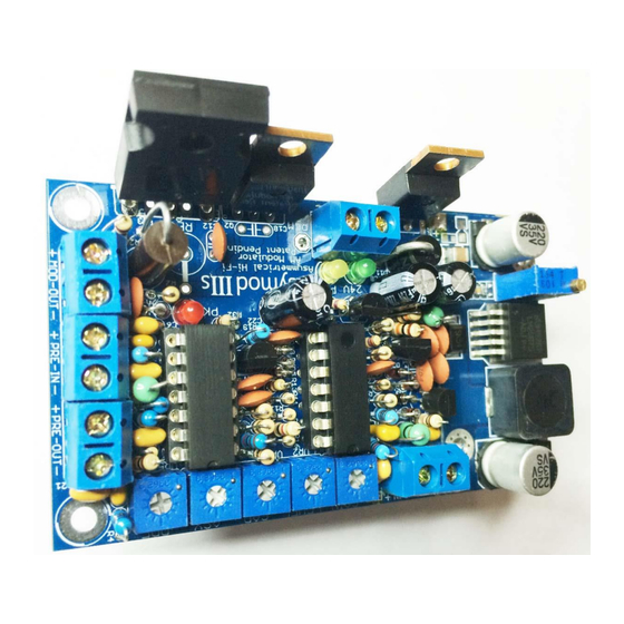
Page 4: Terminal, Component, And Adjustment Locations
ProTools for PC or Mac along with the companion interface such as the Mbox 2 Mini or newer. The Asymod IIIs is NOT designed to give transceivers more RF power, more swing, or loud distorted modulation, as many, which are not accustomed to, or appreciate the high fidelity audio desire. - Page 5 - 5 -...
-
Page 6: A Word About Bias
A Word about Bias The ideal rig to use with the Asymod IIIS, is a dual final, single mode, AM only transceiver. Class C bias or close to it should be employed in multimode transceivers RF final stages to allow for -100% modulation peaks and achieve the correct asymmetry. -
Page 7: Basic Installation For Stryker Sr-955 Hpc
4- Run a wire from L32 to J4 pin as shown. 5- Run a wire from the anode of D515 to the Asymod III +12V input (1) terminal and connect the – input (2) terminal to point (Chassis Ground) as shown. - Page 8 Audio Input Connections - 8 -...
-
Page 9: Advanced Installation With Dpdt Relay For Stryker Sr-955 Hpc
3- Run a wire from the Asymod III, HI-OUT- terminal (4) to point (Chassis Ground). 4- Run a wire from the anode of D515 (FIG. 2) to the Asymod III +12V input (1) terminal and connect the – input (2) terminal to point (Chassis Ground) as shown. - Page 10 3- Run a wire from the Asymod III, HI-OUT- (4) terminal to point (Chassis Ground). 4- Run a wire from the anode of D515 (FIG.2) to the Asymod III +12V input (1) terminal and connect the – input (2) terminal to point (Chassis Ground) as shown.
- Page 11 When SW2 is in the DOWN position the driver and final are diverted to the Asymod III. At this point, the Asymod III is enabled and the mode switch must be set to AM. The transceiver will only transmit on AM via the Asymod III and will be only capable to receive on FM and SSB.
-
Page 12: Stryker Sr-995Hpc Pa Schematic
NOTE: IMPORTANT The Asymod III offers the flexibility to choose from 3 final modulating stage transistor onboard configurations, allowing for TO-220 or TO-247 package transistors. To avoid permanent damage to the onboard DC/DC converter, do not exceed a 1 Watt carrier (dead key) on a single final transceiver, and a 2 Watt carrier (dead key) for a dual final transceiver. - Page 13 Please refer to the DC/DC converter section on page 32 for details. The Asymod III may be set up in any one of the three following onboard configurations: A- Single MJE3055T transistor (T2) with a maximum collector current of 10 Amps. (Standard) B- Dual MJE3055T transistor (T1 &...
- Page 14 It is recommended to use a similar heatsink setup as seen here in FIG. 5B. NOTE: For detailed instructions, please take a look at the following link: http://www.zen183332.zen.co.uk/Aleph/mounting.PDF - 14 -...
-
Page 15: Ptt / Mox Operation
Asymod III. *When using the Asymod III, it is recommended to use a foot pedal or a modified PS/2 or USB mouse as a momentary switch connected to the transceivers microphone jack as the PTT for more comfort and ease of use. -
Page 16: Microphone Installation
Disconnect the wire connected to pin 2. Solder one side of L1 to pin 2. Solder a shielded wire from the other side of L1 and connect it to the Asymod +Line In. Make sure to ground the shield to pin 1. -
Page 17: Installation Block Diagram
Installation Block Diagram Installation for Other Transceivers - 17 -... -
Page 18: Cobra Installation Section
NOTE: IMPORTANT Keep in mind that the transceiver is only the exciter and should not be expected to generate high levels of RF power, it should be expected, however, to generate a clean, perfect modulated wide-band audio signal that can be later amplified with a class C, RF power amplifier to the desired level. It is highly recommended to use dual final transceiver which allow for plenty of headroom and much cooler operation. - Page 19 The Cobra 29 and 25 installation is straight forward and easy to do, simply follow the instructions in the images below. Cobra 25 Fig 7G Cobra 29 Fig 7H - 19 -...
- Page 20 Cobra 2000GTL The Cobra 2000GTL is a multimode transceiver and there is the option to perform the basic or advanced installation to keep SSB mode operable. Points 1 and 2 in Fig 7J are the insertion points TP7 and TP8. If after the installation is complete, -100% modulation cannot be achieved, you can try lowering the bias.
-
Page 21: Galaxy Installation Section
DPDT switch as shown on Fig 7K, connect the TP7 and TP8 board pins to the DPDT switch and finally connect the Asymod III output to the DPDT switch and board ground as seen on FIG. 9 above. Refer to FIG.8 for TP7 and TP8 board location. - Page 22 Fig 9 Fig 10 - 22 -...
-
Page 23: Basic Installation With Bias Modification
Basic Installation with Bias Modification Fig 11. Galaxy DX 44 single final AM/FM Transceiver Figure 11 shows a perfect example of a Class C biased RF final stage. L35 and L47 pull the bases of TR43 and TR44 far down and the Q-point is set some way below the cut-off point in the DC load line. As a result the transistors will start conducting only after the input signal amplitude has risen above the base emitter voltage (Vbe~0.7V). - Page 24 Fig. 14 shows a basic dual final installation with the class C bias mod on a galaxy DX 99V. Points A, B & C depict the locations of inductors L47, L50 & L35. These three inductors act as an RF choke when applying the bias voltage to the base of the driver and finals so that the RF does not pass into the DC bias circuit.
-
Page 25: Dual Final Basic Installation With Bias Mod
Galaxy DX 99V Dual Final Basic Installation with Bias Mod. Fig 14 Fig. 15 shows a basic single final installation with the class C bias mod on a galaxy DX 949. Points A & B depict the locations of inductors L37 & L33. These two inductors act as an RF choke when applying the bias voltage to the base of the driver and final so that the RF does not pass into the DC bias circuit. - Page 26 Fig 15 To convert to class C bias, simply unsolder inductors L37 & L33 at the long lead side at points A & B, as seen on Fig. 15, which is the side that should be connected to the bias circuit, in this case, VR12 & VR10. Solder the long lead side of L37 &...
- Page 27 For Fig 16. Galaxy DX 919 Single Transistor Final installation, cut at the red X and connect to ground at the red circled points. For Fig 17. Galaxy DX 2527 Dual Transistor Final, cut at the red X and connect to ground at the red circled points.
-
Page 28: Advanced Installation With Bias Switching Modification
AB bias for SSB operation to class C bias during AM operation and at the same time switching from Asymod III enabled to regular stock configuration. It requires 6PDT switch for dual final transceivers and a 4PDT switch for single final transceivers. - Page 29 The best way for the multimode transceiver to fully switch over from being a Hi-Fi AM exciter back to its factory configuration automatically is to employ a relay in place of the 6PDT switch or 4PDT switch in the Advanced Installation with Bias Modification above. Simply connect a relay in the same configuration as the switch in the installation above and use the AM mode signal from the mode switch to drive a NPN general purpose transistor, to in turn, drive the relay.
-
Page 30: Outboard Potentiometer Installation
Fig 23. Mode signal relay drive. NOTE: Mode switch configurations and mode signal voltage levels on all of the different transceivers is beyond the scope of this manual. Some transceivers use low level logic to switch modes and care should be taken when using the mode signal from the transceiver, as it might not be able to provide sufficient current to activate a relay, and by putting a load such as a relay might damage the transceiver’s mode switching circuit. -
Page 31: Asymod Iiis & Stryker Sr-955Hpc Installation + Essb
Note: Be sure to install the new DC/DC converter the same direction seen on this image. The Asymod III is equipped with convenient power supply inputs and can be connected to external supplies via the terminal solder pads under the DC/DC converter or on the bottom/copper side of the board as seen on Fig 28. - Page 32 - 32 -...
- Page 33 - 33 -...
- Page 34 Asymod IIIs & Stryker SR-955HPC Settings & Specifications - 34 -...
- Page 35 Asymod IIIs and Stryker SR-955HPC (AM) External Settings Optimal operating audio input levels: ProTools signal generator at 1 kHz at 850 mV p-p, -8dBu, -10dBV. Voice peaks of 1.2V p-p, -6dBu, -7dBV. Line-In & ProTools ProTools session: Stryker SR-955HPC.ptf - 35 -...
- Page 36 Not as in the hour clock. Note: These settings are based on 250% modulation levels. 4 Watt carrier @ 250% mod, 44 Watts PEP (max recommended power setting) Stryker SR-955HPC W10 AM ANL: Fully counter Clockwise (Fig. 1) Asymod IIIs - 36 -...
- Page 37 Carrier: 5.5 Asymmetry: 3 3 Watt carrier @ 250% modulation, 33 Watts PEP Stryker SR-955HPC W10 AM ANL: Fully counter Clockwise (Fig. 1) Asymod IIIs Gain: fully counter clockwise Level: 1.3 Carrier: 5.5 Asymmetry: 1.6 2.5 Watt carrier @ 250% modulation, 25 Watts PEP Stryker SR-955HPC W10 AM ANL: Fully counter Clockwise (Fig.
- Page 38 Carrier: 5.3 Asymmetry: 1.5 2 Watt carrier @ 250% modulation, 22 Watts PEP Stryker SR-955HPC W10 AM ANL: Fully counter Clockwise (Fig. 1) Asymod IIIs Gain: fully counter clockwise Level: 1.2 Carrier: 4.5 Asymmetry: 1.3 1 Watt carrier @ 250% modulation, 11 Watts PEP Stryker SR-955HPC W10 AM ANL: Fully counter Clockwise (Fig.
- Page 39 Level: 1 Carrier: 4.5 Asymmetry: 1.1 ProTools & Stryker 955 settings (SSB) External Settings Line-In & ProTools (Same as above) ProTools session: Stryker SR 955HPC.ptf Mbox 2 Mini Button 1(left) output: at 3 o'clock Mix: fully clockwise Input 1: at 0dB marker Input 2: N/A Microphone In (Front panel microphone connector) When using the microphone input at the front panel with a non-amplified dynamic...
- Page 40 SSB power: Pot W13 SSB LIMIT minimum power clockwise (10 Watts PEP). Maximum power counterclockwise (60 Watts PEP) Fig. 1 Specifications AM TX: Carrier: 1 - 10 Watts Peak Envelope Power: 11 - 55 Watts Modulation: 100% – 350% TX Bandwidth: Up to 10+ kHz (dependent on audio process roll-off) AM RX: Bandwidth: +/- 7.5 kHz Att Band Width: +/- 15 kHz...
- Page 41 Asymod IIIs & Cobra 2000GTL Installation + eSSB, Settings & Specifications - 41 -...
- Page 42 Line-In connector at the (+) lead of C99 and ground shield to nearby available hole. 27- Connect procced audio from Asymod to (-) lead of C99 (O) for SSB to balanced modulator via a 2.2uF ceramic non-polarized capacitor (U).
- Page 43 - 43 -...
- Page 44 28- Remove white wire from PA jack at Output Jack Board and solder a new wire there and run it to mic jack pin 5. - 44 -...
- Page 45 (R) of the relay back to the place at L411 at the Phone jack Board. 31- Unsolder red wire at the emitter of TR41 and connect it to the Asymod III (+) output. 32- Connect audio in coax to Asymod III Audio In.
- Page 46 Now, the receiver can be heard without having the microphone connected to the front mic jack. Cobra 2000GTL and Asymod IIIs Settings Optimal operating audio input levels: ProTools signal generator at 1 kHz at 850 mV p-p, -8dBu, -10dBV. Voice peaks of 1.2V p-p, -6dBu, -7dBV.
- Page 47 Asymod III levels: (All VRs 0 – 10 relative position) Gain: 1 Level: 0 Car: Between 2 & 3, more toward 3 Asy: 5 (12 o’clock position) Cobra 2000 Dynamic: 12 o’clock position. AM TX: Carrier: 2 Watt Modulation: 250%...
- Page 48 SSB TX Peak Envelope Power: +/- 20 Watts TX Bandwidth 10+ kHz: Up to 6 -7 kHz (dependent on audio process roll-off) SSB RX Bandwidth: +/- 2.5 kHz -3dB Bandwidth: +/- 4.5 kHz Audio amp response: 15+ kHz - 48 -...
-
Page 49: Audio
NOTE: For additional and very useful information regarding Audio Settings and Adjustments refer to the Asymod IIIs Operation & Troubleshooting Guide.pdf To achieve optimum results and to make the most of the Asymod IIIs, an adequate AM audio process chain catered to emphasize on your natural voice is highly recommended. - Page 50 Other Installations The following images show various multimode transceivers that have been equipped with the Asymod III and set to class C bias. Fig 28. Galaxy Pluto / Asymod III – configuration B. Fig 29. Galaxy Pluto / Asymod III – configuration B.
- Page 51 Fig 30. Galaxy Pluto / Asymod III – configuration B. Fig 31. Galaxy Pluto / Asymod III – configuration B. - 51 -...
- Page 52 Fig 32. Galaxy Pluto / Asymod III – configuration B. Fig 33. Galaxy DX 77HML / Asymod III – configuration C. - 52 -...
- Page 53 Fig 34. Galaxy DX 77HML / Asymod III – configuration C. Fig 35. Galaxy DX 77HML / Asymod III – configuration C. - 53 -...
- Page 54 Fig 36. RCI Ranger 2950 / Asymod III – configuration C. Fig 37. RCI Ranger 2950 / Asymod III – configuration C. - 54 -...
- Page 55 Fig 38. RCI Ranger 2950 / Asymod III – configuration C. Fig 39. RCI Ranger 2950 / Asymod III – configuration C. - 55 -...
-
Page 56: Mounting Hardware
Asymod IIIs Mounting Hardware Customer support: asyadvice@gmail.com Asymod products are available at www.bxc.mobi “Asymod” is a registered trademark and may not be reproduced or used by any means or in any form whatsoever. - 56 -... - Page 57 - 57 -...
Need help?
Do you have a question about the IIIs and is the answer not in the manual?
Questions and answers