
Related Manuals for Uponor Smatrix Move


Summary of Contents for Uponor Smatrix Move
- Page 1 Uponor Smatrix Move E N I N S TA L L AT I O N A N D O P E R AT I O N M A N U A L 12 | 2017...
-
Page 2: Table Of Contents
6.12 Register a wired outdoor sensor ......45 Finishing installation .........46 Uponor Smatrix Move (wired).........46 Uponor Smatrix Move (wireless) ......46 Operate the Uponor Smatrix Move controller ...47 Principle of operation ..........47 Controller layout .............47 Display layout ............48 Start up ..............48 Run mode ...............49 System parameter settings ........57... -
Page 3: Copyright And Disclaimer
Modification or use of any of the contents of the The manual is provided “as is” without warranties of manual for any other purpose is a violation of Uponor’s any kind, either expressed or implied. The information copyright, trademark and other proprietary rights. -
Page 4: Preface
Uponor recommends relocating the antenna to a more optimal position, and not installing Uponor radio sources to close to each aution Ignoring cautions can cause malfunctions. other (at least 40 cm apart), for solving exceptional problems. -
Page 5: Uponor Smatrix Move
Uponor Smatrix Wave system. System overview ponor matrix Uponor Smatrix Move is used to control a heating system. It consists of a controller, a wired outdoor sensor, and a supply/return sensor. The controller manages the supply water temperature through control of the mixer valve actuator. -
Page 6: Uponor Smatrix Move Components
Uponor Smatrix Move components ponor matrix WireleSS The illustration below shows Uponor Smatrix Move with several installation options and a wireless thermostat. Pos. Uponor designation Description Uponor Smatrix Move Controller X-157 Uponor Smatrix Move Antenna A-155 Uponor Smatrix Wave Digital thermostat with... - Page 7 Only 230 V valve actuators are compatible with the controller. Uponor Smatrix Move X-157 The Uponor Smatrix Move X-157 is a controller which uses an outdoor temperature sensor, a supply Item Description temperature sensor, an optional return temperature Uponor Smatrix Move X-157 sensor, and system parameters to regulate the system.
- Page 8 Temperature settings It is possible to mix a maximum of two different types are adjusted using the +/- buttons on the front. of Uponor Smatrix Wave thermostats in the same Main characteristics: installation. One of these thermostats though can only function as a wireless connection point for the outdoor •...
- Page 9 Uponor Smatrix Wave T-168 Components of the thermostat: The programmable thermostat shows the ambient, The illustration below shows the thermostat and its set temperature or relative humidity, and time on the components. display. Settings are adjusted using the +/- buttons on the front.
- Page 10 Uponor Smatrix Wave T-166 Uponor Smatrix Wave T-163 The thermostat shows the ambient or set temperature The thermostat is designed for public locations, which on the display. Temperature settings are adjusted using means that the dial is hidden. It must be removed from the +/- buttons on the front.
-
Page 11: Accessories
Accessories Functions Uponor offers a wide variety of accessories for use with Uponor Smatrix Move is used to control an underfloor the standard portfolio. heating and/or cooling system in a house. The controller calculates the supply temperature using the outdoor temperature and a heating curve. - Page 12 Cooling Curve omfort and modeS The heating and cooling curves for the Uponor Smatrix With the integrated timer in the controller, it is possible Move controller is shown in the diagram below. The to regulate the temperature setpoint modes between diagram shows the calculated supply temperature, for two different temperatures.
- Page 13 (RH) and system modes, such as Comfort/ECO and heating/ in a reference room. The relative humidity is measured cooling, with an Uponor Smatrix Wave system. with a thermostat with a RH sensor. The integration is activated when the thermostat is...
-
Page 14: Install Uponor Smatrix Move
• Study the wiring diagram in the end of this manual. Finishing installation To determine where to best place the Uponor Smatrix Move components, follow these guidelines: • Ensure that the controller can be installed close to the mixing valve actuator or pump. -
Page 15: Installation Examples
The calculated supply temperature is compared to • Basic heating system, with Uponor Smatrix Move the measured supply temperature. If the measured temperature differs from the calculated, the controller • Heating and cooling system, with Uponor Smatrix... - Page 16 This installation example depicts a basic heating system. aSiC heating SyStem The circulation pump and mixer valve is operated by the controller to maintain the supply temperature. Example specific electrical connections • The circulation pump is connected to the terminal labelled P1.
- Page 17 This installation example depicts a heating and cooling eating and Cooling SyStem system. The circulation pump and mixer valve is operated by the controller to maintain the supply temperature. The controller switches between heating and cooling using either a physical heating/cooling switch (option 1) connected to the controller, or via a digital Option 1 thermostat (requires antenna A-155).
- Page 18 Example specific system parameter settings dhWt eating SyStem together With panel heater • Set parameter 0 – Type of installation to rEv if it is a heating/cooling system. • Set parameter 4 – Type of system to Act if the optional switchover valve is installed.
- Page 19 This installation example depicts a heating system with Example specific system parameter settings an optional domestic hot water tank (DHWT) and panel • Set parameter 0 – Type of installation to Hot if it is heater. The system prioritises domestic hot water. a heating system.
- Page 20 With a registered wireless thermsotat (requires antenna ponor matrix ove integrated A-155), the Uponor Smatrix Move controller can be With an ponor matrix ave SyStem a-155) integrated with an Uponor Smatrix Wave system to requireS antenna enhance the capabilities of a full climate system. At...
- Page 21 ComBined heating Cooling SyStem and hot water, and an Uponor pump group (EPG) supplies the system with free cooling. For best per- formance, upgrade the Move system with the antenna A-155 and a wireless thermostat.
- Page 22 Example specific electrical connections Example specific system parameter settings • The EPG brine circulation pump, is connected to the • Set parameter 0 – Type of installation to rEv if it is a terminal labelled P1. heating/cooling system. • The EPG supply temperature sensor, is connected to •...
-
Page 23: Hr 5 Install Uponor Smatrix Move Controller
N O T E ! Only 230 V Uponor actuators are compatible with the controller. U P O N O R S M AT R I X M O V E · I N S TA L L AT I O N A N D O P E R AT I O N M A N U A L... -
Page 24: Install Controller Antenna
Install controller antenna ttaCh antenna to the Wall The illustration below shows the antenna attached to The antenna can be attached to the wall, within cable the wall with screws (A) or double-sided adhesive strips range of the controller, as in the figure below. If the (B). -
Page 25: Connect Components To Controller
Connect components to controller CCeSS terminal BloCkS To get access to the terminal blocks on the controller, Prior to connecting a component, study the wiring remove the cover, secured by a single screw. diagram, in the end of the manual, or the printed circuit board in the controller, to locate the connector positions. - Page 26 See section 8.5 System parameter settings for N O T E ! more information. See the documentation from the circulation pump supplier as well as relevant Uponor N O T E ! wiring diagrams before connecting the pump. See the documentation from the circulation pump supplier as well as relevant Uponor wiring diagrams before connecting the pump.
- Page 27 N O T E ! See the documentation from the heating system or boiler supplier as well as relevant Uponor wiring diagrams before connecting the heating system or boiler. N O T E ! This connection requires a dry contact sensing input in the boiler.
- Page 28 • The controller uses a dry contact sensing input on link. See section 6 Install Uponor Smatrix Wave the terminal block to control the chiller. thermostats and sensors for more information. •...
- Page 29 onneCt Supply temperature SenSor to onneCt return temperature SenSor to Controller Controller optional A supply temperature sensor can be connected to the A return temperature sensor can be connected to the controller. controller. The illustration below shows the connection of a supply If a return temperature sensor is installed, it is possible temperature sensor to the controller.
- Page 30 Connection to input 2 onneCt heating Cooling SWitCh to Controller optional The illustration below shows the connection of a A heating/cooling switch can be connected to one of heating/cooling switch to terminal In2 and 2 on the the two wired input terminals on the controller controller.
- Page 31 Connection to input 2 onneCt CirCulation pump Start Signal to Controller optional The illustration below shows the connection of an A circulation pump start signal can be connected to one external circulation pump start signal to terminal In2 of the two wired input terminals on the controller. and 2 on the controller.
-
Page 32: Connect The Controller To Ac Power
2. Connect power to the controller according to the flashing and the text Hot type, Cld type, or rEv type illustration below. (depending of current operating mode) is displayed. See section 8 Operate the Uponor Smatrix Move POWER controller for more information. 230 V AC 50 Hz 3. -
Page 33: Install Uponor Smatrix Wave Thermostats And
3. Ensure that the thermostat will not be heated aution through the wall by sunshine. Do not attempt to connect Uponor Smatrix 4. Ensure that the thermostat is away from any source Base thermostats to the controller. They are of heat, for example television set, electronic not suited for each other, and they may get equipment, fireplace, spotlights, and so on. -
Page 34: Label Thermostats
Label thermostats t-163, t-166, t-168 hermoStatS The thermostats use two alkaline 1.5 V AAA batteries Label the thermostats, where suitable, with the ID of which provides about 2 years of battery life, as long as the connected controller, for example, 1, 2, 3 etc. they are positioned within radio range of the controller. -
Page 35: Connect External Sensor To Thermostat (Optional)
1. Remove the breakout plastic. to the use of the sensor and thermostat. 2. Press the push buttons on the connection terminals See section 10 Operate Uponor Smatrix Wave digital on the back of the thermostat. thermostats for more information. - Page 36 See section 10 Operate Uponor Smatrix Wave digital thermostats for more information. t-166 hermoStat...
-
Page 37: Attach A Thermostat To The Wall
Attach a thermostat to the wall CreW and Wall plug The illustration below shows how to attach the The thermostats are delivered in kits including screws, thermostat to the wall using one screw and wall plug. wall plugs, and a wall bracket. Presenting several T-169 options of attaching the thermostat to the wall. -
Page 38: Attach To Table Stand (T-163, T-166, And T-168 Only)
At first startup, before registering, the thermostat thermostat to the wall using an adhesive strip and a wall requires some basic settings. bracket. See section 12 Operate Uponor Smatrix Wave digital thermostats for more information. T-169 22 x 24 oftWare verSion Current software version is displayed during power up. - Page 39 (t-168 3. Set 12 h or 24 h display of time. et time only When starting the thermostat for the first time, after a factory reset, or after it has been left without batteries too long, the software requires the time and date to be set.
-
Page 40: First Setup Of Digital Thermostat
First setup of digital thermostat etpoint temperature The thermostat is delivered with a default setpoint of 21 °C. eleCt thermoStat Control mode If an external sensor is connected to the thermostat, The illustration below shows how to adjust the a control mode must be selected to accommodate the thermostat temperature setpoint. -
Page 41: Register A Thermostat To The Controller
T-163 must be set before the thermostat is T-168 registered. T-166 aution Do not attempt to connect Uponor Smatrix Base thermostats to the controller. They are not suited for each other, and they may get damaged. aution Antenna A-155 must be installed when registering a wireless thermostat. - Page 42 8.4 The connection indicator is shown in N O T E ! the thermostat display (starts flashing in If the outdoor sensor is placed to far thermostats T-166 and T-168) to show that the away from the reference room, a separate registration process begins.
-
Page 43: Register A Wireless Outdoor Sensor To The Controller
6.11 Register a wireless outdoor sensor T-168 T-166 T-169 to the controller 10 s T-163 1 2 3 4 T-169 AUTO aution The DIP switches in public thermostat T-163 must be set before the thermostat is T-168 registered. T-166 aution Antenna A-155 must be installed when registering a wireless thermostat. - Page 44 8.6. The connection indicator is shown in N O T E ! the thermostat display (starts flashing in Repeating the registration process will replace thermostats T-166 and T-168) to show that the the old registration data. registration process begins. 8.7 The current reference room temperature is N O T E ! shown in the controller display, and the text Int If no button on the controller is pressed for...
-
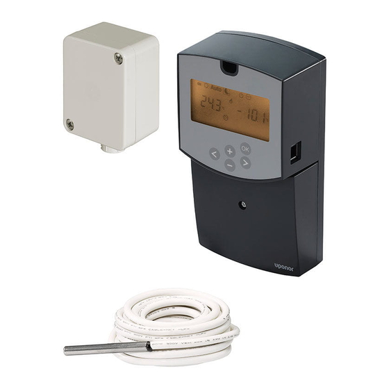
Page 45: Register A Wired Outdoor Sensor
6.12 Register a wired outdoor sensor To register a wired outdoor sensor to the controller: 1. Press and hold the OK button on the controller for about 10 seconds to enter the system parameters menu. 2. The settings icon is displayed in the top left hand corner of the display, and the text Hot type, Cld 10 s type, or rEv type (depending of current operating... -
Page 46: Finishing Installation
Finishing installation Uponor Smatrix Move (wired) Uponor Smatrix Move (wireless) Make a complete check up of the installation: 1. Close the cover of the controller. 2. Set the controller to the defined operating settings. 3. Print and fill in the “Installation report” located at the end of the manual. -
Page 47: Operate The Uponor Smatrix Move Controller
Operate the Uponor Smatrix Move controller Principle of operation Controller layout Uponor Smatrix Move is used to control an underfloor The illustration below shows parts of the controller. heating and/or cooling system in a house. The controller calculates the supply temperature using the outdoor temperature and a heating curve. -
Page 48: Display Layout
Display layout Pos. Icon Description Temperature The figure below shows all possible symbols and characters that can be shown on the display: Relative humidity H I J K L Digital clock Auto Parameter name in settings menu 1 2 3 4 5 6 7 Indicator showing AM or PM when the thermostat is set to 12 h mode 24 hour mode (no symbol shown) -
Page 49: Run Mode
Run mode Supply temperature The supply temperature in the system is calculated Press any button to light up the display and to show using system settings, sensors and thermostats, if the current run mode. In run mode different operating available. modes can be selected, as well as setting current time and day, and selecting a scheduling program. - Page 50 oliday mode omfort mode In this mode, a time period of 1 hour up to 44 days can In this mode the system will run in constant Comfort be set for when away on holiday. mode. To exit Comfort mode, use buttons < or > to change operating mode.
- Page 51 Change offset temperature when in another utomatiC mode operating mode: In this mode, the system switches automatically between Comfort and ECO mode using the preset 1. Use buttons < or > to move the marker to the or user defined scheduling programs available in the Comfort mode symbol .
- Page 52 To set time and day: To select a scheduling program: 1. Press the > button repeatedly until the clock symbol 1. Press the > button repeatedly until the scheduling is marked in the display. A digital clock and the program symbol is marked in the display.
- Page 53 Change ECO setback temperature when in another mode operating mode: In this mode the system will run in constant ECO mode. To exit ECO mode, use buttons < or > to change 1. Use buttons < or > to move the marker to the operating mode.
- Page 54 top mode Cheduling programS In this mode the software version is shown for about In this menu one of thirteen different scheduling 5 seconds, before everything in the display, except the programs can be selected for operating the system while Stop mode symbol is switched off.
- Page 55 Program P4: Program P7: Program P5: Program P8: Program P6: Program P9 U P O N O R S M AT R I X M O V E · I N S TA L L AT I O N A N D O P E R AT I O N M A N U A L...
- Page 56 User defined programs 6. Use buttons - or + to program the marked hour. Each press of the button confirms the change and To edit one of the available user defined scheduling moves the marker to the next hour. programs using single day programming: Comfort mode 1.
-
Page 57: System Parameter Settings
System parameter settings Menu Display Description Thermostat selection (installed/ In this menu, settings regarding the operation of the wireless/etc, see the registration controller is set. instruction on pages 41 – 42) N O T E ! tHty Not used by Move Some system parameter settings are only BGAP Boost function if the difference... - Page 58 0 – t 1 – h ype of inStallation eating Curve Select whether the installation is a heating and/or Set the heating curve of the system. cooling system. The heating curve is used to calculate the supply temperature to the heating system, while in heating N O T E ! mode.
- Page 59 2 – m 1 – C aximum Supply temperature ooling Curve heating Set the cooling curve of the system. Set a maximum supply temperature limitation, while in The cooling curve is used to calculate the supply heating mode. temperature to the cooling system, while in cooling mode.
- Page 60 2 – m 4 – t aximum Supply temperature ype of SyStem Cooling Select the type of hydraulic installation used in the Set a maximum supply temperature limitation, while in system. cooling mode. To change this setting: To change this setting: 1.
- Page 61 Do not attempt to connect Uponor Smatrix If the difference between the supply and return Base thermostats to the controller. They are temperature is higher than the set value, the function not suited for each other, and they may get activates.
- Page 62 8 – W 9 – W ireleSS thermoStat Configuration ireleSS thermoStat Configuration This parameter is only available if parameter 5 – This parameter is only available if parameter 5 – Thermostat selection is set to rF. Thermostat selection is set to rF, and parameter 4 – Type of system is set to 2P.1 or 2P.2.
- Page 63 10 – S To change this setting: upply temperature CompenSation 1. Use buttons - or + to change the parameter. Default: 0.1 ˚C Setting range: 0.1 – 9.9 ˚C, 0.1 ˚C increments 2. Press OK to confirm the change and return to the system parameter settings.
- Page 64 YES. N O T E ! Aqu An immersion thermostat/aquastat is If the Move system is integrated to an Uponor connected. If the thermostat setpoint is Smatrix Wave system (requires antenna A-155 reached (contact open), circulation pump 1 is...
- Page 65 YES, and parameter 4 – Type of system N O T E ! is set to 2P.1 or 2P.2. If the Move system is integrated to an Uponor Aqu An immersion thermostat/aquastat is Smatrix Wave system (requires antenna A-155 connected.
- Page 66 13 – o 15 – W utdoor SenSor SeleCtion ireleSS outdoor SenSor Configuration Select if an outdoor temperature sensor is used in the This parameter is only available if parameter 13 – Outdoor sensor selection is set to rF. system, and how it is connected. Register a wireless thermostat to the controller.
- Page 67 16 – d 18 – v iSplay unit alve and pump exerCiSe Select the temperature display unit used by the Select if the valve and pump exercise function is active. controller. The function is activated at noon (12:00) if the valve and pump has not been operated for a period of To change this setting: 24 hours.
- Page 68 20 – f To change this setting: orCed Control 1. Use buttons - or + to change the parameter. 0dry (Default) The function is not active. 7dry The function is active. 2. Press OK to confirm the change and return to the system parameter settings.
- Page 69 22 – f To stop the drying program: loor Creed drying program 1. Locate the parameter in the system parameter settings menu. 2. Press the OK button twice until 0 dry is displayed. 3. Press OK to confirm the change and return to the system parameter settings.
-
Page 70: Operate Uponor Smatrix Wave Analogue Thermostats
Two types of thermostats, both analogue and digital, Adjust temperature can be used in an Uponor Smatrix Move system. The temperature is changed by adjusting the setpoint on the thermostat to a value between 5 and 35 ˚C. aution... -
Page 71: Replace Batteries
Replace batteries Factory reset Replace the batteries of the thermostat when the LED Factory reset sets all parameter values to default flashes twice during a heating or cooling demand. settings. The thermostat will perform a self test, for about N O T E ! 10 seconds, when the batteries have been inserted. -
Page 72: Operate Uponor Smatrix Wave Digital Thermostats
Two types of thermostats, both analogue and digital, t-166 t-168 hermoStatS can be used in an Uponor Smatrix Move system. The illustration below shows the parts of the thermostat. The digital thermostats have a display relaying information to the user and buttons for control. -
Page 73: Display Layout
10.2 Display layout Change setpoint t-169 hermoStat The figures shows different display screens and the different symbols that can be shown. Run mode (default screen) Pos. Icon Description Change setpoint mode Temperature setpoint, using a - or + sign, two digital characters, a decimal point and a character showing either Pos. - Page 74 Alarms Control mode Pos. Icon Description Pos. Icon Description Alarm mode Current control mode Faulty indoor temperature sensor Indoor temperature indicator Current control mode Faulty floor temperature sensor Indoor temperature with floor temperature limitation indicator Current control mode Faulty remote temperature sensor Remote sensor temperature indicator Current control mode Faulty outdoor temperature sensor...
- Page 75 elative humidity Pos. Icon Description T-166 only Message field using three alphanumerical characters T-166 Temperature reading using a - or + sign, two digital characters, a decimal point T-168 and a character showing either 0 or 5 Pos. Icon Description Relative humidity level T-168 Relative humidity reading using two...
-
Page 76: Operating Buttons
10.3 Operating buttons Pos. Icon Description The figure below shows buttons used to operate the T-168 only digital thermostats. Digital clock T-169 T-168 only Parameter name in settings menu T-168 only Indicator showing AM or PM when the thermostat is set to 12 h mode No indication when the thermostat is set to 24 h mode T-168 only... -
Page 77: Start Up
10.4 Start up (t-168 et time and date only When starting the thermostat for the first time, after a When starting up, the software version is shown in the factory reset, or after it has been left without batteries display for about three seconds. Then the thermostat too long, the software requires the time and date to be enters run mode. -
Page 78: Adjust Temperature
5. Set day of the month. 10.5 Adjust temperature The temperature is changed by adjusting the setpoint on the thermostat. Use the buttons on the thermostat to adjust the temperature. The display will light up when pressing a button. It shuts off after about 10 seconds of inactivity. 6. -
Page 79: Run Mode
10.6 Run mode rt, r oom temperature mode 1. Room temperature (default) During normal operation the thermostat is in run mode. 2. Alarm list (only shown if an alarm is present in a While in run mode the display shows specific control T-169 thermostat) mode information. -
Page 80: Change Control Mode
10.8 Change control mode 10.9 Settings If an external sensor is connected to the thermostat, a In this menu all settings regarding the operation of the control mode must be chosen to accommodate the extra thermostat is set. functionality of the sensor. N O T E ! N O T E ! If no button is pressed for about 8 seconds,... - Page 81 00 p (t-168 Program P4: rogram only In this menu, one of seven different scheduling programs for Comfort/ECO mode can be set. Program 1 to 6 is pre-programmed and the 7th is user defined. The scheduled programs show the day split into 30 minute intervals which is set to either Comfort (black marker) or ECO mode (blank marker).
- Page 82 Customise user defined program for a single day Customise user defined program for a full week To customise the user defined program: NOTE! This method resets the current user defined program to factory defaults. 1. Press OK to enter parameter edit mode. To customise the user defined program: 2.
- Page 83 02 h 04 C eating Cooling Changeover ontrol mode In this menu it is manually set whether the system is In this menu, control mode for the thermostat is set. in heating, cooling or slave mode. In slave mode, an If an external sensor is connected to the thermostat, a external signal decides when to switch to cooling.
- Page 84 05 h 06 l igh floor temperature limitation oW floor temperature limitation In this menu a limit on the maximum allowable floor In this menu a limit on the minimum allowable floor temperature is set. Limitations does not affect the temperature is set.
- Page 85 08 d 10 t (t-168 iSplay unit ime and date only In this menu temperature display unit is set. In this menu time and date is set. This setting is required to utilise scheduling programs for this thermostat. To change this setting: Use buttons - or + to change the value.
-
Page 86: Replace Batteries
10.10 Replace batteries 10.11 Factory reset Factory reset sets all parameter values to default t-166 t-168 hermoStatS settings. Replace the batteries of the thermostat when the low battery icon is shown in the display. N O T E ! Do not factory reset the thermostat if not The illustration below shows how to change batteries. -
Page 87: Maintenance
11 Maintenance The maintenance of Uponor Smatrix Move includes the following: • Manual preventive maintenance • Automatic preventive maintenance • Corrective maintenance 11.1 Manual preventive maintenance Uponor Smatrix Move requires no preventive maintenance except cleaning: 1. Use a dry soft cloth to clean the components. -
Page 88: Troubleshooting
12 Troubleshooting The table below shows problems and alarms that can occur with Uponor Smatrix Move and describes solutions. A common cause of a problem though may be due to wrongly installed loops or mixed up thermostats. Alarms are indicated by a flashing display and error messages on the display. -
Page 89: Troubleshooting After Installation
12.1 Troubleshooting after installation Probable cause Problem Indication Solutions The system does The display is not illuminated There is no AC power to the controller 1. Check that the controller is connected not start to AC power 2. Check the wiring in the 230 V compartment 3. -
Page 90: Digital Thermostats T-166, T-168 And T-169, Alarms/Problems
12.2 Digital thermostats T-166, T-168 and T-169, alarms/problems An alarm is sent when more than 1 hour have elapsed since the controller received the last radio signal from the thermostat. The table below shows problems that can occur in the digital thermostats T-166 and T-168. Probable cause Indication Solutions... -
Page 91: Analogue Thermostat T-163, Alarms/Problems
The table below shows problems that can occur in the digital thermostat T-169. Indication Probable cause Solutions Alarm icon is displayed An error has occured Go to the alarm list for more information Battery icon is displayed in the alarm Thermostat battery power is running low Replace the battery list... -
Page 92: Contact Installer
12.5 Contact installer For installer contact information, see the installation report in the end of this document. Prepare the following information before contacting an installer: • Installation report • Drawings of the underfloor heating system (if available) • List of all alarms, including time and date 12.6 Installer instructions To determine if a problem is caused by the supply system or the control system, loosen the actuators... -
Page 93: Technical Data
13 Technical data 13.1 Technical data General IP30 (IP: degree of inaccessibility to active parts of the product and degree of water) Max. ambient RH (relative humidity) 85% at 20 °C Thermostat (requires antenna A-155) CE marking Low voltage tests EN 60730-1* and EN 60730-2-9*** EMC (electromagnetic compatibility requirements) tests EN 60730-1 and EN 301-489-3... -
Page 94: Technical Specifications
Controller CE marking VII (with thermostat) / III Low voltage tests EN 60730-1* and EN 60730-2-1** EMC (electromagnetic compatibility requirements) tests EN 60730-1 and EN 301-489-3* ERM (electromagnetic compatibility and radio spectrum matters) tests EN 300 220-3* Power supply 230 V AC +10/-15%, 50 Hz Operating temperature 0 °C to +50 °C Storage temperature... -
Page 95: Controller Layout
13.3 Controller layout Item Description Display Buttons Terminal block, earth Terminal block, circulation pump, mixing circuit 1 Terminal block, power supply Terminal block, cooling output or various applications Terminal block, heating output Terminal block, optional temperature limiter Fitted from the factory with a cable bridge, which must be removed before connecting a temperature limiter Terminal block, valve actuator Terminal block, outdoor sensor Terminal block, return temperature sensor... -
Page 96: Controller Wiring Diagram
13.4 Controller wiring diagram PUMP P1 ACTUATOR 230 V SENSORS POWER 230 V AC 230 V 50 Hz 50 Hz OUTSIDE * WATER RETURN ***** 230 V 50 Hz 230 V 50 Hz 230 V 50 Hz WATER IN In1/In2 *** In1/In2 *** In1/In2 ** PUMP P2 **... -
Page 97: Dimensions
13.6 Dimensions hermoStatS 80 mm T-169 ontroller 38 mm 9 mm 53 mm 51 mm 86 mm 30 mm 43 mm 80 mm T-166 60 mm 26,5 mm T-168 a-155 ontroller antenna 23 mm 80 mm T-163 60 mm 26,5 mm U P O N O R S M AT R I X M O V E ·... -
Page 98: Installation Report
Outdoor sensor Floor sensor Remote sensor Circulation pump 1 Actuator Circulation pump 2 (optional) 24 V Integration** with Uponor Actuator Smatrix Wave system Room name Wired Input 1 Wired Input 2 Requires antenna A-155 **) Requires antenna A-155 and a wireless thermostat... - Page 99 U P O N O R S M AT R I X M O V E · I N S TA L L AT I O N A N D O P E R AT I O N M A N U A L...
- Page 100 Uponor Corporation www.uponor.com Uponor reserves the right to make changes, without prior notification, to the specification of incorporated components in line with its policy of continuous improvement and development.
Need help?
Do you have a question about the Smatrix Move and is the answer not in the manual?
Questions and answers