Table of Contents
Advertisement
Quick Links
Advertisement
Table of Contents

Related Manuals for Snap-On Solus


Summary of Contents for Snap-On Solus
- Page 1 User Manual August 2009 EAZ0007E76F Rev. A...
- Page 2 Disclaimer The information, specifications and illustrations in this manual are based on the latest information available at the time of printing. Snap-on reserves the right to make changes at any time without notice. Visit our website at: www.snapon.com/solus (North America) snapondiag.com (Europe)
-
Page 3: Safety Information
Safety Information For your own safety and the safety of others, and to prevent damage to the equipment and vehicles upon which it is used, it is important that the accompanying Safety Information be read and understood by all persons operating, or coming into contact with, the equipment. We suggest you store a copy near the unit in sight of the operator. - Page 4 Safety Information Important Safety Instructions Safety messages contain three different type styles. • Normal type states the hazard. Bold type states how to avoid the hazard. • Italic type states the possible consequences of not avoiding the hazard. • An icon, when present, gives a graphical description of the potential hazard. Example: WARNING Risk of unexpected vehicle movement.
-
Page 5: Table Of Contents
Table of Contents Safety Information ........................iii Table of Contents ........................v Chapter 1: Using This Manual ....................1 Conventions..........................1 Bold Text ..........................1 Symbols ..........................1 Terminology ........................... 2 Notes and Important Messages ..................... 2 Procedures..........................2 Additional Manuals ........................3 Tool Help ............................ -
Page 6: Table Of Contents
Table of Contents Setting Up to Print ........................16 Connecting to a Computer......................17 Powering Off the Unit ......................... 17 Adjusting Brightness and Contrast ..................... 18 Chapter 4: Navigation ......................19 Screen Layout ..........................19 Upper Toolbar ........................20 Buffer Bar ..........................21 Main Body .......................... - Page 7 When I first turn on the scan tool, why does it beep but nothing appears on-screen? ....66 Can I use my other Snap-on® test adapters with this scan tool?..........66 Why do my batteries drain so quickly? ..................66 What should I do if my printer is not responding? ..............
-
Page 8: Chapter 1 Using This Manual
Using This Manual Chapter 1 This manual contains tool usage instructions. Some of the illustrations shown in this manual may contain modules and optional equipment that are not included on your system. Contact your sales representative for availability of other modules and optional equipment. -
Page 9: Terminology
Using This Manual Conventions 1.1.3 Terminology The term “select” means highlighting a button or menu item using the Thumb Pad and pressing the Y/a button to confirm the selection. Example: Select Reset. • The above statement abbreviates the following procedure: 1. -
Page 10: Additional Manuals
Using This Manual Additional Manuals 1.2 Additional Manuals This tool works in conjunction with other software products, which have their own manuals. See the appropriate manual for information regarding these products. 1.3 Tool Help Tool Help, which contains reference and procedural information found in this manual, is available on the scan tool. -
Page 11: Chapter 2 Introduction
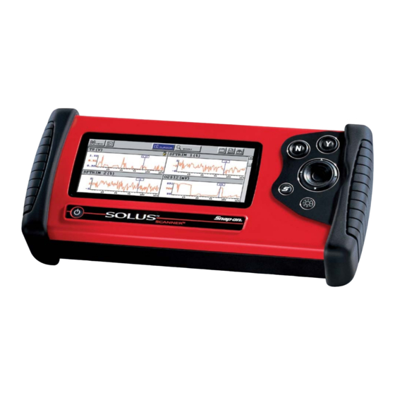
Introduction Chapter 2 ® The SOLUS™ scan tool uses Vehicle Communication Software and Fast Track Troubleshooter software to provide vehicle-specific trouble codes for various vehicle control systems such as engine, transmission, antilock brake system (ABS) and more, selected functional tests, and troubleshooting information. - Page 12 Introduction Functional Description 1— Liquid Crystal Display (LCD) 2— N/X (No) and Y/a (Yes) buttons 3— Thumb Pad 4— Right handgrip 5— Brightness/Contrast button 6— S button 7— Power button 8— Left handgrip Figure 2-2 Front view 1— DC power supply input 2—...
-
Page 13: Technical Specifications
Introduction Technical Specifications 1— Stand 2— Casing hook Figure 2-4 Back view 2.2 Technical Specifications Display: Liquid Crystal Display (LCD) 640 x 240 resolution 256 colors 6.2 inches (157.5 mm) CompactFlash ® Card Slot: Slot 1 is for the system CF card Slot 2 is for the data storage CF card IMPORTANT: Never remove the master storage CF card while the unit is turned on. -
Page 14: The Stand
Introduction The Stand Weight: 2.5 lbs 1,134 g Operating Temperature Range: 14 to 104°F -10 to 40°C Storage Temperature Range: -4 to 149°F -20 to 65°C Batteries: (6) 1.5V AA 2.3 The Stand The scan tool has a built-in, metal stand attached to the back. When the stand is not in use, it is secured to the back of the unit by an integrated casing hook (Figure 2-4 on page 6). -
Page 15: Control Buttons
Introduction Control Buttons Figure 2-6 Stand in hanging position 2.4 Control Buttons This scan tool has the following control buttons (Figure 2-2 on page 5): No (N/X) button • Yes (Y/a) button • Thumb Pad • • Brightness/Contrast button • S button •... -
Page 16: Thumb Pad
Introduction Connections 2.4.3 Thumb Pad The Thumb Pad moves the highlight, allowing vertical and horizontal on-screen movement. The Thumb Pad is typically used in combination with the Y/a and N/X buttons. 2.4.4 Brightness/Contrast Button The Brightness/Contrast button opens the dialog box that allows you to adjust the screen for optimum viewing. -
Page 17: Ir Output
Introduction Power Supply 2.5.3 IR Output The IR output is for printing data. For related information, see the following sections: • “Setting Up to Print” on page 16 • “Printing” on page 51 2.5.4 Data Cable Connector The connector on the data cable fits to adapters that connect the scan tool to a vehicle for testing. For related information, see the following sections: •... -
Page 18: Ac/Dc Power Supply
Introduction Cables • “Installing the Batteries” on page 14 “Power Management” on page 55 • “Replacing the Batteries” on page 64 • 2.6.3 AC/DC Power Supply This scan tool can be powered from a wall socket using the optional AC/DC power supply (Figure 2-7). -
Page 19: Auxiliary Power Cables
Introduction Cables An optional data cable extension is available. Refer to the Accessory Guide, included with your kit, for a complete listing of accessories and replacement parts. 2.7.2 Auxiliary Power Cables Two auxiliary power cables, the Lighter Power Cable (Figure 2-9) and the Battery Power Cable (Figure 2-10), are included with your scan tool and used for vehicles without battery power on the diagnostic connector. -
Page 20: Chapter 3 Getting Started
Getting Started Chapter 3 The following steps get you started using the scan tool: 1. Familiarize yourself with SOLUS controls and connections. Refer to “Control Buttons” on page 8 for details 2. Supply power to the scan tool 3. Press the Power button to turn the scan tool on 3.1 Supplying Power... -
Page 21: Connecting To Vehicle Power
Getting Started Connecting to Vehicle Power 8. To exit the demonstration, press N/X to return to the Main Menu OBD. 9. Highlight End of Diagnose and press Y/a 10. To return to the Main Menu, highlight the View button on the upper toolbar and press N/X. 3.3 Connecting to Vehicle Power You need the following to connect the scan tool unit to vehicle power: •... - Page 22 Getting Started Installing the Batteries • “Battery Power” on page 10 “Power Management” on page 55 • “Replacing the Batteries” on page 64 • IMPORTANT: Your scan tool will be damaged if the battery polarity is incorrect. Refer to the diagram on the rear cover of the scan tool for correct battery polarity.
-
Page 23: Connecting An Ac/Dc Power Supply
Getting Started Connecting an AC/DC Power Supply • Use batteries from a reputable manufacturer only. • When replacing batteries, always replace the whole set. • Do not use different brands of batteries together. • Do not try to recharge batteries that are not specifically designed to be recharged. •... -
Page 24: Connecting To A Computer
Getting Started Connecting to a Computer Before you can use the PRINT button in the upper toolbar, you must do the following: 1. Set up the printer. 2. Configure the scan tool to print. To set up the printer: Refer to your printer’s documentation for powering and paper loading instructions. •... -
Page 25: Adjusting Brightness And Contrast
Getting Started Adjusting Brightness and Contrast 3.10 Adjusting Brightness and Contrast The Brightness/Contrast button(Figure 3-5) lets you to adjust the screen for optimum viewing. Figure 3-5 Set Brightness/Contrast dialog box 1— Brightness slider control 2— Contrast slider control To adjust screen brightness and contrast: 1. -
Page 26: Chapter 4 Navigation
Navigation Chapter 4 The following sections provide general scan tool navigation information. 4.1 Screen Layout Scan tool screens (Figure 4-1) may include the following sections: The upper toolbar contains test controls. • The buffer bar shows how much data is stored in the scan tool memory •... -
Page 27: Upper Toolbar
Navigation Screen Layout 4.1.1 Upper Toolbar The upper toolbar (Figure 4-3 and Figure 4-4) controls vary depending on the mode and stage of operations (Table 4-1). Figure 4-3 Sample upper toolbar—Text view Figure 4-4 Sample upper toolbar—Graph view Table 4-1 Upper toolbar controls Name Button... -
Page 28: Buffer Bar
Navigation Screen Layout Scanner Button When the Scanner button is selected, the background of the main body turns white, indicating that the Text view is active (Figure 4-5). The up b and down d arrows and the Y/a and N/X buttons are used for screen navigation. -
Page 29: Main Body
Navigation Making Selections 4.1.3 Main Body The main body (Figure 4-8) of the screen provides prompts. The prompts guide you through vehicle identification and task selection. Once communication is established with an ECM, parameter information can be displayed. Figure 4-8 Sample Scanner main body in text view 4.1.4 LED Indicators Four LED indicators appear at the bottom of the screen and show designated operating... -
Page 30: Screen Messages
Navigation Screen Messages The right c arrow works like the Y/a button to confirm the selection of menu items. • The left e arrow works like the N/X button for cancelling, exiting, and closing menus. • See “Easy Scroll” on page 62 for information on activating Easy Scroll. 4.4 Screen Messages There are three types of on-screen messages: •... -
Page 31: Chapter 5: Operations
See “Connecting to a Vehicle” on page 26. 5. Select the required test from the menu—Select tests for the vehicle you have identified. See “Selecting from the System Main Menu” on page 27. Power up SOLUS (use internal battery power) Highlight the SCANNER button... -
Page 32: Selecting The Manufacturer
Operations Selecting the Manufacturer 5.1 Selecting the Manufacturer Vehicle manufacturers are organized into categories: Previous Vehicles—for recently tested vehicles • EOBD—for any EOBD vehicle • • OBD Health Check—for any OBD-II/EOBD vehicle • An alphabetical list of manufacturer 1— Scanner function 2—... -
Page 33: Selecting A System
Operations Selecting a System To identify a vehicle: 1. Once the database loads, the first vehicle identification (ID) screen displays (Figure 5-3). Figure 5-3 Sample Vehicle ID screen 2. Press the up b and down d arrows on the Thumb Pad until the correct choice is shown, then press Y/a. -
Page 34: Selecting From The System Main Menu
Operations Selecting from the System Main Menu Figure 5-5 Sample connection instruction screen Follow the on-screen connection instructions, then press Y/a to open the system Main Menu. 5.5 Selecting from the System Main Menu Depending on the vehicle, a number of options may be available on the system main menu (Figure 5-6). -
Page 35: Codes Menu
Operations Using the Scanner Functions • Vehicle data displays. A submenu displays when more than one data viewing mode is available on the identified vehicle (Figure 5-7). Figure 5-7 Sample data submenu On some models, the engine must be started or cranked before data can be displayed. For these models, a “Waiting to Communicate”... - Page 36 Operations Using the Scanner Functions Clear Codes The scan tool clears trouble codes from the control module memory on some vehicles. If this function is not available on the test vehicle, Clear Codes does not appear as a menu option. Freeze Frame/Failure Records This selection displays the DTC that was set, along with corresponding data, when the ECM commanded the malfunction indicator lamp (MIL) to turn on.
-
Page 37: Functional Tests
Operations Using the Scanner Functions Figure 5-10 Sample DTC Status screen 10. Press N/X to return to the DTC status entry screen. 11. Press N/X again to return to the Codes menu. 5.6.3 Functional Tests The Functional Tests selection is used to access vehicle-specific subsystem and component tests. -
Page 38: Terminating Vehicle Communication
Operations Terminating Vehicle Communication Select a system and a Troubleshooter Menu similar to Figure 5-12 displays. Figure 5-12 Sample Troubleshooter Menu ® Troubleshooter menus vary by make, model, and system. Refer to the Fast-Track Troubleshooter Quick Reference Guide for information. 5.7 Terminating Vehicle Communication Once you have established communication with a vehicle, you must terminate communication with the vehicle control module in order to safely shut down the scan tool. -
Page 39: Exiting Scanner Mode
Operations Viewing Data Graphically Figure 5-14 Sample Legacy Software main menu 3. When prompted to confirm your selection, press Y/a. 4. GM only: Select ABS (Exit & Re-ID). 5.7.1 Exiting Scanner Mode Exit Scanner mode before powering off. The exit procedure differs depending on the view option. IMPORTANT: Exiting Scanner mode does not ensure that you have safely terminated communication with a vehicle. -
Page 40: Changing Screen Views
Operations Viewing Data Graphically 5.8.1 Changing Screen Views Data can be viewed in the following formats: – Listed by PID – Text view Graph view – To change screen views: 1. Select the View button. A drop-down menu displays (Figure 5-15). 2. - Page 41 Operations Viewing Data Graphically 3— PID data 4— Buffer bar indicator Figure 5-17 Sample paused upper toolbar in PID View To review collected PID data: 1. Select the Pause button to stop the data collection. 2. Select the Review button and use the right c and left e arrows to scroll through the data stored in the buffer.
- Page 42 Operations Viewing Data Graphically Figure 5-19 Sample locked PID 4. Repeat the above steps to lock multiple parameters. 5. Press N/X to return to the upper toolbar. To unlock parameters: • Select a locked parameter and select Unlock when the parameter menu displays. The lock icon disappears and the parameter can be scrolled as before.
- Page 43 Operations Viewing Data Graphically 1— Maximum value of captured data 2— Current value 3— Minimum value of captured data Figure 5-21 Sample graph screen Parameter Menu In Graph view, the scan tool offers a parameter menu (Figure 5-22) with the following options: Lock—locks the selected parameter into position to compare readings.
- Page 44 Operations Viewing Data Graphically Figure 5-23 Lock icon indicating a locked parameter 4. Scroll other parameters into place to compare readings. To unlock a parameter: 1. Select the locked parameter. The parameter menu displays. 2. Select Unlock. The lock icon disappears and the parameter can be scrolled as before. To unlock all parameters: 1.
- Page 45 Operations Viewing Data Graphically Figure 5-24 Sample manually scaling a parameter 3. Use the down d arrow to move the maximum displayed value into position. 4. Press Y/a to set the selected value. 5. Press Y/a to scale the minimum value. 6.
- Page 46 Operations Viewing Data Graphically 4. Press Y/a to set the trigger. When set, the solid black line changes to a dotted line and the position value no longer displays (Figure 5-26). 1— Upper trigger level 2— Lower trigger level Figure 5-26 Sample set trigger levels 5.
- Page 47 Operations Viewing Data Graphically Figure 5-28 Sample collecting snapshot dialog box The amount of data collected is specified by the % After Trigger setting, found in Utilities > Tool Setup > Save Data. You can manually stop the snapshot by pressing Y/a at any time during the data collection.
-
Page 48: Pausing Data
Operations Viewing Data Graphically The check mark next to the menu option disappears. 5.8.2 Pausing Data The Pause button temporarily stops, or “pauses”, data collection when viewing parameter data in the PID List or Graphs views (Figure 5-31). Figure 5-31 Pause button viewing “live-screen”... -
Page 49: Clearing The Data Buffer
Operations Viewing Data Graphically – Auto Scroll Fast—automatically advances data in a continuous loop at normal speed. This is the recording speed, which is the transmission speed of the ECM. – Auto Scroll Slow—automatically advances data in a continuous loop at half speed. 4. -
Page 50: Using Zoom
Operations Viewing Data Graphically To use the Cursor: 1. Select the Pause button. 2. Select the Cursor button. Cursor lines display (Figure 5-36). The value where the cursor line intersects the data displays above the cursor line. Figure 5-36 Sample cursors on paused data 3. -
Page 51: Saving Captured Data
Operations Saving Captured Data 5.9 Saving Captured Data The scan tool provides multiple options for saving and reviewing captured data: Save Movie—This feature allows you to save up to 2000 frames of data (buffered data plus • data transmitted after triggering) for each available parameter. Files can be saved from the Text, PID, and Graph views, but can only be replayed in the Graph view. - Page 52 Operations Saving Captured Data Figure 5-42 Data Management menu option A list of all saved files displays. 3. Select the file that you would like to review (Figure 5-43). Figure 5-43 Sample saved data list NOTE: Movie files are saved with a SC(M) file type designation. 4.
-
Page 53: Viewing Saved Data
Operations Viewing Saved Data NOTE: Frame files are saved with a SC(S) file type designation. To save an image file: 1. Select the Save button from the toolbar. A drop-down menu displays (Figure 5-40). 2. Select Save Image from the drop-down menu. The Saving screen image... -
Page 54: Identifying Saved Files
Operations Viewing Saved Data 3— CF Slot indicators Displays which CF Slot is selected in Setup. The left icon is CF Slot 2 and the right icon is CF Slot 1. The CF Slot 2 icon will be crossed out if there is no card in the slot when CF Slot 2 is the selected destination. -
Page 55: Loading Saved Files
Operations Viewing Saved Data 5.10.2 Loading Saved Files The Load button lets you review saved screen data and print the screen. To load data: 1. Select Saved Data > Data Management. The Data Management screen displays. 2. Select a file from the list. 3. -
Page 56: Deleting Saved Files
Operations Viewing Saved Data 5.10.5 Deleting Saved Files The Delete button lets you remove saved files from memory. NOTE: Factory-installed files cannot be deleted. To delete files: 1. Select Saved Data > Data Management. 2. Select a file from the list. 3. -
Page 57: Selecting All Files
Operations Viewing Saved Data 5.10.7 Selecting All Files Use the Select All button to highlight all files on-screen so you can delete, copy, or move the files as needed (Figure 5-47). Figure 5-47 Sample Select All screen 5.10.8 Viewing Saved Data Information Selecting the Info button on the toolbar opens a window that provides detailed information about the saved data files, such as the amount of storage memory used and the capacity of the memory storage media (Figure 5-48). -
Page 58: Printing
Operations Printing 2. Select the Setup button. The Save Data dialog box displays. 3. Select the My data field. 4. Select an option from the drop-down list. The drop-down list closes automatically. 5. Press N/X to close the Save Data dialog box. The checkbox for the CF slot you selected is checked (Figure 5-50). -
Page 59: Custom Setup
Operations Tools Button Figure 5-52 Sample Tools button menu The following choices are available on a dropdown menu: • Custom Setup • Save Data • Custom Data List • LED Setup NOTE: The Custom Data List and LED Setup selections are only available when in the Text view mode, these menu selections do not display when in Graph or PID List modes. -
Page 60: Save Data
Operations Tools Button 2. Use right c and left e arrows to move between measurements, press Y/a to open a dropdown menu for the item to be changed. 3. Select the desired measurement and the dropdown closes. 4. Press N/X to confirm your selections and return to the Tools Setup menu. 5.12.2 Save Data Selecting Save Data from the dropdown menu opens the Save Data dialog box, which allows you to select where and how data is saved. -
Page 61: Led Setup
Operations Utilities 5.12.4 LED Setup The LED Setup selection is used to program the operation of the four LEDs located just below the main body of the Scanner screen. The LEDs switch on and off to reflect a change of state for the assigned digital parameters. - Page 62 Operations Utilities Figure 5-57 Tool Setup sample menu The Tool Setup submenu includes the following options: • “Power Management” • “Scanner Units” • “Save Data” “Printer” • “Date” • “Time” • • “S Button” • “Color Theme” • “Scanner View” •...
- Page 63 Operations Utilities Scanner Units The Scanner Units selection is used to change the units of measurement. Choose between US Customary or metric units of measure for available data parameters. All measurement units return to their default values when the internal batteries are disconnected or different software is selected.
- Page 64 Operations Utilities Figure 5-60 Sample Save Data dialog box 2. Select from the drop-down lists as necessary: – % After Trigger determines how much new data is collected. At the default setting (30%), 30 percent of the saved file will be newly collected data and 70 percent will be retrieved from data stored in the buffer.
- Page 65 Operations Utilities Date Selecting Date lets you set the date that displays in the Saved Data properties. To set the date: 1. Select Utilities > Tool Setup > Date. The Date dialog box displays. 2. Select the Day, Month, Year, or Style field. A drop-down list displays (Figure 5-62).
- Page 66 Operations Utilities S Button Selecting S Button allows you to change the functionality of the S button. Possible function assignments include: • Save Image—is the default and takes a snapshot of the current screen. The snapshot is saved as either a bitmap or a jpeg image, which can be opened using standard Internet browsers or graphics applications.
- Page 67 Operations Utilities Figure 5-65 Color Theme Menu 3. Select a function from the drop-down list. 4. Press N/X to close the dialog box. Scanner View Scanner View sets the default setting for how the data displays. Scanner View options include: Text •...
-
Page 68: System Tools
Operations Utilities 5.13.2 System Tools The System Tools submenu (Figure 5-67) lets you perform system maintenance functions. Figure 5-67 Sample System Tools submenu System Tool options include: • Add Program—lets you add optional software. • Update Scanner Module—When instructed by a Help Desk representative to use, lets you update the Scanner module files. -
Page 69: Easy Scroll
5.13.6 Run ® The Run option is used to access special Snap-on CF card applications. To run special CF card applications: 1. Insert the CF card containing the special application into CF Slot 2 on the top of the unit (Figure 2-3 on page 5). - Page 70 Operations Utilities To display the system information: 1. Select Utilities > System Info. The System Information screen displays. The left field of the screen shows the information menu and the right field displays the selected information. Navigate the information screens as follows: a.
-
Page 71: Chapter 6 Maintenance
Maintenance Chapter 6 This section covers the following maintenance issues: Cleaning and damage inspection • Battery replacement • Storage tips • • Disposal requirements (environmental hazards) 6.1 Cleaning and Damage Inspection When using the scan tool, make sure to do the following: Before and after each use, check the housing, wiring, and connectors for dirt and damage. -
Page 72: Storage Tips
Maintenance Storage Tips 3. Observing proper polarity (shown on the back of the scan tool), install six AA batteries. IMPORTANT: Your scan tool will be damaged if the battery polarity is incorrect. Refer to the diagram on the rear cover of the scan tool for correct battery polarity. 4. -
Page 73: Appendix A Frequently Asked Questions
“When I first turn on the scan tool, why does it beep but nothing appears on-screen?” on • page 66 • “Can I use my other Snap-on® test adapters with this scan tool?” on page 66 • “Why do my batteries drain so quickly?” on page 66 •... -
Page 74: What Should I Do If My Printer Is Not Responding
Frequently Asked Questions What should I do if my printer is not responding? A.4 What should I do if my printer is not responding? It may take a minute or two before the printer receives the print request. If there is still no response after a few minutes, make sure the following conditions are met: The printer is receiving power and is turned on. -
Page 75: Appendix B Troubleshooting
Troubleshooting Appendix B This section addresses issues that may arise when using the scan tool. B.1 No Communication Message The screen displays a “No Communication” (Figure B-1) message when the scan tool and the vehicle control module cannot communicate with each other for some reason. Figure B-1 Sample No Communication message The following conditions will cause the scan tool to display a “No Communication”... -
Page 76: Emergency Restart
Troubleshooting Emergency Restart B.3 Emergency Restart If your scan tool freezes or will not power off, you can perform an emergency restart. To perform an emergency restart: 1. Remove the left handgrip. 2. Locate the emergency restart button on the back of the unit (Figure B-2). Figure B-2 Emergency restart button location 3. -
Page 77: Appendix C Downloading And Installing Software Updates
• • USB 2.0 or later • Internet Explorer 6.0 or higher • Internet connection • Adobe Reader software (free download at www.adobe.com/products/reader) A type A/B USB cable is also needed to connect the SOLUS scan tool to the PC. -
Page 78: Verifying Pc System Properties
Downloading and Installing Software Updates Verifying Minimum PC Requirements C.2.1 Verifying PC System Properties Follow the procedures below to check your PC system properties and to determine how much free space is available on your hard drive. To check your PC system properties: 1. -
Page 79: Downloading And Installing Shopstream Connect
Downloading and Installing Software Updates Downloading and Installing ShopStream Connect C.3 Downloading and Installing ShopStream Connect Follow the procedure below to download the ShopStream Connect software. To download the software: 1. From your PC, go to http://diagnostics.snapon.com/scc using your Internet browser. 2. - Page 80 Downloading and Installing Software Updates Downloading and Installing ShopStream Connect The Choose Destination Location screen displays. It is highly recommended to allow the software to install in the default location. 4. Select Next to continue. 5. Select Install when the Ready to Install the Program screen displays to begin the installation. The Setup Status screen tracks progress as the program installs (Figure C-5).
-
Page 81: Downloading Service Upgrades
3. From the SOLUS main menu, select Utilities > Connect to PC to place the scan tool in Connect to PC mode. 4. Connect the USB cable between the USB port on top of the SOLUS scan tool and a USB port on the PC. - Page 82 Figure C-9 Sample removable disk window 5. Double-click the desktop icon to launch ShopStream Connect (Figure C-7). 6. Once ShopStream Connect opens; select Tools > Update Software > SOLUS from the Menu bar (Figure C-10). Figure C-10 Sample Update Software menu When connectivity is established with the Snap-on Web server, a check for updates confirmation message displays (Figure C-11).
- Page 83 11. After SOLUS powers on, the upgrade installation begins. The install may take several minutes and a series of screens tracks the progress. Do not press any buttons or disrupt power during the installation. When the main menu displays, the installation is complete and your SOLUS scan tool is ready for use.
-
Page 84: Index
Index data cable 11 See also power supply AA batteries data cable connector 5 installing 15 data cable extension replacing 64 accessory 12 technical specifications 7 Data Display 27 time, date, and custom settings 10 data parameters AC power adapter 11 customizing list 53 adapters. - Page 85 Index infrared (IR) port Play button. See upper toolbar location 5 Power button. See buttons inspecting unit for damage 64 power cables. See auxiliary power cables installing batteries 14 Power Management 55 internal batteries. See AA batteries power options 17 power supply connecting to 13 –...
- Page 86 Index selecting tests 24 selecting the manufacturer 25 unit operations. See operations set trigger levels 38 – unlock all 36 ShopStream Connect 17 unlock all PIDs 37 shutting down the unit 9 unlock PIDS 37 software unlocking a parameter 35 exiting 31 upper toolbar selecting 24...
- Page 87 Index...
Need help?
Do you have a question about the Solus and is the answer not in the manual?
Questions and answers