
Related Manuals for RKI 65-2484RK


Summary of Contents for RKI 65-2484RK
- Page 1 65-2484RK Multi Point Detector Operator’s Manual Part Number: 71-0252RK Revision: P1 Released: 4/27/12 RKI Instruments, Inc. www.rkiinstruments.com...
- Page 2 Typical calibration frequencies for most applications are between 3 and 6 months, but can be required more often or less often based on your usage. 65-2484RK Multi Point Detector...
- Page 3 Product Warranty RKI Instruments, Inc. warrants gas alarm equipment sold by us to be free from defects in materials, workmanship, and performance for a period of one year from date of shipment from RKI Instruments, Inc. Any parts found defective within that period will be repaired or replaced, at our option, free of charge.
-
Page 4: Table Of Contents
Parts List ..............36 65-2484RK Multi Point Detector... -
Page 5: Overview
Overview This manual describes the 65-2484RK multi point direct connect detector. This manual also describes how to install, start up, maintain, and calibrate the detector when it is used with a gas monitoring controller. A parts list at the end of this manual lists replacement parts and accessories for the detector. - Page 6 65-2484RK-55: LEL (IR CH /CO/PH , methane calibration for LEL 65-2484RK-56: LEL (IR CH /CO/SO , methane calibration for LEL *Note: Since the 65-2484RK is a direct connect detector, the calibration is done at the controller. 2 • 65-2484RK Multi Point Detector...
- Page 7 WARNING: When using the 65-2484RK, you must follow the instructions and warnings in this manual to assure proper and safe operation of the 65-2484RK and to minimize the risk of personal injury. Be sure to maintain and periodically calibrate the 65-2484RK as described in this manual.
-
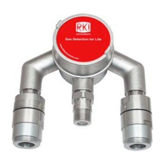
Page 8: Description
Four color- coded leads extend from the top of the detector. The leads allow you to connect the detector to the terminal block. 4 • 65-2484RK Multi Point Detector... - Page 9 (in case the replacement sensor label that is applied to one of the leads is lost), a short length of red shrink tubing is applied to the white wire of the propane detector near where the wire comes out of the nipple. 65-2484RK Multi Point Detector • 5...
- Page 10 The plug-in sensor is secured in the detector assembly by the housing cap. It has two pins that mate with the sockets in the detector housing body. Through a series of chemical and electrical reactions, the sensor produces an electrical output that corresponds to the detection range of the transmitter. 6 • 65-2484RK Multi Point Detector...
- Page 11 Through a series of chemical and electrical reactions, the sensor produces an electrical output that is proportional to the detection range of the detector. 65-2484RK Multi Point Detector • 7...
- Page 12 The disc-shaped charcoal filter is secured to the face of the CO sensor with a rubber boot. The charcoal filter prevents interference gases (hydrogen sulfide [H S] and certain hydrocarbons) from producing false CO readings. 8 • 65-2484RK Multi Point Detector...
-
Page 13: Conduit Seal
Conduit Seal The conduit seal isolates the volumes of the 2 junction boxes. 65-2484RK Multi Point Detector • 9... -
Page 14: Junction Box
Select a site where the detector is not likely to be bumped or disturbed. Make sure there is sufficient room to perform start-up, maintenance, and calibration procedures. • Select a site where the target gases are likely to be found first. 10 • 65-2484RK Multi Point Detector... - Page 15 Detector Sealed W ire Conduit ESM-01 3/4" NPT Nipple (2X) Detector LEL Detector Oxygen or C O 1.10 Detector Figure 7: Outline & Mounting Dimensions for Versions with Catalytic LEL Detector (65-2484RK-0X, 65-2484RK-2X, 65-2484RK-4X) 65-2484RK Multi Point Detector • 11...
- Page 16 At the mounting site you select, use #10 screws to mount the detector to a vertical surface. CAUTION: Mount the multi-point detector with the detectors facing down (see Figures 7-8). NOTE: If your application does not require a specific mounting site, mount the detector at approximately breathing level. 12 • 65-2484RK Multi Point Detector...
-
Page 17: Wiring The Multi-Point Detector To A Controller
Route the cable or wires leading from the multi-point detector through one of the conduit hubs at the controller housing. Use appropriate conduit fittings and construction technique for the environmental rating of the controller. RKI controllers are typically rated NEMA 4X. - Page 18 W HITE R ED W HITE GR EE N GR EE N B LAC K LEL D ET ECT OR OXYGEN D ETEC T OR Figure 9: Wiring for Catalytic LEL/O S/ESM-01 Versions (65-2484RK-0X) 14 • 65-2484RK Multi Point Detector...
- Page 19 W HIT E R ED W HITE GR EE N GR EE N B L AC K LEL D ET ECT OR OXYGEN D ETEC T OR Figure 10: Wiring for Catalytic LEL/O /CO/ESM-01 Versions (65-2484RK-4X) 65-2484RK Multi Point Detector • 15...
- Page 20 R ED R ED W HIT E B LAC K GR EE N B LAC K LEL D ET ECT OR CO D ETEC T OR Figure 11: Wiring for LEL/CO/H S/ESM-01 Versions (65-2484RK-2X) 16 • 65-2484RK Multi Point Detector...
- Page 21 R ED W HITE GR EE N GR EE N B LAC K I R L EL DE TEC TOR OXYGEN D ETEC T OR Figure 12: Wiring for IR LEL/O S/ESM-01 Versions (65-2484RK-1X) 65-2484RK Multi Point Detector • 17...
- Page 22 W HITE R ED W HITE GR EE N GR EE N B LAC K IR L EL DE TEC TOR OXYGEN D ETEC T OR Figure 13: Wiring for IR LEL/O /CO/ESM-01 Versions (65-2484RK-5X) 18 • 65-2484RK Multi Point Detector...
- Page 23 R ED W HITE B LAC K GR EE N B LAC K I R L EL DE TEC TOR CO D ETEC T OR Figure 14: Wiring for IR LEL/CO/H S/ESM-01 Versions (65-2484RK-3X) 65-2484RK Multi Point Detector • 19...
-
Page 24: Startup
Connect the cable’s drain wire to an available chassis ground at the controller. RKI controllers typically have a ground stud that can be used to ground the cable’s drain wire. Start Up This section describes procedures to start up the multi-point detector and place the detector into normal operation. -
Page 25: Maintenance
This procedure describes a test to verify that each detector in the multi-point detector responds properly to its target gas. It describes a test using a fixed flow regulator with an on/off knob. RKI Instruments, Inc. recommends using a 0.5 LPM (liters per minute) fixed flow regulator for the LEL, O S, or CO channels. - Page 26 When the controller display reading falls below the alarm setpoints, return the controller to normal operation. Store the components of the calibration kit in a safe place. Quarterly Calibrate the multi-point detector as described in the Calibration section of this manual. 22 • 65-2484RK Multi Point Detector...
-
Page 27: Troubleshooting
O S, CO, or ESM-01 plug-in months. sensor as described later in this Some applications section. may require a more 5. If the calibration/response difficulties frequent calibration continue, contact RKI for further schedule. instruction. 65-2484RK Multi Point Detector • 23... -
Page 28: Replacing Components Of The Multi-Point Detector
Unplug and remove the oxygen sensor. Carefully plug the replacement sensor into the socket pattern that is located in the detector housing. Make sure the cap gasket is in place and screw the detector housing cap back onto the 24 • 65-2484RK Multi Point Detector... - Page 29 If sensor electrolyte comes in contact with your skin, wash affected area thoroughly with soap and water. Turn off the controller. Turn off or unplug power to the controller. 65-2484RK Multi Point Detector • 25...
- Page 30 CAUTION: Allow the replacement detector to warm up for 5 minutes before you continue with the next step. 11. Calibrate the replacement detector as described in “Calibration, LEL, H S, and CO Detectors” on page 30. 26 • 65-2484RK Multi Point Detector...
- Page 31 10. Make sure the cap gasket is in place and screw the detector housing cap back onto the detector housing body. 11. Turn on or plug in power to the controller. 12. Turn on the controller and place into normal operation. 65-2484RK Multi Point Detector • 27...
- Page 32 Unscrew the detector housing cap with the splashguard from the detector housing body. Make sure not to lose the cap gasket. Unplug and remove the toxic sensor. Carefully plug the replacement sensor into the connector that is located in the detector housing body. 28 • 65-2484RK Multi Point Detector...
- Page 33 10. Turn on the controller. CAUTION: Allow the replacement detector to warm up for 5 minutes before you continue with the next step. 11. Calibrate the replacement detector as described in “Calibration, ESM-01 Toxic Detector” on page 33. 65-2484RK Multi Point Detector • 29...
-
Page 34: Calibration, Lel, Co, And H 2 S Detectors
81-1117RK calibration cup, calibration gas, sample tubing, and a fixed flow regulator with an on/off knob. RKI Instruments, Inc. recommends using a 0.5 LPM (liters per minute) fixed flow regulator. To properly calibrate the multi-point detector, you must calibrate each connected detector. -
Page 35: Setting The Zero Reading
NOTE: RKI controllers have a minimum hold feature for zero adjustment and a peak hold feature for span adjustment. Because of this, the instructions call for turning off the gas to a detector before making adjustments. -
Page 36: Calibration, Oxygen Detector
Put the controller into its calibration program. See the controller operator’s manual for instructions to enter the calibration program. NOTE: RKI controllers have a peak hold feature for fresh air adjustment and a minimum hold feature for zero adjustment. Because of this, the instructions call for turning off the gas to a detector before making adjustments. -
Page 37: Setting The Zero Reading
Required Detector Type Flowrate for Calibration Specified on Calibration Cup Calibration Cup Arsine (AsH 81-1138RK 81-1051RK, 0.5 LPM (liters per minute) Chlorine (Cl 81-1138RK-CL2 81-1051RK, 0.5 LPM Hydrogen Cyanide (HCN) 81-1138RK 81-1051RK, 0.5 LPM 65-2484RK Multi Point Detector • 33... -
Page 38: Preparing For Calibration
Put the controller into its calibration program. See the controller operator’s manual for instructions to enter the calibration program. NOTE: RKI controllers have a minimum hold feature for zero adjustment and a peak hold feature for span adjustment. Because of this, the instructions call for turning off the gas to a detector before making adjustments. -
Page 39: Setting The Response Reading
NOTE: If you do not allow the gas reading to decrease below the alarm points, then unwanted alarms may occur. Verify that the controller display reading decreases and stabilizes at 0 ppm. Store the components of the calibration kit in a safe and convenient place. 65-2484RK Multi Point Detector • 35... -
Page 40: Parts List
Multi-point detector assembly, LEL (IR CH S/Cl 65-2484RK-13 Multi-point detector assembly, LEL (IR CH S/HCN 65-2484RK-14 Multi-point detector assembly, LEL (IR CH S/NH 65-2484RK-15 Multi-point detector assembly, LEL (IR CH S/PH 65-2484RK-16 Multi-point detector assembly, LEL (IR CH S/SO 36 • 65-2484RK Multi Point Detector... - Page 41 Multi-point detector assembly, LEL (IR CH /CO/SO 65-2514RK Oxygen replacement detector assembly (includes sensor) 71-0252RK 65-2484RK Multi Point Detector Operator’s Manual (this document) 81-0004RK Calibration cylinder, 50% LEL propane in air, 17 liter steel 81-0004RK-01 Calibration cylinder, 50% LEL propane in air, 34 liter steel...
- Page 42 81-0192RK-02 Calibration cylinder, 2 ppm Cl in nitrogen, 58 liter, aluminum 81-0192RK-04 Calibration cylinder, 2 ppm Cl in nitrogen, 34 liter aluminum 81-0196RK-02 Calibration cylinder, 10 ppm HCN in nitrogen, 58 liter aluminum 38 • 65-2484RK Multi Point Detector...
- Page 43 ESM-01 plug-in sensor, 0 - 6.00 ppm sulphur dioxide, diffusion type only ESM-01DH-PH3 ESM-01 plug-in sensor, 0 - 1.00 ppm phosphine ESM-01R-D-NH3 ESM-01 plug-in sensor, 0 - 75.0 ppm ammonia, diffusion type only ESM-K01-D-CL2 ESM-01 plug-in sensor, 0 - 3.00 ppm chlorine, diffusion type only 65-2484RK Multi Point Detector • 39...
Need help?
Do you have a question about the 65-2484RK and is the answer not in the manual?
Questions and answers