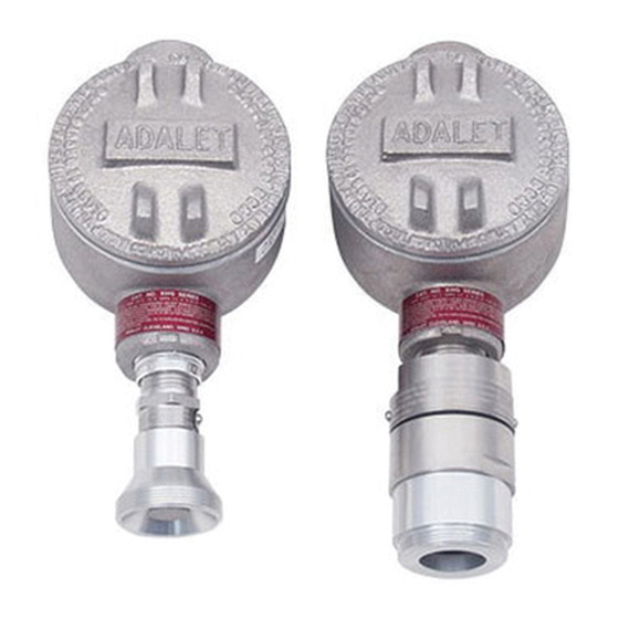
Summary of Contents for RKI 61-1004RK
- Page 1 61-1004RK/61-0191RK Detector Operator’s Manual Part Number: 71-0145RK Revision: A Released: 4/12/11 www.rkiinstruments.com...
- Page 2 Typical calibration frequencies for most applications are between 6 and 12 months, but can be required more often or less often based on your usage. 61-1004RK/61-0191RK Combustible Gas Detector...
- Page 3 Product Warranty RKI Instruments, Inc. warrants gas alarm equipment sold by us to be free from defects in materials, workmanship, and performance for a period of one year from date of shipment from RKI Instruments, Inc. Any parts found defective within that period will be repaired or replaced, at our option, free of charge.
-
Page 4: Table Of Contents
Parts List ..............13 61-1004RK/61-0191RK Combustible Gas Detector... -
Page 5: Overview
± 5% of reading or ± 2% of full scale (whichever is greater) WARNING: When using the 61-1004RK, you must follow the instructions and warnings in this manual to assure proper and safe operation of the 61-1004RK and to minimize the risk of personal injury. Be sure to maintain and periodically calibrate the 61-1004RK as described in this manual. -
Page 6: Description
61-1004RK-02 which has a detection range of 0 - 5,000 ppm, the 61-1004RK-03 which has a detection range of 0 - 5% volume, the 61-1004RK-05 which has a detection range of 0 - 50% volume, and the 61-1004RK-10 which has a detection range of 0 - 100% volume. -
Page 7: Junction Box
0 - 100% volume red shrink tubing on green wire The output of the CO detector mimics the output of RKI’s standard catalytic LEL detectors. For this reason, the CO detector’s wire colors are the same as RKI’s catalytic LEL detectors, black, white, green, and red. When the CO... -
Page 8: Installation
Junction 7.1 Max Spacer, 3X IR CO2 Detector Figure 2: Mounting the CO Detector At the mounting site you select, hang or mount the junction box with the detector facing down (see Figure 2). 4 • 61-1004RK/61-0191RK Combustible Gas Detector... -
Page 9: Wiring The Co 2 Detector To A Controller
As mentioned in “Description” on page 2, the IR CO detector wires to an RKI controller the same way as an RKI LEL detector, to the LEL detector terminals. See Figure 3 below for the wiring connections. Turn off the controller. - Page 10 Detector to a Controller 10. If using shielded cable, connect the cable’s drain wire to an available chassis ground at the controller. RKI controllers typically have a ground stud that is a convenient grounding location. 6 • 61-1004RK/61-0191RK Combustible Gas Detector...
-
Page 11: Startup
Remove the calibration cup from the detector. You may leave the sample tubing connected to the calibration cup for convenience. 10. Store the components of the calibration kit in a safe and convenient place. 61-1004RK/61-0191RK Combustible Gas Detector • 7... -
Page 12: Maintenance
Screw the regulator into the calibration cylinder. Turn the on/off knob on the regulator counterclockwise to open the regulator. Apply gas to the detector for one minute. Verify that the reading is within ± 20% of the gas concentration. 8 • 61-1004RK/61-0191RK Combustible Gas Detector... -
Page 13: Troubleshooting
4. If the calibration/response difficulties • Detector requires continue, contact RKI for further frequent calibration. instruction. Note: Under “normal” circumstances, the detector requires calibration once every six months. Some applications may require a more frequent calibration schedule. 61-1004RK/61-0191RK Combustible Gas Detector • 9... -
Page 14: Replacing The Co 2 Detector
(see Figure 3 on page 6). See the controller operator’s manual and the controller’s detector head specification sheet for the 61-1004RK detector to verify the connections to the controller are correct. -
Page 15: Calibration
1 minute. Turn the regulator’s on/off knob clockwise to close the regulator. 61-1004RK/61-0191RK Combustible Gas Detector • 11... -
Page 16: Returning To Normal Operation
The 0-50 %volume and 0-100 %volume detectors will not display a reading in fresh air because their ranges are too large. Store the components of the calibration kit in a safe and convenient place. 12 • 61-1004RK/61-0191RK Combustible Gas Detector... -
Page 17: Parts List
Parts List Table 3 lists replacement parts and accessories for the 61-1004RK and 61-0191RK CO detectors. Table 4: Parts List Part Number Description 18-0400RK-01 Junction box with spacers 61-0191RK-02 Infrared CO detector, 0 - 5,000 ppm 61-0191RK-03 Infrared CO detector, 0 - 5% Volume...


Need help?
Do you have a question about the 61-1004RK and is the answer not in the manual?
Questions and answers