Table of Contents
Advertisement
Advertisement
Table of Contents

Related Manuals for Mojo C-75


Summary of Contents for Mojo C-75
-
Page 1: Installation Guide
Installation Guide C-75 Access Point/Sensor... - Page 2 This page is intentionally left blank.
- Page 3 FOR COUNTRY CODE SELECTION USAGE (WLAN DEVICES) Note: The country code selection is for non-US models only and is not available to all US models. Per FCC regulations, all Wi-Fi products marketed in the US must be fixed to US operation channels only. C-75 Installation Guide...
- Page 4 Cet equipement est conforme aux limites d exposition aux rayonnements IC etablies pour un environnement non controle. Cet equipement doit @tre installe et utilise avec un minimum de 20 cm de distance entre la source de rayonnement et votre cmps. C-75 Installation Guide...
-
Page 5: About This Guide
About this Guide This installation guide explains how to mount the C-75 access point (AP) and the various configuration details. Important! Please read the EULA before installing the C-75. Installation constitutes your acceptance of the terms and conditions of the EULA. -
Page 6: Package Contents
Package Contents Please ensure that the items shown in Figure 1-1 are included in the C-75 device package: Figure 0-1 C-75 Package Contents Note: The MAC address of the device is printed on a label at the bottom of the product and the packaging box. - Page 7 Optional Cellular Activity Detection Device The cellular activity detection device is an optional USB device used to detect cellular activity. This is to be plugged into a C-75 device. Figure 0-2 Cellular Activity Detection Device C-75 Installation Guide...
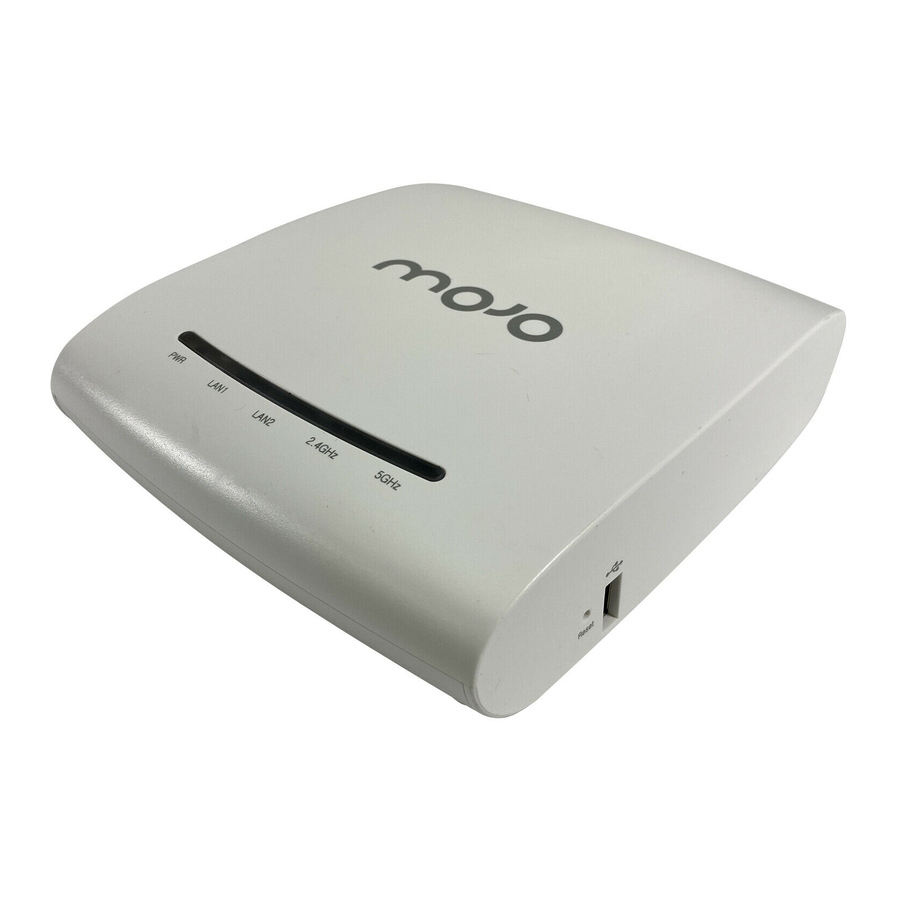
- Page 8 C-75 Overview C-75 is a 3x3 802.11a/b/g/n/ac access point/sensor. This chapter provides an overview of the C-75 and describes front and the rear panels. The front panel of the C-75 has 5 LEDs that indicate the working of the device.
- Page 9 Note: LAN2 is ON if the link is up, and is OFF if the link is down. The 2.4 GHz and 5 GHz LEDs blink when there is activity on the respective radio(s). Table 0-2. LED Details for C-75 in Sensor mode Power LAN2 2.4 GHz...
- Page 10 The rear panel of the C-75 has an Ethernet port labelled LAN1, that enables you to connect the device a wired LAN through a switch or a hub and provides the power for the device by using the 802.3af standard.
- Page 11 After reset, all the LEDs will blink once, indicating that the reset is successful, and the system boot sequence is initiated. .The USB port connects the C-75 to a USB device. If you are using the cellular activity detection device to detect cellular activity, you must plug it in to the USB port.
- Page 12 (802.1Q capable) on a switch. The device then monitors the VLANs that are configured on that trunk port and are chosen by the user. In this mode, an C-75 can monitor up to 16 VLANs. The wireless interface of the sensor is enabled for WIPS operations.
- Page 13 Mount C-75 Take a configured C-75, that is, ensure that a static IP is assigned to the device or the settings have been changed for DHCP. Note the MAC address and the IP address of the device in a safe place before it is installed in a hard-to-reach location.
- Page 14 Figure 0-2 Wall Mounting C-75 Installation Guide...
- Page 15 Power on C-75 A C-75 device can be powered on by 802.3af Class 0 Power Over Ethernet (PoE) of Nominal input voltage 48V DC. You can connect the device to the network using PoE or a power adapter. Connect C-75 to the Network To connect C-75 to the network, perform the following steps.
- Page 16 Ensure that a DHCP server is available on the network to provide network configuration to the C-75. Connect one end of the network interface cable to the Ethernet port at the rear of the C-75. Connect the other end of the network interface cable to an Ethernet jack on the desired subnet.
- Page 17 Log on to the server through SSH and run the get sensor list command. You would see a list of all Mojo devices that are recognized by the server. Mojo One users can go to the Devices tab in Mojo Wireless Manager and check whether the device is visible under the Devices tab.
- Page 18 Device is placed on a subnet that is not DHCP enabled. Configuring AP through Config Shell The Config Shell supports a pre-defined set of commands used to configure the C-75 device. Log in to the device console using the SSH shell.
- Page 19 The wireless interface of the ND is disabled. In this mode, a C-75 functioning as a WIPS sensor can detect and monitor up to 100 VLANs. Use the set mode command to set the device mode for C-75.
- Page 20 Choose option 1 to configure VLANs for DHCP and option 2 to configure VLANs with static IP address. The device will restart / reboot after the VLAN configuration. To configure VLANs with DHCP, you must provide comma-separated VLAN IDs. See the figure below for configuring VLAN with DHCP. C-75 Installation Guide...
- Page 21 2. Choose option 3 from the menu that appears. Configure a static IP address in absence of a DHCP server Connect a crossover cable from the computer to the Ethernet port of C-75. Configure the LAN IP address on the computer in the subnet 192.168.1.0/24.
- Page 22 Remove the crossover connection to the computer and connect the Ethernet port to the local switch. Configure IPv6 settings C-75 is IPv6 capable. Use the set ipv6 config command to configure advanced options such as DHCP settings, auto negotiation, and manual configuration. ...
- Page 23 C-75 Config Shell Commands The following tables detail the C-75 config shell commands. Table 0-1 get Commands get Commands Command Description get ap Displays all the currently visible APs get channel util Displays the current channel utilization in %, non-Wi-Fi interference in %, and noise floor values in dBm when device is in AP mode.
- Page 24 Runs through the current VLAN and IP config wizard. set server discovery Sets the server discovery information. set vlan config Configures list of VLANs and their network settings to be monitored by ND. set ipv6 config Sets IPv6 network settings. C-75 Installation Guide...
- Page 25 RSSI value in dbm, IP address/hostname of the presence notification server parameters and time interval in seconds. The RSSI value can range between -127 and 0 dbm. The time interval can range between 0 and 14400 seconds. C-75 Installation Guide...
- Page 26 . The factory default IP address of the device is 192.168.1.245. upgrade Upgrades the AP manually from a given IP address presence notification Enables the presence notification feature. enable presence notification Disables the presence notification feature. disable C-75 Installation Guide...
- Page 27 C-75 Troubleshooting Following are the troubleshooting guidelines for C-75. Symptoms Diagnosis Solution The device did not Ensure that the DHCP server is on and available on the receive a valid IP VLAN/subnet to which the device is connected. If the...
- Page 28 Note : Although the server is backward compatible, that is, older version sensors can connect to a newer version server, this is not recommended. C-75 Installation Guide...
Need help?
Do you have a question about the C-75 and is the answer not in the manual?
Questions and answers