Ceragon FibeAir IP-20S Installation And User Manual
Hide thumbs
Also See for FibeAir IP-20S:
- Installation manual (105 pages) ,
- User manual (945 pages) ,
- User manual (597 pages)

Related Manuals for Ceragon FibeAir IP-20S


Summary of Contents for Ceragon FibeAir IP-20S
- Page 1 Installation and User Guide ® FibeAir IP-20S Part ID: BM-0280-0 | Doc ID: DOC-00038494 Rev F.10 February 2018 © Copyright 2018 by Ceragon Networks Ltd. All rights reserved.
- Page 2 Installation and User Guide for FibeAir IP-20S Notice This document contains information that is proprietary to Ceragon Networks Ltd. No part of this publication may be reproduced, modified, or distributed without prior written authorization of Ceragon Networks Ltd. This document is provided as is, without warranty of any kind.
-
Page 3: Table Of Contents
Installation and User Guide for FibeAir IP-20S Table of Contents 1. Before You Start......................8 Important Notes........................... 8 Safety Precautions & Declared Material ..................9 1.2.1 General Equipment Precautions ....................9 1.2.2 Précautions générales relatives à l'équipement ................ 10 1.2.3 Allgemeine Vorsichtsmaßnahmen für die Anlage ..............10 Pre-Installation Instructions ....................... - Page 4 Installation and User Guide for FibeAir IP-20S Connecting an Optical Fiber Cable and SFP ................30 3.8.1 General Installation Procedure ....................35 Connecting a DC Power Cable ....................39 3.10 Connecting the Ethernet Cable ....................43 3.10.1 Preparing the Ethernet Cable and Plug-in Field ................. 43 3.10.2 Preparing the Ethernet Cable Already Assembled ..............
- Page 5 Installation and User Guide for FibeAir IP-20S List of Figures Figure 1: IP-20S Rear View (Left) and Front View (Right) ............12 Figure 2: Cable Gland Construction ..................12 Figure 3: IP-20S Interfaces ...................... 13 Figure 4: PoE Injector ......................14 Figure 5: PoE Injector Ports .....................
- Page 6 Installation and User Guide for FibeAir IP-20S List of Tables Table 1: Ethernet Cable Color Code ..................27 Table 2: Ethernet Cable Electrical Requirements ..............27 Table 3: Ethernet Cable Mechanical/Environmental Requirements ........27 Table 4: Outdoor DC Cable Electrical Requirements............... 28 Table 5: Outdoor DC Cable Mechanical/Environmental Requirements .........
- Page 7 Installation and User Guide for FibeAir IP-20S About This Guide This guide describes the FibeAir IP-20S installation procedures and provides additional information concerning system parts and frequency bands. What You Should Know For the warranty to be honored, install the unit in accordance with the instructions in this manual.
-
Page 8: Before You Start
• Changes or modifications to this equipment not expressly approved by the party responsible for compliance (Ceragon Networks Ltd.) could void the user’s authority to operate the equipment. • NOTE: This equipment has been tested and found to comply with the limits for a Class B digital device, pursuant to part 15 of the FCC Rules. -
Page 9: Safety Precautions & Declared Material
To avoid malfunctioning or personnel injuries, equipment or accessories/kits/plug-in unit installation, requires qualified and trained personnel. Changes or modifications not expressly approved by Ceragon Networks could void the user's authority to operate the equipment. Where special cables, shields, adapters and grounding kits are supplied or described in this manual, these items must be used, to comply with the FCC regulations. -
Page 10: Précautions Générales Relatives À L'équipement
Installation and User Guide for FibeAir IP-20S Utrustning som är kopplad till skyddsjord via jordat vägguttag och/eller via annan utrustning och samtidigt är kopplad till kabel-TV nät kan i vissa fall medfőra risk főr brand. Főr att undvika detta skall vid anslutning av utrustningen till kabel-TV nät galvanisk isolator finnas mellan... -
Page 11: Transportation And Storage
Check the packing lists and ensure that correct parts numbers quantities of goods have arrived. Inspect for any damage on the cases and equipment. Report any damage or discrepancy to a Ceragon representative, by e-mail or fax. Page 11 of 83... -
Page 12: Product Hardware Description
Installation and User Guide for FibeAir IP-20S Product Hardware Description IP-20S Hardware Overview FibeAir IP-20S features an all-outdoor architecture consisting of a single unit directly mounted on the antenna. Figure 1: IP-20S Rear View (Left) and Front View (Right) Figure 2: Cable Gland Construction... -
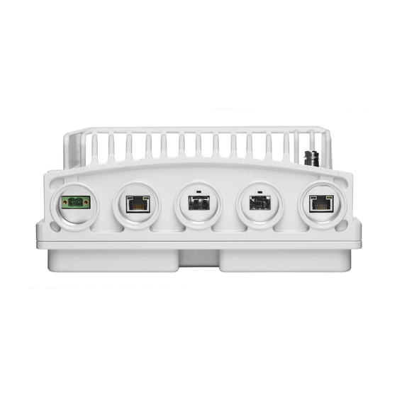
Page 13: Ip-20S Interfaces
Installation and User Guide for FibeAir IP-20S 2.1.1 IP-20S Interfaces Figure 3: IP-20S Interfaces Data Port 1 for GbE traffic: • ◦ Electric: 10/100/1000Base-T. Supports PoE. ◦ Optical: 1000Base-X (optional) • Data Port 2 for GbE traffic: ◦ Electric10/100/1000Base-T ◦... -
Page 14: Poe Injector
Installation and User Guide for FibeAir IP-20S PoE Injector The PoE injector is an outdoor unit which can be mounted on a wall, pole, or indoor rack. Each PoE Injector kit includes the following items: PoE injector • • 2 DC power connectors... -
Page 15: System Components
Installation and User Guide for FibeAir IP-20S System Components The following figures show the main components used in the IP-20S installation procedures. Figure 6: IP-20S Figure 7: Twist Figure 8: PoE Injector Page 15 of 83 Ceragon Proprietary and Confidential... -
Page 16: Antenna Connection
Installation and User Guide for FibeAir IP-20S Antenna Connection FibeAir iP-20S can be ordered with any of the following antennas: • 1 ft antennas: AN-3501-1 AN-2505-0 2 ft antennas: • AN-3315-1 AN-2517-1 2.4.1 Antenna Specifications for 1 ft Antennas The following table lists the specifications for each available 1 ft antenna. -
Page 17: Antenna Specifications For 2 Ft Antennas
Installation and User Guide for FibeAir IP-20S AN-2505-0 AN-3501-1 RPE Number 906-HAE2603 BL 10587 Mechanical Specifications Wind Velocity Operational, km/h Wind Velocity Survival Rating, km/h Ice Load, mm Azimuth Adjustment, Degrees ±15 ±15 Elevation Adjustment, Degrees ±15 ±15 Mounting Pipe Diameter, mm... - Page 18 Installation and User Guide for FibeAir IP-20S AN-2517-0 AN-3315-1 Radome type UV Stabilized PC Hard Cover Packing type Carton Carton Gross weight, kg 11.2 – 12.4 18±2 Packed dimensions, mm 720/480 (L) X 790 (W) X 320 (H) 750 (L) X 750 (W) X 440 (H) Packing Volume, m 0.144...
- Page 19 Installation and User Guide for FibeAir IP-20S AN-2517-0 AN-3315-1 Vibration ETSI 300 019-2-4 V2.2.2 (2003-04) ETSI 300 019-2-4 V2.2.2 (2003-04) T4.1E. 4M5 T4.1E. RoHS 2002/95/EC Compliant Compliant Page 19 of 83 Ceragon Proprietary and Confidential...
-
Page 20: Power Specifications
Installation and User Guide for FibeAir IP-20S Power Specifications 2.5.1 Electrical Requirements • -48V DC Nominal Maximum current rating 1.5 A • • Maximum Cable length 300 meter • Maximum cable size for PoE cable is 24 AWG, with maximum current up to 2A from the power source. -
Page 21: Cable Installation And Grounding
Installation and User Guide for FibeAir IP-20S Cable Installation and Grounding Minimum and Maximum Cable Diameter To fit the gland, the outer cable diameter should be between 6-10 mm. This applies to all glands on both the IP-20S unit and the PoE Injector. -
Page 22: Grounding Procedure
Installation and User Guide for FibeAir IP-20S 3.2.1 Grounding Procedure Required Tools • Metric offset wrench key wrench #3 Metric wrench 10mm • Procedure 1 On the front of each IP-20S unit, loosen the nut, plain washer, and serrated washer from the GND stud, using the metric offset hexagon key and the wrench. -
Page 23: Power Source
Installation and User Guide for FibeAir IP-20S Power Source The power cable must be plugged into the unit before turning on the external power. When selecting a power source, the following must be considered: DC power can be from -40 VDC to -60 VDC. -
Page 24: Available Cable Options
Installation and User Guide for FibeAir IP-20S Available Cable Options 3.5.1 Fiber Optic Cables - Single Mode Marketing P/N Description IP-20_FO_SM_LC2LC_ARM_7m CABLE,FO,DUAL LC/LC,7M,SM,55mm OPEN END,M28 GLAND,ARMORED,OU IP-20_FO_SM_LC2LC_ARM_15m CABLE,FO,DUAL LC/LC,15M,SM,55mm OPEN END,M28 GLAND,ARMORED,O IP-20_FO_SM_LC2LC_ARM_30m CABLE,FO,DUAL LC/LC,30M,SM,55mm OPEN END,M28 GLAND,ARMORED,O IP-20_FO_SM_LC2LC_ARM_50m CABLE,FO,DUAL LC/LC,50M,SM,55mm OPEN END,M28... -
Page 25: Fiber Optic Cables - Multi Mode
Installation and User Guide for FibeAir IP-20S 3.5.2 Fiber Optic Cables - Multi Mode Marketing P/N Description IP-20_FO_MM_LC2LC_ARM_7m CABLE,FO,DUAL LC/LC,7M,MM,55mm OPEN END,M28 GLAND,ARMORED,OU IP-20_FO_MM_LC2LC_ARM_15m CABLE,FO,DUAL LC/LC,15M,MM,55mm OPEN END,M28 GLAND,ARMORED,O IP-20_FO_MM_LC2LC_ARM_20m CABLE,FO,DUAL LC/LC,20M,MM,55mm OPEN END,M28 GLAND,ARMORED IP-20_FO_MM_LC2LC_ARM_30m CABLE,FO,DUAL LC/LC,30M,MM,55mm OPEN END,M28... -
Page 26: Ethernet Cable And Specifications
Installation and User Guide for FibeAir IP-20S 3.5.4 Ethernet Cable and Specifications Marketing P/N Description CAT5E_SFUTP_Outdoor_50m CABLE,RJ45 TO RJ45 STR 50M,CAT-5E,ETHER,UV CAT5E_SFUTP_Outdoor_75m CABLE,RJ45 TO RJ45 STR 75M,CAT-5E,ETHER,UV CAT5E_SFUTP_Outdoor_305m_drum CABLE,MATERIAL,CAT-5E,SFUTP,4X2X24AWG,UV RESISTANCE,305M CAT5E_Arm_50m CABLE,RJ45 TO RJ45 STR,50M,CAT-5E,M28 GLAN,ARM,UV RESISTANCE CAT5E_Arm_70m CAT5E_Arm_75mCABLE,RJ45 TO RJ45... -
Page 27: Outdoor Ethernet Cable Specifications
Installation and User Guide for FibeAir IP-20S Table 1: Ethernet Cable Color Code Pair Wire A Wire B WHITE-blue BLUE WHITE-orange ORANGE WHITE-green GREEN WHITE-brown BROWN 3.5.5 Outdoor Ethernet Cable Specifications Table 2: Ethernet Cable Electrical Requirements Cable type CAT-5e SFUTP, 4 pairs, according to ANSI/TIA/EIA-568-B-... -
Page 28: Outdoor Dc Cable Specifications
Installation and User Guide for FibeAir IP-20S 3.5.6 Outdoor DC Cable Specifications Table 4: Outdoor DC Cable Electrical Requirements tinned Cable type copper wires Wire gage 18 AWG (for <100m installations) 12 AWG (for >100m installations) Stranding stranded Voltage rating... -
Page 29: Special Instructions For Use Of Glands
Installation and User Guide for FibeAir IP-20S Table 6: Cable Clamps Part Number Marketing Model Item Description SI-1229-0 Fiber_clamp_2cbl_4.0-7.0mm DUAL FEADER CLAMP FOR 4.0-7.0mm CABLE 2 WAY. SI-1230-0 Fiber_clamp_4cbl_4.0-7.0mm DUAL FEADER CLAMP FOR 4.0-7.0mm CABLE 4 WAY. SI-1231-0 Fiber_clamp_6cbl_4.0-7.0mm DUAL FEADER CLAMP FOR 4.0-7.0mm CABLE 6 WAY. -
Page 30: Connecting An Optical Fiber Cable And Sfp
Installation and User Guide for FibeAir IP-20S In order to remove the plastic plugs for the unit, you can use the flange of supplied glands to disconnect them. See below pictures Connecting an Optical Fiber Cable and SFP To connect an optical fiber cable and the SFP transceiver: 1 Use a pre-assembled cable. - Page 31 Installation and User Guide for FibeAir IP-20S 2 Split the connector into two separate LC connectors (one for each fiber). 3 Remove the gland cap and rubber from the gland body. 4 Slide the gland cap into the cable. 5 Slide the rubber into the cable.
- Page 32 Installation and User Guide for FibeAir IP-20S 6 Insert the wires with the connectors one by one into the cable gland. 7 Secure the cable to the lip of the gland using a tie wrap. Important Note: If you are raising the cable to a radio unit on a tower, this step is crucial to prevent the cable from slipping from the gland, which could damage the connector.
- Page 33 Installation and User Guide for FibeAir IP-20S 8 Connect the fibers to the SFP transceiver. Listen for the “click” to ensure that it is fully inserted. 9 Remove the tie wrap securing the cable to the gland. Note: A new tie wrap must be used to secure the cable to the gland at the end of the procedure, as described in Step 13.
- Page 34 Installation and User Guide for FibeAir IP-20S 12 Tighten the gland cap. Important Note! Before tightening the gland, make sure the gland is aligned with the tapped hole in the unit. Tightening the gland at an angle can ruin the thread on the gland and prevent proper sealing of the interface Tighten the gland gently and make sure there is no resistance.
-
Page 35: General Installation Procedure
Installation and User Guide for FibeAir IP-20S 3.8.1 General Installation Procedure This procedure applies to all cable types, and explains how to install the cables using long glands. The gland is supplied assembled. 1 Before inserting a cable, you must disassemble the gland cap and gland rubber from the gland body. - Page 36 Installation and User Guide for FibeAir IP-20S 4 Slide the cable into the body of the gland. If you are using a gland cap (see Step 5), make sure to leave enough space for the gland cap to fit into the gland without disturbing the cable.
- Page 37 Installation and User Guide for FibeAir IP-20S The M28 gland cap has hook on top. After attaching the gland cap to the gland, you can connect a rope to the hook and use this to lift the gland and cable up to the radio unit. Before screwing the gland into the radio unit, you must remove the gland cap.
- Page 38 Installation and User Guide for FibeAir IP-20S 9 Screw the gland into the radio unit until there is full contact between the gland and the radio unit. Important Note! Before tightening the gland, make sure the gland is aligned with the tapped hole in the unit. Tightening the gland at an angle can ruin the thread on the gland and prevent proper sealing of the interface.
-
Page 39: Connecting A Dc Power Cable
Installation and User Guide for FibeAir IP-20S Figure 9: Tightening the Front Portion Figure 10: Tightening the Rear Portion of the Gland of the Gland 12 Secure the cable to the lip of the gland using a tie wrap. Connecting a DC Power Cable Note: The DC power cable and connector must be ordered separately. - Page 40 Installation and User Guide for FibeAir IP-20S 4 Insert the power cable wires into the power connector. 5 Insert the power cable wires into the power connector. Match “+” to the 0V wire and “-“ to the -48V wire. 6 Tighten the two top screws.
- Page 41 Installation and User Guide for FibeAir IP-20S 8 Tighten the two front screws. Page 41 of 83 Ceragon Proprietary and Confidential...
- Page 42 Installation and User Guide for FibeAir IP-20S 9 Screw the gland into the radio unit Important Note! Before tightening the gland, make sure the gland is even with the cover. Tighten the gland gently and make sure there is no resistance.
-
Page 43: Connecting The Ethernet Cable
Installation and User Guide for FibeAir IP-20S 3.10 Connecting the Ethernet Cable If you need to assemble the Ethernet cable, follow the instructions in section 3.10.1, Preparing the Ethernet Cable and Plug-in Field, then proceed to section 3.10.3, Connection of Ethernet Cable to IP-20S. - Page 44 Installation and User Guide for FibeAir IP-20S Note: Cord colors should be matched to the same pins on both ends of the cable. 6 Trim all wires to the same length. About 12 mm on the left should be exposed from the inner sheath.
-
Page 45: 3.10.2 Preparing The Ethernet Cable Already Assembled
Installation and User Guide for FibeAir IP-20S 11 Crimp the RJ45 plug with the crimp tool. Make sure the twisted braid is crimped firmly to the RJ45 plug. 12 Verify that the wires ended up the correct order and that the wires extend to the front of the RJ45 plug and make good contact with the metal contacts in the RJ45 plug. -
Page 46: 3.10.3 Connection Of Ethernet Cable To Ip-20S
Installation and User Guide for FibeAir IP-20S 3.10.3 Connection of Ethernet Cable to IP-20S To connect the Ethernet cable to the IP-20S: 1 Remove the relevant cap from the IP-20S radio. You can use the side of the gland to unscrew the cap. - Page 47 Installation and User Guide for FibeAir IP-20S 3 Screw the gland into the radio unit. Important Note! Before tightening the gland, make sure the gland is even with the cover. Tighten the gland gently and make sure there is no resistance.
-
Page 48: Poe Injector Installation And Connection
Installation and User Guide for FibeAir IP-20S PoE Injector Installation and Connection PoE Injector Cable Connection The PoE Injector cables are connected similar to the IP-20S. To connect the Ethernet (CAT5E) cable to the PoE or Data port, refer to •... -
Page 49: Poe Injector Grounding
Installation and User Guide for FibeAir IP-20S PoE Injector Grounding To ground the PoE Injector: 1 On the right side of each PoE Injector, loosen the screw, plain washer, and serrated washer. 2 Place the cable lug (supplied with the PoE injector kit) between the plain and serrated washer. - Page 50 Installation and User Guide for FibeAir IP-20S 4 Place the washers on the bolt. 5 Tighten the nuts. Page 50 of 83 Ceragon Proprietary and Confidential...
-
Page 51: Poe Injector Pole Mount Installation
Installation and User Guide for FibeAir IP-20S PoE Injector Pole Mount Installation List of Items Item Description Quantity Remarks PoE Injector Required Tools • Slot Screwdriver Procedure To mount the PoE Injector on a pole: 1 Mount and tighten the PoE Injector to a pole with a diameter of 114 mm using a stainless steel hose clamp. -
Page 52: Poe Injector 19" Rack Installation
Installation and User Guide for FibeAir IP-20S PoE Injector 19” Rack Installation List of Items Item Description Quantity Remarks PoE Injector PoE Injector 19” Rack Mount Required Tools • Philips Screwdriver To mount the PoE Injector on a rack: 1 Mount the PoE Injector to a 19” rack using a 19” rack adaptor. -
Page 53: Poe Injector Etsi Rack Installation
Installation and User Guide for FibeAir IP-20S PoE Injector ETSI Rack Installation List of Items Item Description Quantity Remarks PoE Injector PoE Injector ETSI Rack Mount Kit Required Tools • Philips Screwdriver To mount the PoE Injector to an ETSI rack: 1 Mount the PoE Injector to an ETSI rack using a 19”... - Page 54 Installation and User Guide for FibeAir IP-20S 3 Mount the PoE Injector on the adaptor through the wall mounting holes using M6 screws and washers. 4 Mount the 19” rack adaptor with the ETSI ears on the ETSI rack using four M6 screws and cage nuts.
-
Page 55: Generic Installation Procedures And Notes
Installation and User Guide for FibeAir IP-20S Generic Installation Procedures and Notes Torque Requirements When tightening the captive screws, use 20 Nm torque for radio-antenna, radio- mediation device, and mediation device-antenna connections. In order to avoid misalignment, screws should be tightened progressively. -
Page 56: Figure 11: Mount Ip-20S Dc Pole Mount To Pole
Installation and User Guide for FibeAir IP-20S Figure 11: Mount IP-20S DC Pole Mount to Pole Page 56 of 83 Ceragon Proprietary and Confidential... -
Page 57: Ip-20S Detailed Configurations Description
Installation and User Guide for FibeAir IP-20S IP-20S Detailed Configurations Description 1+0 Direct Mount Installation List of Items Item Description Quantity Remarks IP-20S RADIO Required Tools The following tools are required for the IP-20S installation: • Metric offset hexagon key wrench #6 •... -
Page 58: Figure 12: Horizontal / Vertical Pole
Installation and User Guide for FibeAir IP-20S Figure 12: Horizontal / Vertical Pole Figure 13: Twist Orientation Page 58 of 83 Ceragon Proprietary and Confidential... - Page 59 Installation and User Guide for FibeAir IP-20S ◦ For horizontal polarization, locate the twist with the letter “H” vertical to the hook cover and fasten the two screws. ◦ For vertical polarization, locate the twist with the letter “V” vertical to the hook cover and fasten the two screws.
- Page 60 Installation and User Guide for FibeAir IP-20S Note: Make sure the polarization mounting direction of the IP-20S is correct. Page 60 of 83 Ceragon Proprietary and Confidential...
-
Page 61: Antenna Installation Instructions
Installation and User Guide for FibeAir IP-20S Antenna Installation Instructions Note: Appropriate lubricant or grease can be applied to the screws that connect the IP-20S to the antenna interface. Installation Instructions for 1 ft Antenna List of Items Item Description... - Page 62 Installation and User Guide for FibeAir IP-20S Page 62 of 83 Ceragon Proprietary and Confidential...
-
Page 63: Antenna Assembly Procedure
Installation and User Guide for FibeAir IP-20S Required Tools Required Tool Head Size Thread Size Torque Nm Allen Key 3 mm Allen Key 4 mm Allen Key 8 mm Combination Wrench (ring/open jaw) 13 mm 24/32 Socket wrench and sockets... -
Page 64: Figure 14: Right Side Antenna Installation
Installation and User Guide for FibeAir IP-20S Figure 14: Right Side Antenna Installation Figure 15: Left Side Antenna Installation Step 2.1 – Antenna support (right side installation). a) Mount the pivot bracket (1) to the antenna (2) using 1 M8x35 screw and 1 M8 washer (3) and 2 M8x25 screws with 2 M8 washers (4). - Page 65 Installation and User Guide for FibeAir IP-20S Step 2.2 – Antenna support (left side installation). a) Mount the pivot bracket (1) to the antenna (2) using 1 M8x35 screw with 1 M8 washer (3) and 2 M8x25 screws with 2 M8 washers (4). Fit the screws finger tight.
- Page 66 Installation and User Guide for FibeAir IP-20S Step 3 – Adapter Plate. If the adapter plate (2) is already mounted, skip Step 3 and go directly to Step 4. a) Mount the adapter plate (2) onto the antenna (1) using 4 M10x25 screws with 4 M10 washers (3).
- Page 67 Installation and User Guide for FibeAir IP-20S Step 4 – Interface Plate. If the Interface plate (1) is already mounted, skip Step 4 and go directly to Step 5. a) Mount the interface plate (1) to the adapter plate (2) using 2 M6x18 screws (3).
-
Page 68: Antenna Installation Procedure
Installation and User Guide for FibeAir IP-20S Step 6 – Apply Extra Grease. For heavier radio equipment it is recommended to add extra grease to the antenna support, to reduce friction. a) Apply a layer of grease onto surfaces A and B on Pivot bracket (1). -
Page 69: Figure 16: Clamp Orientation For Pipes Ø50-66Mm (32Nm)
Installation and User Guide for FibeAir IP-20S Figure 16: Clamp orientation for pipes Ø50-66mm (32Nm) Figure 17: Clamp orientation for pipes Ø66-120mm (24Nm) Page 69 of 83 Ceragon Proprietary and Confidential... -
Page 70: Antenna Alignment Procedure
Installation and User Guide for FibeAir IP-20S Antenna Alignment Procedure 7.4.1 Elevation Adjustment a) Ensure that the 3 M8 screws (1) are slightly loose. b) Rotate the elevation screw to adjust the direction ± 15°. c) On completion, tighten the screws (1) with torque of 24 Nm ± 5%. -
Page 71: Installation Instructions For 2 Ft Antenna
Installation and User Guide for FibeAir IP-20S Installation Instructions for 2 ft Antenna List of Items Item Description Quantity Remarks Antenna Antenna support (Box) (not preassembled) Pipe attachment bracket Clamp bracket Pivot bracket M8 link screw (and M8 nut) M8x100 screw... - Page 72 Installation and User Guide for FibeAir IP-20S Page 72 of 83 Ceragon Proprietary and Confidential...
- Page 73 Installation and User Guide for FibeAir IP-20S Required Tools Required Tool Head Size Thread Size Torque Nm Allen Key 3 mm Allen Key 4 mm Allen Key 8 mm Combination Wrench (ring/open jaw) 13 mm 24/32 Socket wrench and sockets...
-
Page 74: Antenna Assembly Procedure
Installation and User Guide for FibeAir IP-20S Antenna Assembly Procedure Step 1 – Radome a) Detach the spherical radome (1) from the reflector (2) by unscrewing 1 M4 screw and 1 square nut (3). b) Dismount the edge ring (4) and turn the spherical radome (1) 180°. -
Page 75: Figure 18: Right Side Antenna Installation
Installation and User Guide for FibeAir IP-20S Step 2 – Left or right side installation Before proceeding with the installation, you must determine whether a left or right side installation is required. For a right side installation, see Step 3.1 – Antenna support (right side installation). - Page 76 Installation and User Guide for FibeAir IP-20S d) Mount the pipe attachment bracket (8) to the pivot bracket (1) using 1 M8x100 screw (10) and 2 M8 nuts with 3 M8 washers (11). Fit the screw and nuts loosely. Page 76 of 83...
- Page 77 Installation and User Guide for FibeAir IP-20S Step 3.2 – Antenna support (left side installation). a) Mount the pivot bracket (1) to the antenna (2) using 1 M8x35 screw with 1 M8 washer (3) and 2 M8x25 screws with 2 M8 washers (4). Fit the screws finger tight.
- Page 78 Installation and User Guide for FibeAir IP-20S Step 4 – Feeder. a) If the feeder (1) and interface plate (2) are already mounted (24-42GHz), remove the interface plate (2) from the feeder by removing the 2 M6 screws (3). b) Insert the feeder (1) into the antenna (4) using 4 M4x10 screws (5). Tighten the screws with torque of 2.6Nm ±...
- Page 79 Installation and User Guide for FibeAir IP-20S Step 5 – Adapter Plate. a) Mount the adapter plate (2) onto the antenna (1) using 4 M10x25 screws with 4 M10 washers (3). First make sure that the adapter plate guide pins are properly inserted into the feeder (4), then tighten the screws with torque of 33Nm ±...
- Page 80 Installation and User Guide for FibeAir IP-20S Step 6 – Interface Plate. a) Mount the interface plate (1) to the adapter plate (2) using 2 M6x18 screws (3). Tighten the screws with torque of 9.1Nm ± 5%. Step 7 – Selecting Polarization.
-
Page 81: Antenna Installation Procedure
Installation and User Guide for FibeAir IP-20S Step 8 – Apply Extra Grease. For heavier radio equipment it is recommended to add extra grease to the antenna support, to reduce friction. a) Apply a layer of grease onto surfaces A and B on Pivot bracket (1). -
Page 82: Figure 20: Clamp Orientation For Pipes Ø50-66Mm (32Nm)
Installation and User Guide for FibeAir IP-20S Figure 20: Clamp orientation for pipes Ø50-66mm (32Nm) Figure 21: Clamp orientation for pipes Ø66-120mm (24Nm) Page 82 of 83 Ceragon Proprietary and Confidential... -
Page 83: Antenna Alignment Procedure
Installation and User Guide for FibeAir IP-20S Antenna Alignment Procedure 7.8.1 Elevation Adjustment a) Ensure that the 3 M8 screws (1) are slightly loose. b) Rotate the elevation screw to adjust the direction ± 15°. c) On completion, tighten the screws (1) with torque of 24 Nm ± 5%.
Need help?
Do you have a question about the FibeAir IP-20S and is the answer not in the manual?
Questions and answers