Ceragon FibeAir IP-20C Installation Manual
Hide thumbs
Also See for FibeAir IP-20C:
- User manual (597 pages) ,
- Installation manual (171 pages) ,
- User manual (945 pages)

Related Manuals for Ceragon FibeAir IP-20C


Summary of Contents for Ceragon FibeAir IP-20C
- Page 1 FibeAir IP-20C ® Installation Guide Part ID: BM-0266-0 Doc ID: DOC-00036522 Rev A.14 February 2015 Copyright © 2015 by Ceragon Networks Ltd. All rights reserved.
- Page 2 Installation Guide Notice This document contains information that is proprietary to Ceragon Networks Ltd. No part of this publication may be reproduced, modified, or distributed without prior written authorization of Ceragon Networks Ltd. This document is provided as is, without warranty of any kind.
-
Page 3: Table Of Contents
Surge Protection ......................33 Securing the Cables ..................... 34 Special Instructions for use of Glands ................. 35 3.5.1 General Installation Procedure ..................36 Connecting an Optical Fiber Cable and SFP ............... 39 Ceragon Proprietary and Confidential Page 3 of 156... - Page 4 MultiCore 2+2 HSB Double Polarization Direct Mount ..........87 MultiCore 2+2 HSB Double Polarization Remote Mount ..........91 6.6.1 Common Installation ....................92 6.6.2 6-13 GHz ........................94 6.6.3 15-42 GHz ........................96 Ceragon Proprietary and Confidential Page 4 of 156...
- Page 5 6.18.2 11 GHz only ....................... 147 6.18.3 6-11GHz ........................148 7. Installing IP-20C on Third-Party Antenna Adaptors ........152 Special Note on Converting ValuLine 3 Antennas ............. 153 8. Appendix A: Mediation Device Losses ............155 Ceragon Proprietary and Confidential Page 5 of 156...
- Page 6 FibeAir® IP-20C Installation Guide About This Guide This guide describes the FibeAir IP-20C installation procedures and provides additional information concerning system parts and frequency bands. What You Should Know For the warranty to be honored, install the unit in accordance with the instructions in this manual.
-
Page 7: Before You Start
To avoid malfunctioning or personnel injuries, equipment or accessories/kits/plug-in unit installation, requires qualified and trained personnel. Changes or modifications not expressly approved by Ceragon Networks could void the user's authority to operate the equipment. Where special cables, shields, adapters and grounding kits are supplied or described in this manual, these items must be used, to comply with the FCC regulations. -
Page 8: Précautions Générales Relatives À L'équipement
électriques. Bruit de machine d’ordre - 3. GPSGV, le plus haut niveau de pression sonore s'élève à 70 dB (A) au maximum, dans le respect de la norme ISO EN 7779. Ceragon Proprietary and Confidential Page 8 of 156... -
Page 9: Allgemeine Vorsichtsmaßnahmen Für Die Anlage
Marking is done according to standard practice unless otherwise specified by customers. The following details should be marked: Customers address Contract No Site name (if known) Case No Ceragon Proprietary and Confidential Page 9 of 156... -
Page 10: Inspection
Check the packing lists and ensure that correct parts numbers quantities of goods have arrived. Inspect for any damage on the cases and equipment. Report any damage or discrepancy to a Ceragon representative, by e-mail or fax. Ceragon Proprietary and Confidential... -
Page 11: Product Hardware Description
Product Hardware Description IP-20C Hardware Overview IP-20C features an all-outdoor dual-carrier architecture consisting of a single unit directly mounted on the antenna. IP-20C Rear View (Left) and Front View (Right) Cable Gland Construction Ceragon Proprietary and Confidential Page 11 of 156... -
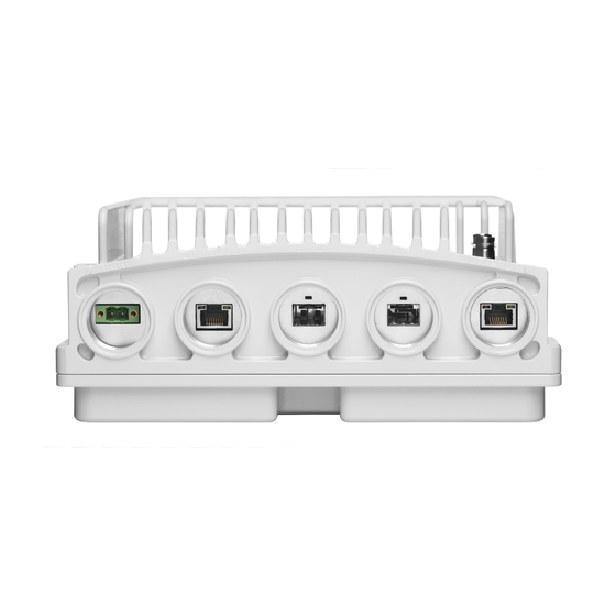
Page 12: Ip-20C Interfaces
Optical: 1000Base-SX (or X-LX-ZX/XD) Power interface (-48VDC) Management Port: 10/100Base-T 2 RF Interfaces : Standard interface per frequency band RSL interface: BNC connector Source sharing: TNC connector Grounding screw Ceragon Proprietary and Confidential Page 12 of 156... -
Page 13: Channel-Port Mapping To Polarization
An IP-20C assembly for this example would look as follows: Radio Port ID (EMS ID) Channels Coverage Port 2 Ch 7-8 Port 1 Ch 1-2 Note: The same orientation is maintained for TX-H and TX-L units. Ceragon Proprietary and Confidential Page 13 of 156... - Page 14 Ch 1-2 Port 1 Ch 7-8 Please note that when selecting two operational channels that are not covered by the same diplexer, certain TX-TX separation and TX-RX separation criteria should be met. Ceragon Proprietary and Confidential Page 14 of 156...
- Page 15 Installation Guide Separation Criteria when Working with Two Diplexer Types Because diplexer coverage and channelization plans vary in different parts of the world for specific applications, please consult with Ceragon pre-sales representatives for support. Ceragon Proprietary and Confidential Page 15 of 156...
-
Page 16: Multicore Mediation Devices (Mcmd)
MCMDs must be connected to the IP-20C using a Grounding Jumper. See Grounding for MultiCore Mediation Devices on page 30. MCMD type Functionality Splitter Combines the two carriers using the same polarization Combines the two carriers on alternate polarizations (H,V) Splitter Ceragon Proprietary and Confidential Page 16 of 156... -
Page 17: Poe Injector
The PoE injector is an outdoor unit which can be mounted on a wall, pole, or indoor rack. Each PoE Injector kit includes the following items: PoE injector 2 caps Wall mount accessories 2 DC power connectors PoE Injector Ceragon Proprietary and Confidential Page 17 of 156... -
Page 18: Poe Injector Interfaces
The presence of a specific component in this manual does not indicate that it is available for ordering. Please consult with your respective pre-sales engineer for specific component availability. IP-20C Dual Core Coupler/Splitter DC OMT Ceragon Proprietary and Confidential Page 18 of 156... - Page 19 FibeAir® IP-20C Installation Guide Remote Pole Mount Remote Dual Pole Mount DC Splitter Dual Core Mediation Adaptor for 6-13 GHz PoE Injector Device Ceragon Proprietary and Confidential Page 19 of 156...
-
Page 20: Adaptors And Installation Kits
20C_DUAL_CORE_MD 20C_DUAL_CORE_MD_ t_6G _kit_7_8G D_kit_10-11G D_kit_13G _kit_15G kit_18G IP-20C DC ADAPTOR REMOTE IP-20C_7- IP-20C_10- 20C_13G_Rmt_Mnt_a MOUNT KIT 20C_6G_Rmt_Mnt_adpt 8G_Rmt_Mnt_adpt 11G_Rmt_Mnt_adpt IP-20C DC REMOTE MOUNT IP-20C_RM_OMT_10- 20C_RM_OMT_7_8G_ OMT ADAPTOR KIT 20C_RM_OMT_6G_adpt 11G_adpt adpt Ceragon Proprietary and Confidential Page 20 of 156... - Page 21 IP-20C DC REMOTE MOUNT KIT IP-20C-Pole-Mount RFU-C ADAPTOR REMOTE MOUNT KIT RFU-C6-RM_ADAPT RFU-C7_8-RM_ADAPT RFU-C10_11-RM_ADAPT RFU-C13-RM_ADAPT Flx-WG-3FT-15 RFU-C WG Kit Flx-WG-4FT-6 Flx-WG-4FT-7_8 Flx-WG-4FT-10_11 Flx-WG-3FT-13 ADPT_RFU-C15-RM_mill RFU-C ADAPTOR TO FLEX WG (IMPERIAL) KIT ADPT_RFU-C6-RM_mill ADPT_RFU-C7_8-RM_mill ADPT_RFU-C10_11-RM_mill ADPT_RFU-C13-RM_mill Ceragon Proprietary and Confidential Page 21 of 156...
- Page 22 ADPT_RFU-C15- ADPT_RFU-C18- ADPT_RFU-C23- ADAPTOR KIT DM_1500P DM_1500P DM_1500P DM_1500P DM_1500P 1500P Adaptors - 26GHz – 42GHz 1500P Adaptors 26GHz 28-31GHz 32GHz 38GHz 42GHz RFU-C-PHOSPHORUS DM ADAPTOR KIT ADPT_RFU-C26-DM_1500P ADPT_RFU-C28-DM_1500P ADPT_RFU-C32-DM_1500P ADPT_RFU-C38-DM_1500P NA Ceragon Proprietary and Confidential Page 22 of 156...
- Page 23 INT-A RFU-C13-OMT-INT- RFU-C15-OMT-INT- RFU-C18-OMT-INT- RFS 1FT 1FT-R 1FT-R 1FT-R RFU-C6-OMT-INT-2_6FT- RFU-C7_8-OMT-INT- RFU-C10_11-OMT- RFU-C13-OMT-INT- RFU-C15-OMT-INT- RFU-C18-OMT-INT- RFS 2-6FT 2_6FT-R INT-2_6FT-R 2_6FT-R 2_6FT-R 2_6FT-R RFU-C6L-OMT-INT-RW RFU-C10_11-OMT- RFU-C15-OMT-INT- RFU-C18-OMT-INT- Radio Waves RFU-C7_8-OMT-INT-RW RFU-C13-OMT-INT-RW /RFU-C6H-OMT-INT-RW INT-RW Ceragon Proprietary and Confidential Page 23 of 156...
- Page 24 15GHz 18GHz RFU-C10_11-OMT- RFU-C15-OMT-INT- RFU-C18-OMT-INT- Shenglu RFU-C7_8-OMT-INT-SH RFU-C13-OMT-INT-SH INT-SH RFU-C10_11-OMT- RFU-C15-OMT-INT- RFU-C18-OMT-INT- Xian Putian (Ceragon branding) RFU-C6-OMT-INT-CR RFU-C7_8-OMT-INT-CR RFU-C13-OMT-INT-CR INT-CR RFU-C10_11-OMT- Xian Putian (OEM branding) RFU-C6-OMT-INT-X RFU-C7_8-OMT-INT-X RFU-C13-OMT-INT-X RFU-C15-OMT-INT-X RFU-C18-OMT-INT-X INT-X Antenna Circ. Adapters for OMT – 23GHz – 42GHz Note: This adapter is not required if the antenna is equipped with a circular feeder.
- Page 25 PoE Injector all outdoor, -48VDC (Default offering) POE Injector all outdoor, redundant DC input, +24VDC support and -48VDC PoE_Inj_AO_2DC_24V_48V support PoE_Inj_19inch_Rack_Mnt_kit PoE Injector 19” Rack Mount Kit PoE_Inj_ETSI_Rack_Mnt_kit PoE Injector ETSI Rack Mount Kit Ceragon Proprietary and Confidential Page 25 of 156...
-
Page 26: Antenna Connection
UG383/U UG383/U If a different antenna type (CPR flange) is used, a flange adaptor is required. Please contact your Ceragon representative for details. Note! Appropriate lubricant or grease can be applied to the screws that connect the IP-20C to the antenna interface. -
Page 27: Power Specifications
Temperature range for exceptional temperatures; tested successfully, with limited margins: -45°C (-49°F) to +60°C (140°F) Humidity: 5%RH to 100%RH IEC529 IP66 Storage: ETSI EN 300 019-1-1 Class 1.2 Transportation: ETSI EN 300 019-1-2 Class 2.3 Ceragon Proprietary and Confidential Page 27 of 156... -
Page 28: Cable Installation And Grounding
For optical (SFP) cables (see Connecting an Optical Fiber Cable and SFP on page 39), no grounding is required. For Ethernet cables, the cable should be grounded to the antenna tower every 50m, using the kit CAT5E_gnd_kit. Ceragon Proprietary and Confidential Page 28 of 156... -
Page 29: Grounding Procedure
20A, shall be installed for full power disconnection in a building installation. Any outdoor antenna cable shield shall be permanently connected to protective earth in a building installation. Ceragon Proprietary and Confidential Page 29 of 156... -
Page 30: Grounding For Multicore Mediation Devices
3 .1.1, connect the other end of the Grounding Jumper to the IP-20C grounding screw, along with the IP-20C grounding cable. The order in which you place the two cables is not important. Ceragon Proprietary and Confidential Page 30 of 156... -
Page 31: Power Source
IP-20 Fiber Optic Multi Mode LC2LC Outdoor use 50m IP-20_FO_MM_LC2LC_OUT_75m IP-20 Fiber Optic Multi Mode LC2LC Outdoor use 75m IP-20_FO_MM_LC2LC_OUT_100m IP-20 Fiber Optic Multi Mode LC2LC Outdoor use 100m IP-20_FO_MM_LC2LC_OUT_300m IP-20 Fiber Optic Multi Mode LC2LC Outdoor use 300m Ceragon Proprietary and Confidential Page 31 of 156... -
Page 32: Dc Cable And Connector
IP-20_MIMO_Prot_ mng_spltr IP-20C MIMO or Prot management odu spltr Ethernet Cable and Specifications 3.2.5 Marketing P/N Description CABLE,MATERIAL,CAT-5E,SFUTP,4X2X24AWG,UV CAT5E_SFUTP_Outdoor_305m_drum RESISTANCE,305M This cable has the following specifications: Suitable for: Fast Ethernet Gigabit Ethernet Ceragon Proprietary and Confidential Page 32 of 156... -
Page 33: Surge Protection
Surge Protection Requirements section of the IP-20C Technical Description, provided the Ethernet cables were prepared according to the instructions in Preparing the Ethernet Cable and Plug-in Field on page 46. Ceragon Proprietary and Confidential Page 33 of 156... -
Page 34: Securing The Cables
Item Description SI-1114-0 Fiber_clamp_6cbl_6.5-7.5mm DUAL FEADER CLAMP FOR 6.5-7.5mm CABLE 6 WAY. SI-1113-0 Fiber_clamp_4cbl_6.5-7.5mm DUAL FEADER CLAMP FOR 6.5-7.5mm CABLE 4 WAY. SI-0954-0 Fiber_clamp_2cbl_6.5-7.5mm DUAL FEEDER CLAMP FOR 6.5-7.5mm CABLE 2 WAY. Ceragon Proprietary and Confidential Page 34 of 156... -
Page 35: Special Instructions For Use Of Glands
Glands Kit Marketing Model Marketing Description IP-20_Glands_kit IP-20_Glands_x5_kit In order to remove the plastic plugs for the unit, you can use the flange of supplied glands to disconnect them. See below pictures Ceragon Proprietary and Confidential Page 35 of 156... -
Page 36: General Installation Procedure
3.5.1 The gland is supplied assembled. 1 Before inserting a cable. you must disassemble the gland cap and gland rubber from the gland body. 2 Slide the gland cap into the cable. Ceragon Proprietary and Confidential Page 36 of 156... - Page 37 If there is resistance, stop immediately, and thread out the gland. Verify that the gland thread is not damaged and tighten the gland again. If the gland thread is damaged do not use it! Ceragon Proprietary and Confidential Page 37 of 156...
- Page 38 Important Note! Pay attention that the gland rubber is properly located and not damaged during the tightening of the gland cap. 7 Secure the cable to the gland using a tie wrap. Ceragon Proprietary and Confidential Page 38 of 156...
-
Page 39: Connecting An Optical Fiber Cable And Sfp
3 Remove the gland cap and rubber from the gland body. 4 Slide the gland cap into the cable. 5 Slide the rubber into the cable. 6 Insert wires with connector one by one into the cable gland. Ceragon Proprietary and Confidential Page 39 of 156... - Page 40 FibeAir® IP-20C Installation Guide 7 Connect the wires to the SFP transceiver. Listen for the “click” to ensure that it is fully inserted. 8 Connect the connector into the IP-20C plug connector. Ceragon Proprietary and Confidential Page 40 of 156...
- Page 41 Then, tighten the gland again. If the gland thread is damaged do not use it! Ceragon Proprietary and Confidential Page 41 of 156...
- Page 42 FibeAir® IP-20C Installation Guide 11 Secure the cable to the gland using a tie wrap. Ceragon Proprietary and Confidential Page 42 of 156...
-
Page 43: Connecting A Dc Power Cable
4 Insert the power cable wires into the power connector. 5 Match “+” and “–” to the red and black cord colors according to the power supply connection cord colors. 6 Tighten the two top screws. Ceragon Proprietary and Confidential Page 43 of 156... - Page 44 FibeAir® IP-20C Installation Guide 7 Plug the power cable with connector into the IP-20C power connector. 8 Tighten the two front screws. Ceragon Proprietary and Confidential Page 44 of 156...
- Page 45 Tightening the gland at an angle can ruin the thread on the gland and prevent proper sealing of the interface. 10 Tighten the gland cap. 11 Secure the cable to the gland with a tie wrap. Ceragon Proprietary and Confidential Page 45 of 156...
-
Page 46: Connecting The Ethernet Cable
5 Trim all wires to the same length. About 12 mm on the left should be exposed from the inner sheath. 6 Separate the wires and place the twisted shield between the separated wires. 7 Release the gland cap slightly. Ceragon Proprietary and Confidential Page 46 of 156... - Page 47 Ethernet cable should extend into the plug by about 13 mm and held in place by the crimp. The twisted shield should be placed outside of and in the back of the connector. Ceragon Proprietary and Confidential Page 47 of 156...
-
Page 48: Preparing The Ethernet Cable Already Assembled
ANSI/TIA/EIA-568-B-2. Preparing the Ethernet Cable Already Assembled 3.8.2 To prepare the Ethernet cable already assembled: 1 Release the gland cap and the gland rubber slightly. Ceragon Proprietary and Confidential Page 48 of 156... -
Page 49: Connection Of Ethernet Cable To Ip-20C
To connect the Ethernet cable to the IP-20C: 1 Remove the relevant cap from the IP-20C radio. You can use the side of the gland to unscrew the cap. 2 Connect the CAT5E cable to the IP-20C. Ceragon Proprietary and Confidential Page 49 of 156... - Page 50 Tightening the gland at an angle can ruin the thread on the gland and prevent proper sealing of the interface. Ceragon Proprietary and Confidential Page 50 of 156...
- Page 51 FibeAir® IP-20C Installation Guide 4 Tighten the gland cap. 5 Secure the cable to the gland using a tie wrap. Ceragon Proprietary and Confidential Page 51 of 156...
-
Page 52: Management Connection For 4X4 Mimo And 1+1/2+2 Hsb Configurations
(MGT/PROT) of the two IP-20C units and provide management access to each unit. The MIMO/Protection signaling cables are available pre-assembled from Ceragon in various lengths, but users can also prepare them in the field. The following sections explain how to prepare and connect these cables. Preparing a MIMO/Protection Signaling Cable 3.9.1... - Page 53 The following figure demonstrates a 4x4 MIMO configuration in which both IP-20C units are connected to an external management station and to each other, using two splitters. 4x4 MIMO or HSB Protection Configuration with External Management Ceragon Proprietary and Confidential Page 53 of 156...
-
Page 54: Poe Injector Installation And Connection
1 On the right side of each PoE Injector, loosen the screw, plain washer, and serrated washer. 2 Place the cable lug (supplied with the PoE injector kit) between the plain and serrated washer. 3 Tighten the screw. Ceragon Proprietary and Confidential Page 54 of 156... -
Page 55: Poe Injector Wall Mount Installation
2 Drill two 6mm diameter holes with 100mm distance between the center of the holes. 3 Insert the anchors with the bolts. 4 Place the washers on the bolt. 5 Tighten the nuts. Ceragon Proprietary and Confidential Page 55 of 156... - Page 56 FibeAir® IP-20C Installation Guide Ceragon Proprietary and Confidential Page 56 of 156...
-
Page 57: Poe Injector Pole Mount Installation
The Hose Clamp is not supplied with PoE injector kit. 3 Attach the PoE injector to the pole. 4 Connect the ends of the hose clamp. 5 Tighten the hose clamp using the captive screw. Ceragon Proprietary and Confidential Page 57 of 156... -
Page 58: Poe Injector 19" Rack Installation
2 Mount the PoE Injector on the 19” adaptor through the wall mounting holes, using M6 screws and washers. 3 Mount the 19” rack adaptor to a 19” rack using four M6 screws and cage nuts. Ceragon Proprietary and Confidential Page 58 of 156... - Page 59 FibeAir® IP-20C Installation Guide Ceragon Proprietary and Confidential Page 59 of 156...
-
Page 60: Poe Injector Etsi Rack Installation
1 Mount the PoE Injector to an ETSI rack using a 19” rack adaptor and ETSI adapting ears. 2 Connect the ETSI adapting ears to a 19” rack adaptor using four M6 screws. Ceragon Proprietary and Confidential Page 60 of 156... - Page 61 4 Mount the 19” rack adaptor with the ETSI ears on the ETSI rack using four M6 screws and cage nuts. Note: For this type of installation, a 2RU space is required. Ceragon Proprietary and Confidential Page 61 of 156...
-
Page 62: Generic Installation Procedures
To install the IP-20C pole mount: Mount and tighten the IP-20C DC pole mount to a pole with a diameter of 114 mm using the four washers and screws supplied with the IP-20C DC pole mount kit. Ceragon Proprietary and Confidential Page 62 of 156... - Page 63 Mount and tighten the IP-20C Remote Mount Adaptor plate (supplied in IP- 20C Adaptor Remote Mount kit) to the IP-20C Pole Mount using the four flat screws supplied with the IP-20C Adaptor Remote Mount kit. Ceragon Proprietary and Confidential Page 63 of 156...
-
Page 64: Remote Mount Installation For Single Polarization With An Imperial Waveguide
RFU-C Adaptation kit to Flexible WG Imperial. 2 Mount and tighten the IP-20C Splitter to the RFU-C Remote Pole Mount using the four captive screws and washers that are assembled to the IP- 20C Splitter kit. Ceragon Proprietary and Confidential Page 64 of 156... - Page 65 O-rings are mounted on the IP-20C Splitter kit. 4 Connect the Flexible Waveguide and Sealing Gasket supplied with the Flexible Waveguide Imperial Kit to the RFU-C Adaptor plate. Tighten the four screws supplied with the Flexible Waveguide Imperial Kit. Ceragon Proprietary and Confidential Page 65 of 156...
-
Page 66: 15-42Ghz Installation Procedure
1 Loosen the two screws, and remove the twist plate from the IP-20C Splitter. 2 Mount and tighten the IP-20C Splitter to the RFU-C Remote Pole Mount using the four captive screws and washers that are assembled to the IP- 20C Splitter kit. Ceragon Proprietary and Confidential Page 66 of 156... - Page 67 4 Connect the Flexible Waveguide and Sealing O-ring supplied with the Flexible Waveguide Imperial Kit to the IP20-C Splitter kit. Tighten the four screws supplied with the RFU-C Adaptation kit to the Flexible Waveguide Imperial. Ceragon Proprietary and Confidential Page 67 of 156...
- Page 68 FibeAir® IP-20C Installation Guide Ceragon Proprietary and Confidential Page 68 of 156...
-
Page 69: Management Connection For Mimo And Protection Configurations
The MIMO/Protection signaling cables are available pre-assembled from Ceragon in various lengths (refer to Cables for MIMO Connections on page 32), but you can also prepare them in the field. The following sections explain how to prepare and connect these cables. -
Page 70: Connecting A Mimo/Protection Splitter
MIMO/Protection signaling port (“MIMO/Prot”) – A standard CAT5E cable or a MIMO/Protection signaling cable should be connected between this port and the other “MIMO/Prot” port of the second splitter on the mate IP-20C unit. Ceragon Proprietary and Confidential Page 70 of 156... - Page 71 FibeAir® IP-20C Installation Guide The following figures demonstrate a 4x4 MIMO configuration in which both IP-20C units are connected to an external management station and to each other, using two splitters. Ceragon Proprietary and Confidential Page 71 of 156...
-
Page 72: Installation Procedures Per Configuration Type
Metric offset hexagon key set Metric wrench key set Insertion Loss Mediation Devices Signal Path / Remarks Insertion Loss [dB] 13-15 23-26 28-42 Each IP-20C antenna port to Mediation device antenna port Ceragon Proprietary and Confidential Page 72 of 156... - Page 73 2 Connect the OMT Kit to the antenna and secure it with four screws. Verify the existence of the O-ring. 3 Connect the IP-20C DC radio to the OMT Kit using the four M8 captive screws and washers supplied, and tighten the screws. Ceragon Proprietary and Confidential Page 73 of 156...
- Page 74 FibeAir® IP-20C Installation Guide Ceragon Proprietary and Confidential Page 74 of 156...
-
Page 75: Multicore 2+0 Dual Polarization Remote Mount
Per Antenna Vendor. Not used for standard Circ./Circ. Adaptor interface antennas (six feet and larger). Required Tools Metric offset hexagon key set Metric wrench key set Phillips #1, #2 screwdriver Insertion Loss Ceragon Proprietary and Confidential Page 75 of 156... -
Page 76: Common Installation
(Remove the existing rectangular transition, swap the O-ring, and install the circular transition instead.) 2 Connect the OMT Kit to the antenna and secure it with four screws. Verify the existence of the O-ring. Ceragon Proprietary and Confidential Page 76 of 156... -
Page 77: Ghz
1 Mount and tighten the IP-20C Remote Mount Adaptor plate (supplied in IP-20C Adaptor Remote Mount kit) to the IP-20C Pole Mount using the four flat screws supplied with the IP-20C Adaptor Remote Mount kit. Ceragon Proprietary and Confidential Page 77 of 156... - Page 78 O-rings are mounted on the IP-20C Remote Mount Adaptor. 3 Mount and tighten both Flexible WGs with their O-ring to the IP-20C Remote Mount Adaptor ports using the four screws supplied with each Flexible WG kit. Ceragon Proprietary and Confidential Page 78 of 156...
-
Page 79: Ghz
1 Mount and tighten the IP-20C to the IP-20C DC Pole Mount using the four screws assembled on the IP-20C. 2 Mount and tighten the O-ring and the Flexible WG to IP-20C radio ports using the four screws supplied with the Flexible WG kit. Ceragon Proprietary and Confidential Page 79 of 156... -
Page 80: Multicore 2+0 Single Polarization Direct Mount
1 Adjust the twist on the Splitter Kit. Perform one of the following steps, according to the required polarization (horizontal or vertical). For horizontal polarization, locate the holes above and below the letter “H” on the pins and fasten the two screws. Ceragon Proprietary and Confidential Page 80 of 156... - Page 81 2 Mount and tighten the IP-20C Splitter Kit on the antenna using the four M8 screws and washers. 3 Mount and tighten the IP-20C to the IP-20C Splitter Kit using the four M8 captive screws and washers supplied. Ceragon Proprietary and Confidential Page 81 of 156...
-
Page 82: Multicore 2+0 Single Polarization Remote Mount
Phillips #1, #2 screwdriver Metric wrench key set Insertion Loss Insertion Loss [dB] Mediation Signal Path / Remarks 13-15 23-26 28-42 Devices Splitter and Radio to antenna port one WG Ceragon Proprietary and Confidential Page 82 of 156... -
Page 83: Ghz
RFU-C Adaptor Remote Mount kit. 2 Mount and tighten the IP-20C Splitter to the RFU-C Pole Mount using the four captive screws and washers that are assembled to the IP-20C Splitter kit. Ceragon Proprietary and Confidential Page 83 of 156... - Page 84 O-rings are mounted on the IP-20C Splitter kit. 4 Connect the Flexible Waveguide and Sealing Gasket supplied with the Flexible Waveguide Kit to the RFU-C Adaptor plate. Tighten the four screws supplied with the Flexible Waveguide Kit. Ceragon Proprietary and Confidential Page 84 of 156...
-
Page 85: Ghz
1 Loosen the two screws and remove the twist plate from the IP-20C Splitter. 2 Mount and tighten the IP-20C Splitter to the RFU-C Pole Mount using the four captive screws and washers that are assembled to the IP-20C Splitter kit. Ceragon Proprietary and Confidential Page 85 of 156... - Page 86 O-rings are mounted on the IP-20C Splitter kit. 4 Connect the Flexible Waveguide and Sealing Gasket supplied with the Flexible Waveguide Kit to the IP20-C Splitter kit. Tighten the four screws supplied with the Flexible Waveguide kit. Ceragon Proprietary and Confidential Page 86 of 156...
-
Page 87: Multicore 2+2 Hsb Double Polarization Direct Mount
Metric offset hexagon key set Metric wrench key set Insertion Loss Insertion Loss [dB] Mediation Signal Path / 13-15 23-26 28-42 Devices Remarks 18 GHz Main Paths Double Coupler and OMT Secondary Paths Ceragon Proprietary and Confidential Page 87 of 156... - Page 88 (Remove the existing rectangular transition, swap the O-ring, and install the circular transition instead.) 2 Connect the IP-20C OMT Kit to the antenna and secure it with four screws. Verify existence of the O-ring. Ceragon Proprietary and Confidential Page 88 of 156...
- Page 89 4 Mount and tighten the IP-20C DC radio unit to both sides of the Dual Coupler Kit using the supplied captive screws and washers. Pay attention that the O-rings are correctly mounted on the radio ports of the IP-20C Dual Coupler. Ceragon Proprietary and Confidential Page 89 of 156...
- Page 90 5 Connect the MIMO signaling cable between the management ports of both units. For additional instructions on preparing and connecting this cable, refer to Management Connection for MIMO and Protection Configurations on page 69. Ceragon Proprietary and Confidential Page 90 of 156...
-
Page 91: Multicore 2+2 Hsb Double Polarization Remote Mount
Metric wrench key set Phillips #1 , #2 screwdriver Insertion Loss Insertion Loss [dB] Mediation Signal Path / Remarks 13-15 23-26 28-42 Devices Double Main Paths Coupler, OMT Secondary Paths and two WGs Ceragon Proprietary and Confidential Page 91 of 156... -
Page 92: Common Installation
(Remove the existing rectangular transition, swap the O-ring, and install the circular transition instead.) 2 Connect the OMT Kit to the antenna and secure it with four screws. Verify the existence of the O-ring. Ceragon Proprietary and Confidential Page 92 of 156... - Page 93 4 Connect the protection signaling cable between the management ports of both units. For additional instructions on preparing and connecting this cable, refer to Management Connection for MIMO and Protection Configurations on page 69. Ceragon Proprietary and Confidential Page 93 of 156...
-
Page 94: Ghz
2 Mount and tighten the IP-20C Dual Coupler to the IP-20C Pole Mount using the four screws and washers that are supplied with the IP-20C Dual Coupler kit. Pay attention that the O-rings are mounted on the IP-20C Remote Mount Adaptor. Ceragon Proprietary and Confidential Page 94 of 156... - Page 95 4 Connect both Flexible Waveguides and Sealing Gaskets supplied with each Flexible Waveguide Kit to the IP-20C Dual Coupler antenna ports. Tighten the screws and washers supplied with the Flexible Waveguide Kit. Ceragon Proprietary and Confidential Page 95 of 156...
-
Page 96: Ghz
2 Mount and tighten the IP-20C radios on each side of the IP-20C Dual Coupler using the screws assembled on Ip-20C radio. Pay attention that the O-rings are correctly assembled on the radio port of the IP-20C Dual coupler. Ceragon Proprietary and Confidential Page 96 of 156... - Page 97 FibeAir® IP-20C Installation Guide 3 Mount the O-ring and the Flexible WG to IP-20C Dual Coupler ports using the four screws supplied with the Flexible WG kit. Ceragon Proprietary and Confidential Page 97 of 156...
-
Page 98: Multicore 2+2 Hsb Single Polarization Direct Mount
Metric offset hexagon key set Metric wrench key set Phillips #1 screwdriver Insertion Loss Insertion Loss [dB] Mediation Signal Path / Remarks 13-15 23-26 28-42 Devices Double Main Paths Coupler and Secondary Paths Splitter Ceragon Proprietary and Confidential Page 98 of 156... - Page 99 Vertical polarization: Locate the holes above and below the letter “V” on the pins and fasten the two screws. 2 Mount the Splitter Kit on the antenna using four M8 screws and washers and tighten the screws. Ceragon Proprietary and Confidential Page 99 of 156...
- Page 100 M8 screws and washers and tighten the screws. 4 Connect the IP-20C DC radio unit to both sides of the Dual Coupler Kit using the supplied captive screws and washers and tighten the screws. Ceragon Proprietary and Confidential Page 100 of 156...
- Page 101 5 Connect the protection signaling cable between the management ports of both units. For additional instructions on preparing and connecting this cable, refer to Management Connection for MIMO and Protection Configurations on page 69. Ceragon Proprietary and Confidential Page 101 of 156...
-
Page 102: Multicore 2+2 Hsb Single Polarization Remote Mount
Phillips #1, #2 screwdriver Insertion Loss Insertion Loss [dB] Mediation Signal Path / Remarks 13-15 23-26 28-42 Devices Main Paths Double Coupler, Splitter and WG Secondary Paths 10.7 10.9 11.2 11.5 Ceragon Proprietary and Confidential Page 102 of 156... -
Page 103: Ghz
RFU-C Adaptor Remote Mount kit. 2 Mount and tighten the IP-20C Splitter to the RFU-C Pole Mount using the four captive screws and washers that are assembled to the IP-20C Splitter kit. Ceragon Proprietary and Confidential Page 103 of 156... - Page 104 4 Mount and tighten the IP-20C Radio to the IP-20C Dual Coupler using the four screws and washers that are assembled to the IP-20C Radio. Pay attention that the O-rings are mounted on the IP-20C Dual Coupler. Ceragon Proprietary and Confidential Page 104 of 156...
- Page 105 6 Connect the protection signaling cable between the management ports of both units. For additional instructions on preparing and connecting this cable, refer to Management Connection for MIMO and Protection Configurations on page 69. Ceragon Proprietary and Confidential Page 105 of 156...
-
Page 106: Ghz
1 Loosen the two screws, and remove the twist plate from the IP-20C Splitter. 2 Mount and tighten the IP-20C Splitter to the RFU-C Pole Mount using the four captive screws and washers that are assembled to the IP-20C Splitter kit. Ceragon Proprietary and Confidential Page 106 of 156... - Page 107 4 Mount and tighten the IP-20C Radio to the IP-20C Dual Coupler using the four screws and washers that are assembled to the IP-20C radio. Pay attention that the O-rings are mounted on the IP-20C Dual Coupler. Ceragon Proprietary and Confidential Page 107 of 156...
- Page 108 6 Connect the protection signaling cable between the management ports of both units. For additional instructions on preparing and connecting this cable, refer to Management Connection for MIMO and Protection Configurations on page 69. Ceragon Proprietary and Confidential Page 108 of 156...
-
Page 109: Multicore 2+0 Dual Polarization Direct Mount
Metric offset hexagon key set Metric wrench key set Insertion Loss Insertion Loss [dB] Mediation Signal Path / Remarks 13-15 23-26 28-42 Devices Double Splitter Radio to antenna port and OMT Ceragon Proprietary and Confidential Page 109 of 156... - Page 110 (Remove the existing rectangular transition, swap the O-ring, and install the circular transition instead.) 2 Connect the IP-20C OMT Kit to the antenna and secure it with four screws. Verify existence of the O-ring. Ceragon Proprietary and Confidential Page 110 of 156...
- Page 111 4 Mount and tighten the IP-20C DC radio unit to both sides of the Dual Coupler Kit using the supplied captive screws and washers. Pay attention that the O-rings are correctly mounted on the radio ports of the IP-20C Dual Coupler. Ceragon Proprietary and Confidential Page 111 of 156...
-
Page 112: Multicore 2+0 Dual Polarization Remote Mount
Metric wrench key set Phillips #1 , #2 screwdriver Insertion Loss Insertion Loss [dB] Mediation Signal Path / Remarks 13-15 23-26 28-42 Devices Double Splitter, Radio to antenna port OMT and two WGs Ceragon Proprietary and Confidential Page 112 of 156... -
Page 113: 6.10.1 Common Installation Procedure
2 Connect the OMT Kit to the antenna and secure it with four screws. Verify the existence of the O-ring. 3 Mount and tighten the O-ring and the Flexible WG to IP-20C OMT ports using the four screws supplied with the Flexible WG kit. Ceragon Proprietary and Confidential Page 113 of 156... -
Page 114: 6.10.2 6-13 Ghz
2 Mount and tighten the IP-20C Dual Coupler to the IP-20C Pole Mount using the four screws and washers that are supplied with the IP-20C Dual Coupler kit. Pay attention that the O-rings are mounted on the IP-20C Remote Mount Adaptor. Ceragon Proprietary and Confidential Page 114 of 156... - Page 115 4 Connect both Flexible Waveguides and Sealing Gaskets supplied with each Flexible Waveguide Kit to the IP-20C Dual Coupler antenna ports. Tighten the screws and washers supplied with the Flexible Waveguide Kit. Ceragon Proprietary and Confidential Page 115 of 156...
-
Page 116: 6.10.3 15-42 Ghz
2 Mount and tighten the IP-20C radios on each side of the IP-20C Dual Coupler using the screws assembled on IP-20C radio. Pay attention that the O-rings are correctly assembled on the radio port of the IP-20C Dual Coupler. Ceragon Proprietary and Confidential Page 116 of 156... - Page 117 FibeAir® IP-20C Installation Guide 3 Mount the O-ring and the Flexible WG to IP-20C Dual Coupler ports using the four screws supplied with the Flexible WG kit. Ceragon Proprietary and Confidential Page 117 of 156...
-
Page 118: Multicore 2+0 Single Polarization Direct Mount
Metric offset hexagon key set Metric wrench key set Phillips #1 screwdriver Insertion Loss Insertion Loss [dB] Mediation Signal Path / Remarks 13-15 23-26 28-42 Devices Double Splitter Radio to antenna port and splitter Ceragon Proprietary and Confidential Page 118 of 156... - Page 119 Vertical polarization: Locate the holes above and below the letter “V” on the pins and fasten the two screws. 2 Mount the Splitter Kit on the antenna using four M8 screws and washers and tighten the screws. Ceragon Proprietary and Confidential Page 119 of 156...
- Page 120 M8 screws and washers and tighten the screws. 4 Connect the IP-20C DC radio unit to both sides of the Dual Coupler Kit using the supplied captive screws and washers and tighten the screws. Ceragon Proprietary and Confidential Page 120 of 156...
-
Page 121: 2X2 Los Mimo Direct Mount
Signal Path / 13-15 23-26 28-42 Devices Remarks Radio to antenna Dual Core (upper path) Mediation Device WG port to second Frequency band and WG length (antenna separation) and WG antenna dependent Ceragon Proprietary and Confidential Page 121 of 156... - Page 122 For vertical polarization, locate the holes above and below the letter “V” on the pins and fasten the two screws. 2 If not required, remove the plate assembled to the bended part of the dual core kit. Ceragon Proprietary and Confidential Page 122 of 156...
- Page 123 4 Connect the IP-20C radio to the IP-20C dual core kit using four M8 screws and washers and tighten the screws. Important: Verify that the O-rings are properly mounted between the dual core and the radio. Ceragon Proprietary and Confidential Page 123 of 156...
- Page 124 6 Connect the flexible waveguide to the IP-20C dual core kit using O-ring, screws and washers supplied with flexible waveguide kit and tighten the screws. Important: Verify that the O-rings are properly mounted between the dual core and the flexible waveguide flange. Ceragon Proprietary and Confidential Page 124 of 156...
- Page 125 Place O-ring and tighten screws and washers supplied with Coax to WG adapter kit. Important: Verify that the O-rings are properly mounted between the dual core and the Coax to WG flange. Ceragon Proprietary and Confidential Page 125 of 156...
-
Page 126: 2X2 Los Mimo Remote Mount
Metric wrench key set Insertion Loss Insertion Loss [dB] Mediation Signal Path / Remarks 13-15 23-26 28-42 Devices IP-20C antenna port to Frequency band and WG length (antenna separation) antenna port dependent Ceragon Proprietary and Confidential Page 126 of 156... -
Page 127: 6.13.1 For 6-13 Ghz
Pay attention that the O-rings are mounted on the IP-20C Remote Mount Adaptor. 3 Mount and tighten both Flexible WGs with their O-ring to the IP-20C Remote Mount Adaptor ports using the four screws supplied with each Flexible WG kit. Ceragon Proprietary and Confidential Page 127 of 156... -
Page 128: 6.13.2 15-42Ghz
FibeAir® IP-20C Installation Guide 6.13.2 15-42GHz 1 Mount and tighten the IP-20C radio to the IP-20C DC Pole Mount using the four screws assembled on the IP-20C radio. Ceragon Proprietary and Confidential Page 128 of 156... - Page 129 Flexible WG kit. 3 Mount and tighten the O-ring and flexible WG to both antenna ports using the four screws supplied with the flexible WG kit. Ceragon Proprietary and Confidential Page 129 of 156...
-
Page 130: 4X4 Los Mimo Direct Mount
Metric wrench key set Insertion Loss Mediation Signal Path / Remarks Insertion Loss [dB] Devices 13-15 23-26 28-42 OMT for Each IP-20C antenna port to each IP-20C Mediation device antenna port Ceragon Proprietary and Confidential Page 130 of 156... - Page 131 MultiCore 2+0 Dual Polarization Direct Mount on page 72. 2 Connect the source sharing cable between both EXT REF IP-20C radio connectors. The maximum torque for connecting this cable to the radio is 5Lb.in (0.5N.m). Ceragon Proprietary and Confidential Page 131 of 156...
- Page 132 FibeAir® IP-20C Installation Guide 3 Connect the MIMO data sharing cable between both ETH3/EXT IP-20C radio connectors. Ceragon Proprietary and Confidential Page 132 of 156...
- Page 133 4 Connect the MIMO signaling cable between the management ports of both units. For additional instructions on preparing and connecting this cable, refer to Management Connection for MIMO and Protection Configurations on page 69. Ceragon Proprietary and Confidential Page 133 of 156...
-
Page 134: 4+0 Dual Polarization, 2+2Hsb Single/Dual Polarization Direct Mount
2 Connect the IP-20C DC radios using the four M8 captive screws and washers supplied, and tighten the screws. Important: Verify that the O-rings are properly mounted between the Dual Coupler/Splitter ports and the radio. Ceragon Proprietary and Confidential Page 134 of 156... -
Page 135: 4+0 With Dual Circulator (6-11Ghz) Direct Mount
The regulation specifies a channelization of 8 consecutive 28/38MHz channels (1-8 ch). The actual channels in use are channels 1,5. Ch. 5 Radio Ch. 1 Radio Antenna Ports 1 2 3 4 5 6 7 8 Ceragon Proprietary and Confidential Page 135 of 156... -
Page 136: 4+0 Dual Polarization, 2+2Hsb Dual Polarization Remote Mount
Metric wrench key set Common Installation 1 Connect the OMT kit to the antenna and secure it with four screws. Important: Verify that the O-ring is properly mounted between the antenna transition and the OMT. Ceragon Proprietary and Confidential Page 136 of 156... -
Page 137: 6.16.1 6-13Ghz
IP-20C Dual Coupler kit. Pay attention that the O-rings are mounted on the IP-20C Remote Mount Adaptor. Mount IP-20C Dual Coupler to the IP-20C Pole Mount Ceragon Proprietary and Confidential Page 137 of 156... - Page 138 Flexible Waveguide Kit to the IP-20C Dual Coupler antenna ports. Tighten the screws and washers supplied with the Flexible Waveguide Kit. Connect Flexible Waveguides and Sealing Gaskets to IP-20C Dual Coupler Antenna Ports Ceragon Proprietary and Confidential Page 138 of 156...
-
Page 139: 6.16.2 15-42Ghz
Coupler. Mount IP-20C Radios on IP-20C Dual Coupler 3 Mount the O-ring and the Flexible Waveguides to the IP-20C Dual Coupler ports using the four screws supplied with the Flexible Waveguide kits. Ceragon Proprietary and Confidential Page 139 of 156... - Page 140 4 Mount and tighten the O-ring and the Flexible Waveguides to the IP-20C OMT ports using the four screws supplied with the Flexible Waveguide kits. Important: Verify that the O-rings are correctly mounted between the OMT ports and each Flexible Waveguide. Ceragon Proprietary and Confidential Page 140 of 156...
-
Page 141: 4+0 With Dual Circulator (6-11Ghz) Remote Mount
The regulation specifies a channelization of 8 consecutive 28/38MHz channels (1-8 ch). The actual channels in use are channels 1,5. Ch. 1 Radio Antenna Ch. 5 Radio Ports 1 2 3 4 5 6 7 8 Ceragon Proprietary and Confidential Page 141 of 156... -
Page 142: 2Hsb Single Polarization Remote Mount
IP-20C SPLITTER KIT IP-20C DUAL COUPLER KIT FLEXIBLE WG KIT RFU-C POLE MOUNT KIT Required Tools Metric offset hexagon key set Metric wrench key set Phillips #1, #2 screwdriver Ceragon Proprietary and Confidential Page 142 of 156... -
Page 143: 6.17.1 6-13Ghz
2 Mount and tighten the IP-20C Splitter to the RFU-C Pole Mount using the four captive screws and washers that are assembled to the IP-20C Splitter kit. Mount IP-20C Splitter to RFU-C Pole Mount Ceragon Proprietary and Confidential Page 143 of 156... - Page 144 4 Mount and tighten the IP-20C unit to the IP-20C Dual Coupler using the four screws and washers that are assembled to the IP-20C unit. Make sure that the O-rings are mounted on the IP-20C Dual Coupler. Mount IP-20C Radio to the IP-20C Dual Coupler Ceragon Proprietary and Confidential Page 144 of 156...
- Page 145 5 Connect the Flexible Waveguide and Sealing Gasket supplied with the Flexible Waveguide kit to the RFU-C Adaptor plate. Tighten the four screws supplied with the Flexible Waveguide kit. Mount Flexible Waveguide and Sealing Gasket to RFU-C Adaptor Plate Ceragon Proprietary and Confidential Page 145 of 156...
-
Page 146: Dual Circulator Multi-Carrier Kit Installation
Metric wrench key set Procedure 1 Mount and tighten the pillar adapter brackets to pole (supplied in IP-20C Adaptor Remote Mount kit). Tighten the four M10 Hex screws and washers supplied within the kit. Ceragon Proprietary and Confidential Page 146 of 156... -
Page 147: 6.18.1 6-8 Ghz
M8 Hex screws and washers supplied within the kit. 6.18.2 11 GHz only 1 Mount and tighten the IP-20C MC extender to the IP-20C pillar adapter bracket using the four M8 Hex screws and washers supplied within the kit. Ceragon Proprietary and Confidential Page 147 of 156... -
Page 148: 6.18.3 6-11Ghz
Circ using the four M8 Hex screws and washers supplied in the IP-20 Dual Circ kit. Pay attention that the O-rings on the IP-20C MC Dual Circ are well in place during the mounting. Ceragon Proprietary and Confidential Page 148 of 156... - Page 149 Dual Circ antenna ports using the four screws assembled on the IP-20C radio. Pay attention that the O-rings on the IP-20C MC Remote mount adapter are well in place during the mounting. Ceragon Proprietary and Confidential Page 149 of 156...
- Page 150 Remote mount adapter ports using the four screws supplied with the Flexible WG kit. 5 Mount and tighten the O-ring and flexible WG to both antenna ports using the four screws supplied with the flexible WG kit. Ceragon Proprietary and Confidential Page 150 of 156...
- Page 151 (i.e Ch1 V&H) Low Channels Radio (i.e Ch1 V&H) High Channels Radio (i.e Ch5 V&H) Antenna Ports 1 2 3 4 5 6 7 8 1 2 3 4 5 6 7 8 Ceragon Proprietary and Confidential Page 151 of 156...
-
Page 152: Installing Ip-20C On Third-Party Antenna Adaptors
Note: these third- instructions how to install party adaptors, refer to the FibeAir RFU-C Installation Guide, DOC- 00017708. Special Note on Converting ValuLine 3 Antennas on page 153. Ceragon Proprietary and Confidential Page 152 of 156... -
Page 153: Special Note On Converting Valuline 3 Antennas
ValuLine 3 antennas, 1-6ft. However, since there are some unique cases in which Andrew provided special antennas which are not supported by these adaptors, it is recommended that you supply your Ceragon representative with a picture of the current antenna (back plain side), in order to confirm the antenna’s compatibility prior to implementing this solution. - Page 154 FibeAir® IP-20C Installation Guide Ceragon Proprietary and Confidential Page 154 of 156...
-
Page 155: Appendix A: Mediation Device Losses
Dual Core Mediation Device Radio to antenna (upper path) Radio to antenna ports (V or H) Splitter Radio to antenna port Double Coupler Main Paths Secondary Paths Double Splitter Radio to antenna port Ceragon Proprietary and Confidential Page 155 of 156... - Page 156 If other antennas are to be used, an adaptor with a 0.1 dB loss should be considered. The numbers above represent the typical loss per component. The following diagram explains the circulators insertion loss: Ceragon Proprietary and Confidential Page 156 of 156...
Need help?
Do you have a question about the FibeAir IP-20C and is the answer not in the manual?
Questions and answers