
Related Manuals for Ceragon FibeAir IP-20C-HP


Summary of Contents for Ceragon FibeAir IP-20C-HP
- Page 1 Installation Guide ® FibeAir IP-20C-HP June 2019 | Rev B.03 © Copyright 2019 by Ceragon Networks Ltd. All rights reserved.
- Page 2 Installation Guide for FibeAir IP-20C-HP Notice This document contains information that is proprietary to Ceragon Networks Ltd. No part of this publication may be reproduced, modified, or distributed without prior written authorization of Ceragon Networks Ltd. This document is provided as is, without warranty of any kind.
-
Page 3: Table Of Contents
1.3.1 Packing ............................12 1.3.2 Transportation and Storage ....................... 12 1.3.3 Unpacking ..........................12 1.3.4 Inspection ..........................12 2. FibeAir IP-20C-HP Overview ..................13 IP-20C-HP Hardware Overview ....................14 2.1.1 IP-20C-HP Interfaces ........................15 System Components – Diplexer-Based Branching ..............16 2.2.1 Diplexer-Based Branching –... - Page 4 Installation Guide for FibeAir IP-20C-HP 4.5.2 Fiber Optic Cables - Multi Mode ....................35 4.5.3 DC Cable and Connector ......................35 4.5.4 Cables for MIMO Connections ....................35 4.5.5 Ethernet Cable and Specifications ..................... 36 Securing the Cables ........................40 Special Instructions for use of Glands ..................
- Page 5 Installation Guide for FibeAir IP-20C-HP 6.21 Dual Circulator Multi-Carrier Kit Installation ................135 6.22 AFR 1+0 Hub Site ........................141 7. Installation Instructions for Configurations with Channel Filter-Based Branching ..145 Channel Filter-Based Branching – Component Assembly ............145 7.1.1 Assembling the OCU Mounting Kit ..................145 7.1.2 Assembling the OCU ........................
- Page 6 Installation Guide for FibeAir IP-20C-HP List of Figures Figure 1: IP-20C-HP Rear View (Left) and Front View (Right) ............14 Figure 2: Cable Gland Construction ....................14 Figure 3: IP-20C-HP Interfaces ......................15 Figure 4: IP-20C-HP Radio Unit ......................16 Figure 5: IP-20C-HP Diplexer Unit .....................
- Page 7 Installation Guide for FibeAir IP-20C-HP Figure 35: 6 GHz – Mounting the First Adaptor ................98 Figure 36: 6 GHz – Mounting the Second Adaptor ................98 Figure 37: Mounting the Single Adaptor for 7, 8, 10, and 11 GHz ............ 99 Figure 38: 4+0 with Dual Circulator Direct Mount ................
- Page 8 Installation Guide for FibeAir IP-20C-HP List of Tables Table 1: IP-20C-HP Radio Unit Marketing Model Placeholders ............22 Table 2: IP-20C-HP Radio Unit Marketing Model Example ............... 22 Table 3: IP-20C-HP Diplexer Unit Marketing Model Placeholders ............ 23 Table 4: Diplexer Unit Marketing Model Examples ................23 Table 5: Marketing Models for Mediation Devices (Diplexer-Based Branching) ......
- Page 9 Installation Guide for FibeAir IP-20C-HP About This Guide This guide describes the FibeAir IP-20C installation procedures and provides additional information concerning system parts and frequency bands. What You Should Know For the warranty to be honored, install the unit in accordance with the instructions in this manual.
-
Page 10: Before You Start
To avoid malfunctioning or personnel injuries, equipment or accessories/kits/plug-in unit installation, requires qualified and trained personnel. Changes or modifications not expressly approved by Ceragon Networks could void the user's authority to operate the equipment. Where special cables, shields, adapters and grounding kits are supplied or described in this manual, these items must be used, to comply with the FCC regulations. -
Page 11: Précautions Générales Relatives À L'équipement
Installation Guide for FibeAir IP-20C-HP Machine noise information order - 3. GPSGV, the highest sound pressure level amounts to 70 dB (A) or less, in accordance with ISO EN 7779. Static electricity may cause body harm, as well as harm to electronic components inside the device. -
Page 12: Pre-Installation Instructions
Check the packing lists and ensure that correct parts numbers quantities of goods have arrived. Inspect for any damage on the cases and equipment. Report any damage or discrepancy to a Ceragon representative, by e-mail or fax. Page 12 of 204... -
Page 13: Fibeair Ip-20C-Hp Overview
Installation Guide for FibeAir IP-20C-HP FibeAir IP-20C-HP Overview FibeAir IP-20C-HP combines high TX power of up to 35 dBm with MultiCore radio technology, QPSK to 2048 QAM modulation, and line-of-sight (LoS) 4x4 MIMO in a compact, all-outdoor design. IP-20C-HP is easily and quickly deployable compared with fiber, enabling operators to achieve faster time to new revenue streams, lower total cost of ownership, and long- term peace of mind. -
Page 14: Ip-20C-Hp Hardware Overview
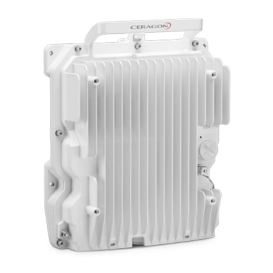
Installation Guide for FibeAir IP-20C-HP IP-20C-HP Hardware Overview IP-20C-HP features an all-outdoor dual-carrier architecture consisting of a single unit. Figure 1: IP-20C-HP Rear View (Left) and Front View (Right) Figure 2: Cable Gland Construction Page 14 of 204 Ceragon Proprietary and Confidential... -
Page 15: Ip-20C-Hp Interfaces
◦ Optical 1000Base-X (SFP) • Data Port 3/EXT ◦ Optical: 1000Base-X (SFP) ◦ Optical: Ceragon proprietary interface, if this port serves as an extension port for data sharing. • Management and Protection ◦ Electric 10/100Base-T (RJ-45) • 2 RF Interfaces – Standard interface per frequency band •... -
Page 16: System Components - Diplexer-Based Branching
Installation Guide for FibeAir IP-20C-HP System Components – Diplexer-Based Branching Note! Refer to the product roadmap for availability of IP-20C-HP in a specific band, as well as the availability of any specific mediation device. Presenting a specific component in this manual does not indicate that it is available for ordering. -
Page 17: Diplexer-Based Branching - Branching Components
Installation Guide for FibeAir IP-20C-HP 2.2.2 Diplexer-Based Branching – Branching Components Figure 6: OMT Figure 7:Space Diversity Branching Device Page 17 of 204 Ceragon Proprietary and Confidential... -
Page 18: Figure 8: Splitter
Installation Guide for FibeAir IP-20C-HP Figure 8: Splitter Figure 9: Dual Coupler/Splitter/Circulator Page 18 of 204 Ceragon Proprietary and Confidential... -
Page 19: Diplexer-Based Branching - Accessory Components
Installation Guide for FibeAir IP-20C-HP 2.2.3 Diplexer-Based Branching – Accessory Components Figure 10: Remote Pole Mount Figure 11: Remote Pole Mount Adaptor Page 19 of 204 Ceragon Proprietary and Confidential... -
Page 20: System Components - Channel Filter-Based Branching
Installation Guide for FibeAir IP-20C-HP System Components – Channel Filter-Based Branching Note! Refer to the product roadmap for availability of IP-20C-HP in a specific band, as well as the availability of any specific mediation device. Presenting a specific component in this manual does not indicate that it is available for ordering. -
Page 21: Figure 16: Splitter/Coupler
Installation Guide for FibeAir IP-20C-HP Figure 16: Splitter/Coupler Figure 17: Termination Page 21 of 204 Ceragon Proprietary and Confidential... -
Page 22: Ip-20C-Hp Models And Marketing Models
Installation Guide for FibeAir IP-20C-HP IP-20C-HP Models and Marketing Models Note! Refer to the product roadmap for availability of IP-20C-HP in a specific band, as well as the availability of any specific mediation device. Presenting a specific component in this manual does not indicate that it is available for ordering. -
Page 23: Marketing Models For Diplexer Unit
- TRS 3 figures in [MHz]. block indication(Ceragon Y - Letter to indicate frequency block. internal) Example: 266A The frequency block is a Ceragon internal parameter which defines different channelization using the same TRS and frequency band. Channel indication or {Start ch}W{End ch}... -
Page 24: Marketing Models For Mediation Devices In Diplexer-Based Branching
Installation Guide for FibeAir IP-20C-HP 2.4.3 Marketing Models for Mediation Devices in Diplexer-Based Branching Table 5: Marketing Models for Mediation Devices (Diplexer-Based Branching) Marketing Model Description DXDH-MD-OMT-ff IP-20C-HP Diplexers Based Branching OMT Unit, ff GHz FXDH-RM-MD-SPLTR-ff IP-20C-HP FLT Cover Branch. Splitt. MD Unit, 06G... -
Page 25: Marketing Models For Ocu Unit
- TRS 3 figures in [MHz]. block indication (Ceragon Y - Letter to indicate frequency block. internal) Example: 266A The frequency block is a Ceragon internal parameter which defines different channelization using the same TRS and frequency band. Z, N Indicating the Channel Filter... -
Page 26: Marketing Models For Mediation Devices In Channel Filter-Based Branching
Installation Guide for FibeAir IP-20C-HP 2.4.5 Marketing Models for Mediation Devices in Channel Filter-Based Branching The following is a list of IP-20C-HP Channel Filter Branching units. These Branching units are used to build various IP-20C-HP configurations. Table 9: IP-20C-HP Branching Unit Marketing Models... -
Page 27: Antenna Connection
WR90 UBR100 If a different antenna type (CPR flange) is used, a flange adaptor is required. Please contact your Ceragon representative for details. Note! Appropriate lubricant or grease can be applied to the screws that connect the IP-20C-HP to the antenna interface. -
Page 28: Power Specifications
Installation Guide for FibeAir IP-20C-HP Power Specifications 2.6.1 Electrical Requirements • -48V DC Nominal Maximum current rating 4A • • Maximum Cable length 300 meter 2.6.2 Power Connection Options Power Source Data Connection Connection DC Cable Type / Gage and Range... -
Page 29: Grounding The Ip-20C-Hp Unit
Installation Guide for FibeAir IP-20C-HP Grounding the IP-20C-HP Unit List of Items Table 11: Grounding Cable Marketing Model Marketing Description Quantity CBL-GND GROUND CABLE FOR IDU and ODU Required Tools Metric offset wrench key wrench #3 • • Metric wrench 10mm... - Page 30 Installation Guide for FibeAir IP-20C-HP Notes: The unit’s earthing screw terminal shall be permanently connected to protective earth in a building installation in accordance with applicable national code and regulations by a service person. Any outdoor antenna cable shield shall be permanently connected to protective earth in a building installation.
-
Page 31: Cable Installation And Grounding
Installation Guide for FibeAir IP-20C-HP Cable Installation and Grounding Minimum and Maximum Cable Diameter To fit the gland, the outer cable diameter should be between 6-10 mm. This applies to all glands on the IP-20C-HP unit. Grounding the Cables Cables must be grounded as follows: •... - Page 32 Installation Guide for FibeAir IP-20C-HP To connect the grounding kit: 1 Strip the cable jacket. 2 Place the cable in the middle of the grounding bracket. 3 Close the grounding bracket around the cable. Page 32 of 204 Ceragon Proprietary and Confidential...
-
Page 33: Power Source
Installation Guide for FibeAir IP-20C-HP 4 Tighten the two screws to secure the grounding bracket around the cable. 5 Install the grounding lug on the grounding bar, or directly to the tower. 6 Tighten the grounding lug. Power Source The power cable must be plugged into the unit before turning on the external power. -
Page 34: Surge Protection
Installation Guide for FibeAir IP-20C-HP Caution! The user power supply GND must be connected to the positive pole in the IP-20C-HP power supply. Any other connection may cause damage to the system! Note! For the warranty to be honored, you must install the IP-20C-HP in accordance with the instructions above. -
Page 35: Fiber Optic Cables - Multi Mode
Installation Guide for FibeAir IP-20C-HP 4.5.2 Fiber Optic Cables - Multi Mode Table 14: Fiber Optic Cables - Multi Mode Marketing Model Description IP-20_FO_MM_LC2LC_ARM_7m CABLE,FO,DUAL LC/LC,7M,MM,55mm OPEN END,M28 GLAND,ARMORED,OU IP-20_FO_MM_LC2LC_ARM_15m CABLE,FO,DUAL LC/LC,15M,MM,55mm OPEN END,M28 GLAND,ARMORED,O IP-20_FO_MM_LC2LC_ARM_20m CABLE,FO,DUAL LC/LC,20M,MM,55mm OPEN END,M28... -
Page 36: Ethernet Cable And Specifications
Installation Guide for FibeAir IP-20C-HP Marketing Model Description SOURCE_SHARING_10M Source_Sharing_10m SOURCE_SHARING_20M Source_Sharing_20m SOURCE_SHARING_30M Source_Sharing_30m IP-20_MIMO_Prot_ mng_cbl_1m IP-20C MIMO or Prot management cable 1m IP-20_MIMO_Prot_ mng_cbl_5m IP-20C MIMO or Prot management cable 5m IP-20_MIMO_Prot_ mng_cbl_10m IP-20C MIMO or Prot management cable 10m... -
Page 37: Figure 19: Cable Design
Installation Guide for FibeAir IP-20C-HP Cable Design – The numbers in the figure below refer to the items listed beneath the figure. Figure 19: Cable Design [1] Conductor • • [2] Insulation • [3] Screen: Alu/Pet foil. Alu outside [4] Tinned copper braid •... - Page 38 Installation Guide for FibeAir IP-20C-HP 4.5.5.1 Outdoor Ethernet Cable Specifications Electrical Requirements Cable type CAT-5e SFUTP, 4 pairs, according to ANSI/TIA/EIA-568-B- Wire gage 24 AWG Stranding Solid Voltage rating Shielding Braid + Foil Pinout Mechanical/ Environmental Requirements Jacket PVC, double, UV resistant...
- Page 39 Installation Guide for FibeAir IP-20C-HP 4.5.5.2 Outdoor DC Cable Specifications Electrical Requirements tinned Cable type copper wires Wire gage 14 AWG (for <328ft installations) 9 AWG (for >328ft installations) Stranding stranded Voltage rating 600V for 9 AWG 300V for 14 AWG...
-
Page 40: Securing The Cables
Installation Guide for FibeAir IP-20C-HP Securing the Cables All cables should be secured at every meter on-site using either a T-Rups kit, Marketing Model “Outdoor Ties”, or cable clamps. When using the T-Rups kit, take special care to apply the proper amount of force in order to avoid damage to the cable. -
Page 41: Special Instructions For Use Of Glands
Installation Guide for FibeAir IP-20C-HP Special Instructions for use of Glands Note: Each IP-20C-HP unit is supplied with two glands. If additional glands are required, they must be ordered separately, in kits of five glands each. Table 20: Glands Kit... -
Page 42: General Installation Procedure
Installation Guide for FibeAir IP-20C-HP 4.7.1 General Installation Procedure This procedure applies to all cable types, and explains how to install the cables using long glands. The gland is supplied assembled. 1 Before inserting a cable, you must disassemble the gland cap and gland rubber from the gland body. - Page 43 Installation Guide for FibeAir IP-20C-HP 4 Slide the cable into the body of the gland. If you are using a gland cap (see Step 5), make sure to leave enough space for the gland cap to fit into the gland without disturbing the cable.
- Page 44 Installation Guide for FibeAir IP-20C-HP 6 The M28 gland cap has a hook on top. After attaching the gland cap to the gland, you can connect a rope to the hook and use this to lift the gland and cable up to the radio unit. Before screwing the gland into the radio unit, you must remove the gland cap.
- Page 45 Installation Guide for FibeAir IP-20C-HP 9 Screw the gland into the radio unit until there is full contact between the gland and the radio unit. Important Note! Before tightening the gland, make sure the gland is aligned with the tapped hole in the unit. Tightening the gland at an angle can ruin the thread on the gland and prevent proper sealing of the interface.
-
Page 46: Figure 20: Tightening The Front Portion Of The Gland
Installation Guide for FibeAir IP-20C-HP 11 Tighten the rear portion of the gland onto the main part of the gland and make sure that the main part of the gland does not have an additional swivel after the rear portion is secured. -
Page 47: Connecting An Optical Fiber Cable And Sfp
Installation Guide for FibeAir IP-20C-HP Connecting an Optical Fiber Cable and SFP To connect an optical fiber cable and the SFP transceiver: 1 Use a pre-assembled cable. 2 Split the connector into two separate LC connectors (one for each fiber). - Page 48 Installation Guide for FibeAir IP-20C-HP 6 Insert the fibers with the connectors one by one into the cable gland. 7 Secure the cable to the lip of the gland using a tie wrap. Important Note! If you are raising the cable to a radio unit on a tower, this step is crucial to prevent the cable from slipping from the gland, which could damage the connector.
- Page 49 Installation Guide for FibeAir IP-20C-HP 8 Connect the fibers to the SFP transceiver. Listen for the “click” to ensure that they are fully inserted. 9 Remove the tie wrap securing the cable to the gland. Note: A new tie wrap must be used to secure the cable to the gland at the end of the procedure, as described in Step 13.
- Page 50 Installation Guide for FibeAir IP-20C-HP 12 Tighten the gland cap. Important Note! Before tightening the gland, make sure the gland is aligned with the tapped hole in the unit. Tightening the gland at an angle can ruin the thread on the gland and prevent proper sealing of the interface Tighten the gland gently and make sure there is no resistance.
-
Page 51: Connecting A Dc Power Cable
Installation Guide for FibeAir IP-20C-HP Connecting a DC Power Cable Note: The DC power cable and connector must be ordered separately. See DC Cable and Connector on page 35. To connect a DC power cable: 1 Strip off 45 mm from the cable jacket. - Page 52 Installation Guide for FibeAir IP-20C-HP 6 Tighten the two top screws. 7 Plug the power cable with connector into the IP-20C-HP power connector. 8 Tighten the two front screws. Page 52 of 204 Ceragon Proprietary and Confidential...
- Page 53 Installation Guide for FibeAir IP-20C-HP 9 Screw the gland into the radio unit Important Note! Before tightening the gland, make sure the gland is even with the cover. Tighten the gland gently and make sure there is no resistance. If there is resistance, stop immediately and verify that the gland is not being inserted at an angle.
-
Page 54: Connecting The Ethernet Cable
Installation Guide for FibeAir IP-20C-HP 4.10 Connecting the Ethernet Cable If you need to assemble the Ethernet cable, follow the instructions in section 4.10.1, Preparing the Ethernet Cable and Plug-in Field, then proceed to section 4.10.3, Connection of Ethernet Cable to IP-20C-HP. - Page 55 Installation Guide for FibeAir IP-20C-HP 4 Roll back the foil shield insulation and wrap the drain wire around the foil. Do not remove any insulation from the conductors. 5 Align the colored wires. Note: Cord colors should be matched to the same pins on both ends of the cable.
- Page 56 Installation Guide for FibeAir IP-20C-HP 11 Crimp the RJ45 plug with the crimp tool. Make sure the twisted shield is crimped firmly to the RJ45 plug. 12 Verify that the wires ended up the correct order and that the wires extend to the front of the RJ45 plug and make good contact with the metal contacts in the RJ45 plug.
-
Page 57: 4.10.2 Preparing The Ethernet Cable Already Assembled
Installation Guide for FibeAir IP-20C-HP 4.10.2 Preparing the Ethernet Cable Already Assembled To prepare the Ethernet cable already assembled: 1 Release the gland cap and the gland rubber slightly. 2 Insert the CAT5E cable into the gland cap and into the rubber gland. -
Page 58: 4.10.3 Connection Of Ethernet Cable To Ip-20C-Hp
Installation Guide for FibeAir IP-20C-HP 4.10.3 Connection of Ethernet Cable to IP-20C-HP To connect the Ethernet cable to the IP-20C-HP: 1 Remove the relevant cap from the IP-20C-HP radio. You can use the side of the gland to unscrew the cap. -
Page 59: Management Connection For 4X4 Mimo And 1+1/2+2 Hsb Configurations
(MGT/PROT) of the two IP-20C-HP units and provide management access to each unit. The MIMO/Protection signaling cables are available pre-assembled from Ceragon in various lengths, but users can also prepare them in the field. The following sections explain how to prepare and connect these cables. -
Page 60: Connecting The Mimo/Protection Splitters And Protection Signaling Cable
Installation Guide for FibeAir IP-20C-HP 4.11.2 Connecting the MIMO/Protection Splitters and Protection Signaling Cable Each splitter has three ports: • System plug (“Sys”) – The system plug should be connected to the IP-20C-HP’s management port. • Management port (“Mng”) – A standard CAT5E cable should be connected to the splitter’s management port in order to utilize out-of-band (external) management. -
Page 61: General Notes Concerning All Installation Procedures
Installation Guide for FibeAir IP-20C-HP General Notes Concerning All Installation Procedures Some of the configurations described in this manual may not be supported with every CeraOS version. For up-to-date information about which configurations are supported, refer to the Release Notes for the CeraOS version you are using. -
Page 62: Installation Instructions For Configurations With Diplexer-Based Branching
Installation Guide for FibeAir IP-20C-HP Installation Instructions for Configurations with Diplexer-Based Branching Torque Requirements When tightening the captive screws, use 20 Nm torque for radio-antenna, radio- mediation device, and mediation device-antenna connections. In order to avoid misalignment, screws should be tightened progressively. -
Page 63: General Radio Installation
Installation Guide for FibeAir IP-20C-HP General Radio Installation The IP-20C-HP has been designed for easy installation, with various installation options to provide maximum flexibility. In most cases, the Diplexers unit should be attached to the antenna or mediation device first. Then, attach the radio unit to the Diplexers unit. -
Page 64: Installing The Diplexer On The Radio
Installation Guide for FibeAir IP-20C-HP Installing the Diplexer on the Radio The IP-20C-HP is delivered as two separate components: a generic radio unit and a diplexer unit. This section explains how to attach the diplexer unit to the radio unit. -
Page 65: Figure 26: Fitting The Diplexer Unit To The Radio Unit - Radio Side
Installation Guide for FibeAir IP-20C-HP 3 Attach the diplexer to the TRX using the two location pins. Make sure that the hook and the carrying handle are on the same side in both the radio unit and the diplexer unit (Figure 29). -
Page 66: Figure 28: Radio And Diplexer Units Together
Installation Guide for FibeAir IP-20C-HP Figure 28: Radio and Diplexer Units Together Figure 29: Hook and Carrying Handle Page 66 of 204 Ceragon Proprietary and Confidential... -
Page 67: Figure 30: Securing The Diplexer Unit To The Radio Unit
Installation Guide for FibeAir IP-20C-HP 4 Secure the diplexer unit to the radio unit using the eight M5 screws supplied with the radio unit. First, gently tighten the screws in the order shown in Figure 30. Then strongly tighten the screws in the same order. -
Page 68: 2+0 Dual Polarization Direct Mount
Installation Guide for FibeAir IP-20C-HP 2+0 Dual Polarization Direct Mount Note! This procedure can also be used for 1+0 DP HW ready for 2+0 DP configuration. List of Items Item Description Quantity Marketing Model IP-20C-HP Radio Unit See Section 2.4.1, Marketing Models for Radio Unit See Section 2.4.2, Marketing Models for Diplexer... - Page 69 Installation Guide for FibeAir IP-20C-HP 2 Connect the OMT kit to the antenna and secure it with four screws. Important: Verify that the O-ring is properly mounted between the antenna transition and the OMT. 3 Connect the IP-20C-HP radio/dual coupler to the OMT kit using the four M8 captive screws and washers supplied, and tighten the screws.
-
Page 70: 2+0 Dual Polarization Remote Mount
Installation Guide for FibeAir IP-20C-HP 2+0 Dual Polarization Remote Mount This procedure is for use with Interface antennas, up to six feet. For standard interface antennas (six feet and larger), no OMT and no Circ./Circ. Adaptor are used, and the flexible waveguides are connected directly to the antenna flanges. - Page 71 Installation Guide for FibeAir IP-20C-HP Procedure 1 Prior to the installation, follow the antenna manufacturer’s instructions to use the circular adaptor. (Remove the existing rectangular transition, swap the O- ring, and install the circular transition instead.) 2 Connect the OMT kit to the antenna and secure it with four screws.
- Page 72 Installation Guide for FibeAir IP-20C-HP 3 Mount and tighten the Remote Mount Adapter to the IP-20C-HP OMT ports using the screws supplied with the adapter kit. 4 Mount and tighten the O-ring and the flexible waveguide to the adapter ports using the screws supplied with the flexible waveguide kit.
-
Page 73: Figure 31: Remote Pole Mount Kit - 6-11 Ghz
Installation Guide for FibeAir IP-20C-HP 5 Mount and tighten the IP-20C-HP DC pole mount to the pole using the four washers and screws supplied with the IP-20C-HP DC pole mount kit: ◦ For 4-5 GHz configurations, use 39 Nm torque ◦... - Page 74 Installation Guide for FibeAir IP-20C-HP 7 Mount and tighten the IP-20C-HP Radio to the IP-20C-HP Pole Mount using the four flat screws supplied with the IP-20C-HP Radio. 8 Mount and tighten both Flexible WGs with their O-ring to the IP-20C-HP Remote Mount Adaptor ports using the four screws supplied with each Flexible WG kit.
-
Page 75: 2+0 Single Polarization Direct Mount
Installation Guide for FibeAir IP-20C-HP 2+0 Single Polarization Direct Mount Note! This procedure can also be used for 1+0 SP HW ready for 2+0 SP configuration. List of Items Item Description Quantity Marketing Model See Section 2.4.1, Marketing Models for... - Page 76 Installation Guide for FibeAir IP-20C-HP Procedure Adjust the twist on the Splitter Kit. Perform one of the following steps, according to the required polarization (horizontal or vertical). For horizontal polarization, locate the twist with the letter “H” on top. For vertical polarization, locate the twist with the letter “V” on top.
- Page 77 Installation Guide for FibeAir IP-20C-HP 2 Mount and tighten the IP-20C-HP Splitter Kit on the antenna using the four M8 screws and washers. Important: Verify that the O-ring is properly mounted between the antenna transition and the splitter. 3 Connect the IP-20C-HP DC radio to the splitter kit using the four M8 captive screws and washers supplied, and tighten the screws.
-
Page 78: 2+2 Hsb Double Polarization Direct Mount
Installation Guide for FibeAir IP-20C-HP 2+2 HSB Double Polarization Direct Mount Note! This procedure can also be used for 2 x 1+1 HSB DP HW ready for 2+2 HSB DP configurations. List of Items Item Description Quantity Marketing Model See Section 2.4.1, Marketing Models for... - Page 79 Installation Guide for FibeAir IP-20C-HP Procedure 1 Prior to the installation, follow the antenna manufacturer’s instructions to use the circular adaptor. (Remove the existing rectangular transition, swap the O- ring, and install the circular transition instead.) 2 Connect the IP-20C-HP OMT Kit to the antenna and secure it with four screws.
- Page 80 Installation Guide for FibeAir IP-20C-HP 3 Connect the IP-20C-HP Dual Coupler Kit to the OMT Kit using four M8 screws and washers, and tighten the screws. Important: Verify that the O-rings are properly mounted between the OMT ports and the dual coupler.
- Page 81 Installation Guide for FibeAir IP-20C-HP 5 Connect the MIMO signaling cable between the management ports of both units. For additional instructions on preparing and connecting this cable, refer to Preparing a MIMO/Protection Signaling Cable on page 59. Page 81 of 204...
-
Page 82: 2+2 Hsb Double Polarization Remote Mount
Installation Guide for FibeAir IP-20C-HP 2+2 HSB Double Polarization Remote Mount Note! This procedure can also be used for 2x 1+1 HSB DP HW ready for 2+2 HSB DP configurations. List of Items Item Description Quantity Marketing Model See Section 2.4.1, Marketing Models for... - Page 83 Installation Guide for FibeAir IP-20C-HP Procedure Prior to the installation, follow the antenna manufacturer’s instructions to use the circular adaptor. (Remove the existing rectangular transition, swap the O-ring, and install the circular transition instead.) Connect the OMT Kit to the antenna and secure it with four screws. Verify the existence of the O-ring.
- Page 84 Installation Guide for FibeAir IP-20C-HP Mount and tighten the Remote Mount Adapter to the IP-20C-HP OMT ports using the screws supplied with the adapter kit. Mount and tighten the O-ring and the flexible waveguide to the adapter ports using the screws supplied with the flexible waveguide kit.
- Page 85 Installation Guide for FibeAir IP-20C-HP Mount and tighten the IP-20C-HP DC pole mount to the pole using the four washers and screws supplied with the IP-20C-HP DC pole mount kit. See Steps 5 and 6 in Section 6.5, 2+0 Dual Polarization Remote Mount.
- Page 86 Installation Guide for FibeAir IP-20C-HP Mount and tighten the IP-20C-HP Radio to the IP-20C-HP Pole Mount using the four flat screws supplied with the IP-20C-HP Radio. Mount and tighten the IP-20C-HP Dual Coupler to the IP-20C-HP Pole Mount using the four screws and washers that are supplied with the IP-20C-HP Dual Coupler kit.
- Page 87 Installation Guide for FibeAir IP-20C-HP Mount and tighten the IP-20C-HP radios on each side of the IP-20C-HP Dual Coupler using the screws assembled on IP-20C-HP radio. Pay attention that the O-rings are correctly assembled on the radio port of the IP-20C-HP Dual coupler.
- Page 88 Installation Guide for FibeAir IP-20C-HP 10 Connect both Flexible Waveguides and Sealing Gaskets supplied with each Flexible Waveguide Kit to the IP-20C-HP Dual Coupler antenna ports. Tighten the screws and washers supplied with the Flexible Waveguide Kit. 11 Connect the protection signaling cable between the management ports of both units.
-
Page 89: 2+2 Hsb Single Polarization Direct Mount
Installation Guide for FibeAir IP-20C-HP 2+2 HSB Single Polarization Direct Mount Note! This procedure can also be used for 2 x 1+1 HSB SP HW ready for 2+2 HSB SP configurations. List of Items Item Description Quantity Marketing Model See Section 2.4.1, Marketing Models for... - Page 90 Installation Guide for FibeAir IP-20C-HP Procedure 1 Adjust the twist on the Splitter Kit. Perform one of the procedures below, according to the required polarization (horizontal or vertical). For horizontal polarization, locate the twist with the letter “H” on top.
- Page 91 Installation Guide for FibeAir IP-20C-HP 2 Mount the Splitter Kit on the antenna using four M8 screws and washers and tighten the screws. Connect the IP-20C-HP Dual Coupler Kit to the Splitter Kit using four M8 screws and washers, and tighten the screws.
- Page 92 Installation Guide for FibeAir IP-20C-HP 4 Mount and tighten the IP-20C-HP radio unit to both sides of the Dual Coupler Kit using the supplied captive screws and washers. Pay attention that the O- rings are correctly mounted on the radio ports of the IP-20C-HP Dual Coupler.
-
Page 93: X 2+0 Dual Polarization Direct Mount
Installation Guide for FibeAir IP-20C-HP 6.10 2 x 2+0 Dual Polarization Direct Mount Note! This procedure can also be used for 2+0 DP HW ready for 2 x 2+0 DP configurations. List of Items Item Description Quantity Marketing Model See Section 2.4.1, Marketing Models for... - Page 94 Installation Guide for FibeAir IP-20C-HP Procedure 1 Prior to the installation, follow the antenna manufacturer’s instructions to use the circular adaptor. (Remove the existing rectangular transition, swap the O- ring, and install the circular transition instead.) 2 Connect the IP-20C-HP OMT Kit to the antenna and secure it with four screws.
- Page 95 Installation Guide for FibeAir IP-20C-HP 3 Connect the IP-20C-HP Dual Coupler Kit to the OMT Kit using four M8 screws and washers, and tighten the screws. 4 Mount and tighten the IP-20C-HP DC radio unit to both sides of the Dual Coupler Kit using the supplied captive screws and washers.
-
Page 96: X 2+0 Dual Polarization Remote Mount
Installation Guide for FibeAir IP-20C-HP 6.11 2 x 2+0 Dual Polarization Remote Mount Note! This procedure can also be used for 2 x 1+0 DP HW ready for 2 x 2+0 DP configurations. List of Items Item Description Quantity Marketing Model See Section 2.4.1, Marketing Models for... - Page 97 Installation Guide for FibeAir IP-20C-HP Procedure 1 Prior to the installation, follow the antenna manufacturer’s instructions to use the circular adaptor. (Remove the existing rectangular transition, swap the O- ring, and install the circular transition instead.) 2 Connect the OMT kit to the antenna and secure it with four screws.
-
Page 98: Figure 35: 6 Ghz - Mounting The First Adaptor
Installation Guide for FibeAir IP-20C-HP 3 Mount and tighten the appropriate adapter to the IP-20C-HP OMT ports using the screws supplied with the adapter kit: ◦ For 6 GHz, there are two adaptors: Figure 35: 6 GHz – Mounting the First Adaptor Figure 36: 6 GHz –... -
Page 99: Figure 37: Mounting The Single Adaptor For 7, 8, 10, And 11 Ghz
Installation Guide for FibeAir IP-20C-HP ◦ For 7, 8, 10, and 11 GHz, there is a single adaptor: 7-8 GHz 10-11 GHz Figure 37: Mounting the Single Adaptor for 7, 8, 10, and 11 GHz 4 Mount and tighten the O-ring and the flexible waveguide to the adapter ports using the screws supplied with the flexible waveguide kit. - Page 100 Installation Guide for FibeAir IP-20C-HP 5 Mount and tighten the IP-20C-HP DC pole mount to the pole using the four washers and screws supplied with the IP-20C-HP DC pole mount kit. 6 Mount and tighten the IP-20C-HP Remote Mount Adaptor plate (supplied in IP-20C-HP Adaptor Remote Mount kit) to the IP-20C-HP Pole Mount using the four flat screws supplied with the IP-20C-HP Adaptor Remote Mount kit.
- Page 101 Installation Guide for FibeAir IP-20C-HP 7 Mount and tighten the IP-20C-HP Radio to the IP-20C-HP Pole Mount using the four flat screws supplied with the IP-20C-HP Radio. Page 101 of 204 Ceragon Proprietary and Confidential...
-
Page 102: X 2+0 Single Polarization Direct Mount
Installation Guide for FibeAir IP-20C-HP 6.12 2 x 2+0 Single Polarization Direct Mount Note! This procedure can also be used for 2 x 1+0 SP HW ready for 2 x 2+0 SP configurations. List of Items Item Description Quantity Marketing Model See Section 2.4.1, Marketing Models for... - Page 103 Installation Guide for FibeAir IP-20C-HP Procedure 1 Adjust the twist on the Splitter Kit. Perform one of the procedures below, according to the required polarization (horizontal or vertical). For horizontal polarization, locate the twist with the letter “H” on top.
- Page 104 Installation Guide for FibeAir IP-20C-HP 2 Mount the Dual Core Kit on the antenna using four M8 screws and washers and tighten the screws. Connect the IP-20C-HP Dual Coupler Kit to the Splitter Kit using four M8 screws and washers, and tighten the screws.
- Page 105 Installation Guide for FibeAir IP-20C-HP 4 Mount and tighten the IP-20C-HP DC radio unit to both sides of the Dual Coupler Kit using the supplied captive screws and washers. Pay attention that the O-rings are correctly mounted on the radio ports of the IP-20C-HP Dual Coupler.
-
Page 106: 2+2 Hsb Single Polarization Remote Mount
Installation Guide for FibeAir IP-20C-HP 6.13 2+2 HSB Single Polarization Remote Mount Note: This procedure can also be used for 1+1HSB SP HW ready for 2+2HSB SP configurations. ACCP - Protected List of Items Item Description Quantity Marketing Model IP-20C-HP RADIO See Section 2.4.1, Marketing Models for... - Page 107 Installation Guide for FibeAir IP-20C-HP Procedure 1 Mount and tighten the IP-20C-HP Remote Mount Adaptor plate (supplied in the IP-20C-HP Adaptor Remote Mount kit) to the IP-20C-HP Pole Mount using the four flat screws supplied with the IP-20C-HP Adaptor Remote Mount kit.
- Page 108 Installation Guide for FibeAir IP-20C-HP 3 Mount and tighten the IP-20C-HP Dual Coupler to the IP-20C-HP Splitter using the four captive screws and washers that are supplied with the IP-20C-HP Dual Coupler kit. Make sure that the O-rings are mounted on the IP-20C-HP Splitter.
- Page 109 Installation Guide for FibeAir IP-20C-HP Note: Tighten the screws diagonally. First begin to fasten the upper right screw of the top Diplexer and then the lower left screw of the bottom Diplexer, then fasten the upper left screw of the top Diplexer and then the lower right screw of the bottom Diplexer.
- Page 110 Installation Guide for FibeAir IP-20C-HP 6 Attach the Radio unit to the Diplexer unit using the 8 M5 captive screws supplied with the Radio kit. Position the Radio unit on the Diplexer unit so that the two location pins mounted on the TRX ports of the Diplexer unit fit into the corresponding holes in the Radio unit.
-
Page 111: 2X2 Los Mimo Direct Mount
Installation Guide for FibeAir IP-20C-HP 6.14 2x2 LoS MIMO Direct Mount Note! This procedure can also be used for 1+0 SD configurations. List of Items Item Description Quantity Marketing Model IP-20C-HP RADIO See Section 2.4.1, Marketing Models for Radio Unit IP-20C-HP Diplexer Unit See Section 2.4.2, Marketing Models for... - Page 112 Installation Guide for FibeAir IP-20C-HP Procedure 1 Adjust the twist on the Splitter Kit. Perform one of the procedures below, according to the required polarization (horizontal or vertical). For horizontal polarization, locate the twist with the letter “H” on top.
- Page 113 Installation Guide for FibeAir IP-20C-HP 2 Mount the Splitter Kit on the antenna using four M8 screws and washers and tighten the screws. 3 Connect the IP-20C-HP DC radio to the Splitter kit using the four M8 captive screws and washers supplied, and tighten the screws.
-
Page 114: 2X2 Los Mimo Remote Mount
Installation Guide for FibeAir IP-20C-HP 6.15 2x2 LoS MIMO Remote Mount Note! This procedure can also be used for 1+0 SD configurations. List of Items Item Description Quantity Marketing Model IP-20C-HP RADIO See Section 2.4.1, Marketing Models for Radio Unit IP-20C-HP Diplexer Unit See Section 2.4.2, Marketing Models for... - Page 115 Installation Guide for FibeAir IP-20C-HP Procedure 1 Mount and tighten the IP-20-C Remote Mount Adaptor plate (supplied in IP- 20C-HP Adaptor Remote Mount kit) to the IP-20C-HP Pole Mount using the four flat screws supplied with the IP-20C-HP Adaptor Remote Mount kit.
- Page 116 Installation Guide for FibeAir IP-20C-HP 3 Mount and tighten both Flexible WGs with their O-ring to the IP-20C-HP Remote Mount Adaptor ports using the four screws supplied with each Flexible WG kit. Page 116 of 204 Ceragon Proprietary and Confidential...
-
Page 117: 4X4 Los Mimo Direct Mount
Installation Guide for FibeAir IP-20C-HP 6.16 4x4 LoS MIMO Direct Mount Notes: 1) This procedure can also be used for 2+0 SP HW ready for 2 x 2+0 SP configurations. 2) This procedure can also be used for 2+2 SD configurations. - Page 118 Installation Guide for FibeAir IP-20C-HP Procedure 1 For instructions on installation of the IP 20C OMT and radios, see 2+0 Dual Polarization Direct Mount on page 68. 2 Connect the source sharing cable between both EXT REF IP-20C-HP radio connectors. The maximum torque for connecting this cable to the radio is 5Lb.in (0.5N.m).
- Page 119 Installation Guide for FibeAir IP-20C-HP 4 Connect the MIMO signaling cable between the management ports of both units. For additional instructions on preparing and connecting this cable, refer to Preparing a MIMO/Protection Signaling Cable on page 59. Page 119 of 204...
-
Page 120: 4+0 Single/Dual Polarization, Direct Mount
Installation Guide for FibeAir IP-20C-HP 6.17 4+0 Single/Dual Polarization, Direct Mount List of Items Item Description Quantity Marketing Model See Section 2.4.1, Marketing Models for IP-20C-HP Radios Radio Unit See Section 2.4.2, Marketing Models for IP-20C-HP Diplexer Units Diplexer Unit... - Page 121 Installation Guide for FibeAir IP-20C-HP Procedure 1 Mount the OMT (for dual polarization) or Splitter (for single polarization) to the antenna and secure it with four screws. Important: Verify that the O-ring is properly mounted between the antenna transition and the OMT/Splitter.
- Page 122 Installation Guide for FibeAir IP-20C-HP For vertical polarization, locate the twist with the letter “V” on top. Connect the IP-20C-HP Dual Coupler or Dual Splitter kit to the OMT/Splitter using four M8 screws and washers, supplied in the Dual Coupler, and tighten the screws.
- Page 123 Installation Guide for FibeAir IP-20C-HP 4 Make sure the following items are attached to the Dual Coupler or Splitter before attaching the Diplexer units: • Four plastic washers on either side of the Dual Coupler or Splitter on the surface around the screw threads for the Diplexer unit.
- Page 124 Installation Guide for FibeAir IP-20C-HP O-Rings (Dual Coupler/Splitter) M8 Screws (4 on each Diplexer) Note: The screws should be tightened diagonally. Fasten the upper right screw of the top Diplexer and then the lower left screw of the bottom Diplexer, then fasten the upper left screw of the top Diplexer and then the lower right screw of the bottom Diplexer.
- Page 125 Installation Guide for FibeAir IP-20C-HP 6 Secure the edges of the Diplexer unit to the Dual Coupler or Splitter using the four M8 captive screws and washers supplied with the Diplexer kit, using 20Nm torque. These screws are colored blue in the following picture. Be sure to tighten the screws in the same diagonal manner as in the previous step.
- Page 126 Installation Guide for FibeAir IP-20C-HP 8 Repeat steps 5-7 to attach the second Diplexer unit and the second Radio unit to the other side of the Dual Coupler, Dual Splitter, or Dual Circulator. 9 Connect the protection signaling cable between the management ports of both units.
-
Page 127: 4+0 With Dual Circulator Direct Mount
Installation Guide for FibeAir IP-20C-HP 6.18 4+0 with Dual Circulator Direct Mount The following example illustrates a typical configuration, assuming that: • The regulation specifies a channelization of 8 consecutive 28/38MHz channels (1-8 ch). The actual channels in use are channels 1,5. -
Page 128: 4+0 Dual Polarization, Remote Mount
Installation Guide for FibeAir IP-20C-HP 6.19 4+0 Dual Polarization, Remote Mount List of Items Item Description Quantity Marketing Model See Section 2.4.1, Marketing Models for IP-20C-HP Radios Radio Unit See Section 2.4.2, Marketing Models for IP-20C-HP Diplexer Units Diplexer Unit... - Page 129 Installation Guide for FibeAir IP-20C-HP 2 Mount and tighten the IP-20C-HP Remote Mount Adaptor plate (supplied in the IP-20C-HP Adaptor Remote Mount kit) to the IP-20C-HP Pole Mount using the four flat screws supplied with the IP-20C-HP Adaptor Remote Mount kit.
- Page 130 Installation Guide for FibeAir IP-20C-HP Note: Tighten the screws diagonally. First begin to fasten the upper right screw of the top Diplexer and then the lower left screw of the bottom Diplexer, then fasten the upper left screw of the top Diplexer and then the lower right screw of the bottom Diplexer.
- Page 131 Installation Guide for FibeAir IP-20C-HP 5 Secure the edges of the Diplexer unit to the Dual Circulator/Splitter using the four M8 captive screws and washers supplied with the Diplexer kit, using 20Nm torque. These screws are colored blue in the following picture. Be sure to tighten the screws in the same diagonal manner as in the previous step.
- Page 132 Installation Guide for FibeAir IP-20C-HP 7 Repeat steps 4-6 to attach the second Diplexer unit and the second Radio unit to the other side of the Dual Circulator/Splitter. 8 Connect both Flexible Waveguides and Sealing Gaskets supplied with each Flexible Waveguide Kit to the antenna ports on the Remote Mount Adaptor.
- Page 133 Installation Guide for FibeAir IP-20C-HP 9 Attach the OMT Remote Mount Adapter to the OMT using the screws supplied with the OMT Remote Mount Adapter kit. 10 Connect both Flexible Waveguides and Sealing Gaskets supplied with each Flexible Waveguide Kit to the OMT Remote Mount Adaptor using the screws supplied with the Flexible Waveguide kits.
-
Page 134: 4+0 With Dual Circulator Remote Mount
Installation Guide for FibeAir IP-20C-HP 6.20 4+0 with Dual Circulator Remote Mount The following example illustrates a typical configuration, assuming that: • The regulation specifies a channelization of 8 consecutive 28/38MHz channels (1-8 ch). The actual channels in use are channels 1,5. -
Page 135: Dual Circulator Multi-Carrier Kit Installation
Installation Guide for FibeAir IP-20C-HP 6.21 Dual Circulator Multi-Carrier Kit Installation List of Items Item Description Quantity Marketing Model IP-20C-HP RADIO See Section 2.4.1, Marketing Models for Radio Unit See Section 2.4.2, Marketing Models for Diplexer IP-20C-HP Diplexer Units Unit... - Page 136 Installation Guide for FibeAir IP-20C-HP 6-8 GHz 1 Mount and tighten the IP-20C-HP MC Dual Cir to the IP-20C-HP pillar adapter bracket using the four M8 Hex screws and washers supplied within the kit. 11 GHz only 1 Mount and tighten the IP-20C-HP MC extender to the IP-20C-HP pillar adapter bracket using the four M8 Hex screws and washers supplied within the kit.
- Page 137 Installation Guide for FibeAir IP-20C-HP 2 Mount and tighten the IP-20C-HP MC Dual Cir to the IP-20C-HP MC Extender using the four M8 Hex screws and washers supplied within the kit. 6-11GHz 1 Mount and tighten the IP-20C-HP Dual Cir to each side of the IP-20 MC Dual Circ using the four M8 Hex screws and washers supplied in the IP-20 Dual Circ kit.
- Page 138 Installation Guide for FibeAir IP-20C-HP 2 Mount and tighten the IP-20C-HP radios to each IP-20C-HP Dual Circ radio port using the four screws assembled on the IP-20C-HP radio. Pay attention that the O-rings on the IP-20C-HP Dual Circ are well in place during the mounting.
- Page 139 Installation Guide for FibeAir IP-20C-HP 5 Mount and tighten the O-ring and flexible WG to both antenna ports using the four screws supplied with the flexible WG kit. Page 139 of 204 Ceragon Proprietary and Confidential...
- Page 140 Installation Guide for FibeAir IP-20C-HP The following example illustrates a typical configuration, assuming: The regulation specifies a channelization of 8 consecutive 28/30 MHz channels (1-8ch). • • The actual channels in use are channels 1, 5. 4+0 Configuration Low Channels Radio (i.e: Ch1 V&H)
-
Page 141: Afr 1+0 Hub Site
In an AFR 1+0 configuration, a Multicore FibeAir IP-20C-HP unit is deployed at the hub site and two FibeAir IP-20C-HP or IP-20S units are deployed in two tail sites. The hub site utilizes a single FibeAir IP-20C-HP unit with two radio carriers. Each carrier is in a link, via its own directional antenna, with a tail site that consists of a FibeAir IP-20C-HP or IP-20S unit. - Page 142 Installation Guide for FibeAir IP-20C-HP Procedure 1 Prior to the installation, follow the antenna manufacturer’s instructions to use the circular adaptor. (Remove the existing rectangular transition, swap the O- ring, and install the circular transition instead.) 2 Mount and tighten the Flexible WG to the antenna port using the four screws supplied with the Flexible WG kit.
- Page 143 Installation Guide for FibeAir IP-20C-HP 3 Mount and tighten the IP-20C-HP Remote Mount Adaptor plate (supplied in IP-20C-HP Adaptor Remote Mount kit) to the IP-20C-HP Pole Mount using the four flat screws supplied with the IP-20C-HP Adaptor Remote Mount kit.
- Page 144 Installation Guide for FibeAir IP-20C-HP 5 Mount and tighten both Flexible WGs with their O-ring to the IP-20C-HP Remote Mount Adaptor ports using the four screws supplied with each Flexible WG kit. The following figure shows the complete installation. Note: This figure shows an installation with horizontal polarization.
-
Page 145: Installation Instructions For Configurations With Channel Filter-Based Branching
Installation Guide for FibeAir IP-20C-HP Installation Instructions for Configurations with Channel Filter-Based Branching Channel filter-based branching configurations utilize the following components: • • OCU Mounting Kit • Short U-Bend Long-U-Bend • • Termination • Splitter/Coupler This chapter is set up as follows: •... - Page 146 Installation Guide for FibeAir IP-20C-HP Required Tools Metric offset wrench key wrench set • Procedure 1 Mount and tighten the two Branching Pillars to a pole with a diameter of 114 mm using the four M10x150 screws, four washers, and eight nuts supplied with the OCU Mounting kit.
- Page 147 Installation Guide for FibeAir IP-20C-HP 2 Mount and tighten the Branching Pole to one of the Branching Pillars using the four M10x25 screws supplied with the OCU Mounting kit. Use torque of 45 Nm. Holes for Screws M10x25 Screws Page 147 of 204...
-
Page 148: Assembling The Ocu
Installation Guide for FibeAir IP-20C-HP 7.1.2 Assembling the OCU List of Items Item Description Quantity Marketing Model IP-20C-HP OCU Kit 1 per radio See Section 2.4.4, Marketing Models for OCU Unit OCU Body 1 per OCU kit Included in OCU kit... - Page 149 Installation Guide for FibeAir IP-20C-HP 6– 7 - Washers, Helical 4– M8x25 Screw 5 - M8x30 Screw Washers, spring lock Plain 8 – Branching Pole Profile Required Tools • Metric offset wrench key wrench set • Metric Allen key set Required Torque •...
-
Page 150: Figure 39: Left Rail Configuration
Installation Guide for FibeAir IP-20C-HP Configuration Options for OCU Kit Assembly Attach the OCU rail to the OCU body, using the 4 M8 X 25 screws, helical washers, and flat washers, provided with the OCU kit. The rail can be oriented in either of the two ways shown in Figure 1 and Figure 2: With the nose of the rail protruding to the left when facing the inside of the •... -
Page 151: Figure 41: Left And Right Rail Configurations Together
Installation Guide for FibeAir IP-20C-HP Right Left Right Left Figure 41: Left and Right Rail Configurations Together Connecting the OCU to the IP-20C-HP Radio Attach the M5 captive screws on the radio to the OCU kit, as shown in Figure 42. -
Page 152: Figure 44: Angling The Ocu Rail Underneath The Nose Of The Branching Pole Profile
Installation Guide for FibeAir IP-20C-HP Connecting the Combined OCU and Radio to the Branching Pole Profile Once the OCU and radio unit have been connected, mount the complete OCU- radio unit to the Branching Pole Profile, as shown in Figure 44 and Figure 45. -
Page 153: Figure 46: Securing The Ocu-Radio Unit To The Branching Pole Profile
Installation Guide for FibeAir IP-20C-HP 3 Partially attach the OCU-radio unit to the Branching Pole Profile with the two M8-30 screws included in the OCU kit, along with the remaining helical and flat washers, as shown in Figure 46. It is very important that at this point in the procedure, you do not fully tighten the screws. -
Page 154: Figure 47: Raising The Assembly Via Crane
Installation Guide for FibeAir IP-20C-HP Cable and Shackle Assembly Once all the screws have been fully fastened, the complete assembly is ready to be raised via a crane. Make sure to loop the cable through both shackles on the OCU Rail, as shown in Figure 47. You must also loop the cable through all the IP- 20C-HP radio handles in the configuration. -
Page 155: Assembling A Short U-Bend
Installation Guide for FibeAir IP-20C-HP 7.1.3 Assembling a Short U-Bend This guide explains how to attach a Short U-Bend between the radio ports of two OCUs. Short U-Bends are used to connect the radio ports of adjacent OCUs on the side closest to the pole mount. - Page 156 Installation Guide for FibeAir IP-20C-HP Procedure 1 Before attaching the U-Bend, make sure that the U-Bend is already fitted with bushings in both ports. The U-Bend should be supplied with bushings to seal the RF. 2 Short U-Bends are connected between adjacent radio ports on the side closest to the Pole Mount.
-
Page 157: Assembling A Long U-Bend
Installation Guide for FibeAir IP-20C-HP 7.1.4 Assembling a Long U-Bend Long U-Bends are used to connect the radio ports of adjacent OCUs on the far side from the pole mount. List of Items Item Description Quantity Marketing Model IP-20C-HP Branching Long U-... - Page 158 Installation Guide for FibeAir IP-20C-HP Procedure 1 Before attaching the U-Bend, make sure that the U-Bend is already fitted with bushings in both ports. The U-Bend should be supplied with bushings to seal the RF. 2 Long U-Bends are connected between adjacent radio ports on opposite sides of the Branching Pole Profile.
-
Page 159: Assembling A Termination
Installation Guide for FibeAir IP-20C-HP 7.1.5 Assembling a Termination All ports not otherwise covered or in use should be covered by a Termination. List of Items Item Description Quantity Marketing Model IP-20C-HP Termination Kit Depends on Configuration FXDH-RM-TERM-06 FXDH-RM-TERM-7-8 FXDH-RM-TERM-11... -
Page 160: Assembling A Splitter Or Coupler For Filter-Based Branching
Installation Guide for FibeAir IP-20C-HP 7.1.6 Assembling a Splitter or Coupler for Filter-Based Branching List of Items Item Description Quantity Marketing Model IP-20C-HP Splitter Kit Depends on FXDH-RM-MD-SPLTR-06 Configuration FXDH-RM-MD-SPLTR-7-8 FXDH-RM-MD-SPLTR-11 IP-20C-HP Coupler Kit Depends on FXDH-RM-MD-CPLR-06 Configuration FXDH-RM-MD-CPLR-7-8 FXDH-RM-MD-CPLR-11... - Page 161 Installation Guide for FibeAir IP-20C-HP Procedure A Remote Mount Splitter or Remote Mount Coupler is attached to the OCU using the 8 screws, helical spring washers, and plain washers provided with the Coupler or Splitter kit, as shown in the figure below. The other interfaces can be connected to the antenna or flexible waveguide, depending on the configuration.
-
Page 162: Channel Filter-Based Branching - Configurations
Installation Guide for FibeAir IP-20C-HP Channel Filter-Based Branching – Configurations 7.2.1 2+0 Single Polarization List of Items Item Description Quantity Marketing Model IP-20C-HP Radio Unit See Section 2.4.1, Marketing Models for Radio Unit IP-20C-HP Branching Pole Part of OCU Mounting kit, FXDH-RM-MOUNT-kit... - Page 163 Installation Guide for FibeAir IP-20C-HP 4 Connect a flexible waveguide from the lower radio port of the OCU on the side facing away from the pole to the upper radio port of the OCU on the side facing towards the pole.
-
Page 164: 2+0 Dual Polarization
Installation Guide for FibeAir IP-20C-HP 7.2.2 2+0 Dual Polarization List of Items Item Description Quantity Marketing Model IP-20C-HP Radio Unit See Section 2.4.1, Marketing Models for Radio Unit IP-20C-HP Branching Pole Part of OCU Mounting kit, FXDH-RM-MOUNT-kit Profile IP-20C-HP Branching Pillar... - Page 165 Installation Guide for FibeAir IP-20C-HP 5 On the side of the OCU facing away from the pole, connect the flexible waveguides between the radio ports and the OMT. Vertical Horizontal Page 165 of 204 Ceragon Proprietary and Confidential...
-
Page 166: 4+0 Single Polarization
Installation Guide for FibeAir IP-20C-HP 7.2.3 4+0 Single Polarization List of Items Item Description Quantity Marketing Model IP-20C-HP Radio Unit See Section 2.4.1, Marketing Models for Radio Unit IP-20C-HP Branching Pole Part of OCU Mounting kit, FXDH-RM-MOUNT-kit Profile IP-20C-HP Branching Pillar... - Page 167 Installation Guide for FibeAir IP-20C-HP 4 On the side facing away from the pole: ◦ Connect a flexible waveguide from the lower radio port of the OCU on the left to the upper radio port of the OCU on the right.
-
Page 168: 4+0 Dual Polarization
Installation Guide for FibeAir IP-20C-HP 7.2.4 4+0 Dual Polarization List of Items Item Description Quantity Marketing Model IP-20C-HP Radio Unit See Section 2.4.1, Marketing Models for Radio Unit IP-20C-HP Branching Pole Part of OCU Mounting kit, FXDH-RM-MOUNT-kit Profile IP-20C-HP Branching Pillar... - Page 169 Installation Guide for FibeAir IP-20C-HP 5 On the side facing away from the pole: ◦ Connect flexible waveguides from both radio ports of the OCU on the left to the OMT. ◦ Connect Terminations to both radio ports of the OCU on the right. See Section 7.1.5, Assembling a Termination.
-
Page 170: 6+0 Single Polarization
Installation Guide for FibeAir IP-20C-HP 7.2.5 6+0 Single Polarization List of Items Item Description Quantity Marketing Model IP-20C-HP Radio Unit See Section 2.4.1, Marketing Models for Radio Unit IP-20C-HP Branching Pole Part of OCU Mounting kit, FXDH-RM-MOUNT-kit Profile IP-20C-HP Branching Pillar... - Page 171 Installation Guide for FibeAir IP-20C-HP Procedure 1 Assemble the OCU Mounting Kit. See Section 7.1.1, Assembling the OCU Mounting Kit. 2 Assemble three OCUs, two using a Left Rail Configuration and one using a Right Rail Configuration. Attach an IP-20C-HP radio to each OCU, and connect the radio-OCU assemblies to the Branching Pole Profile as shown in the following figure.
- Page 172 Installation Guide for FibeAir IP-20C-HP 4 On the side facing away from the pole: ◦ Connect a flexible waveguide from the upper radio port of the OCU on the left to the antenna. ◦ Connect a flexible waveguide from the lower radio port of the OCU on the left to the upper radio port of the adjacent OCU.
-
Page 173: 6+0 Dual Polarization
Installation Guide for FibeAir IP-20C-HP 7.2.6 6+0 Dual Polarization List of Items Item Description Quantity Marketing Model IP-20C-HP Radio Unit See Section 2.4.1, Marketing Models for Radio Unit IP-20C-HP Branching Pole Part of OCU Mounting kit, FXDH-RM-MOUNT-kit Profile IP-20C-HP Branching Pillar... - Page 174 Installation Guide for FibeAir IP-20C-HP Procedure 1 Assemble the OCU Mounting Kit. See Section 7.1.1, Assembling the OCU Mounting Kit. 2 Assemble three OCUs, two using a Left Rail Configuration and one using a Right Rail Configuration. Attach an IP-20C-HP radio to each OCU, and connect the radio-OCU assemblies to the Branching Pole Profile as shown in the following figure.
- Page 175 Installation Guide for FibeAir IP-20C-HP 5 On the side facing away from the pole: ◦ On the OCU to the left, connect a flexible waveguide from each radio port of the OCU to the OMT. ◦ Connect a Long U-Bend between each set of radio ports on the two OCUs to the right.
-
Page 176: 8+0 Single Polarization
Installation Guide for FibeAir IP-20C-HP 7.2.7 8+0 Single Polarization List of Items Item Description Quantity Marketing Model IP-20C-HP Radio Unit See Section 2.4.1, Marketing Models for Radio Unit IP-20C-HP Branching Pole Part of OCU Mounting kit, FXDH-RM-MOUNT-kit Profile IP-20C-HP Branching Pillar... - Page 177 Installation Guide for FibeAir IP-20C-HP Procedure 1 Assemble the OCU Mounting Kit. See Section 7.1.1, Assembling the OCU Mounting Kit. 2 Assemble four OCUs, two using a Left Rail Configuration and two using a Right Rail Configuration. Attach an IP-20C-HP radio to each OCU, and connect the radio-OCU assemblies to the Branching Pole Profile as shown in the following figure.
- Page 178 Installation Guide for FibeAir IP-20C-HP 4 On the side facing away from the pole (refer to the numbering in the figure above): ◦ Connect a flexible waveguide from the upper radio port of OCU 1 to the lower radio port of OCU 2.
-
Page 179: 8+0 Dual Polarization
Installation Guide for FibeAir IP-20C-HP 7.2.8 8+0 Dual Polarization List of Items Item Description Quantity Marketing Model IP-20C-HP Radio Unit See Section 2.4.1, Marketing Models for Radio Unit IP-20C-HP Branching Pole Part of OCU Mounting kit, FXDH-RM-MOUNT-kit Profile IP-20C-HP Branching Pillar... - Page 180 Installation Guide for FibeAir IP-20C-HP Procedure 1 Assemble the OCU Mounting Kit. See Section 7.1.1, Assembling the OCU Mounting Kit. 2 Assemble four OCUs, two using a Left Rail Configuration and two using a Right Rail Configuration. Attach an IP-20C-HP radio to each OCU, and connect the radio-OCU assemblies to the Branching Pole Profile as shown in the following figure.
- Page 181 Installation Guide for FibeAir IP-20C-HP 5 On the side facing away from the pole (refer to the numbering in the figure above): ◦ Connect a flexible waveguide from each of the radio ports on OCU 1 to the OMT. ◦...
-
Page 182: 1+1 Hsb
Installation Guide for FibeAir IP-20C-HP 7.2.9 1+1 HSB List of Items Item Description Quantity Marketing Model IP-20C-HP Radio Unit See Section 2.4.1, Marketing Models for Radio Unit IP-20C-HP Branching Pole Part of OCU Mounting kit, FXDH-RM-MOUNT-kit Profile IP-20C-HP Branching Pillar... - Page 183 Installation Guide for FibeAir IP-20C-HP Procedure 1 Assemble the OCU Mounting Kit. See Section 7.1.1, Assembling the OCU Mounting Kit. 2 Assemble two OCUs, both using a Left Rail Configuration. Attach an IP-20C-HP radio to each OCU, and connect the radio-OCU assemblies to the Branching Pole Profile as shown in the following figure.
- Page 184 Installation Guide for FibeAir IP-20C-HP 4 On the side facing away from the pole (refer to the numbering in the figure above): ◦ Connect a Coupler to the upper radio port of OCU 1. See Section 7.1.6, Assembling a Splitter or Coupler for Filter-Based Branching ◦...
-
Page 185: 2+2 Hsb Single Polarization
Installation Guide for FibeAir IP-20C-HP 7.2.10 2+2 HSB Single Polarization List of Items Item Description Quantity Marketing Model IP-20C-HP Radio Unit See Section 2.4.1, Marketing Models for Radio Unit IP-20C-HP Branching Pole Part of OCU Mounting kit, FXDH-RM-MOUNT- Profile Part of OCU Mounting kit, FXDH-RM-MOUNT-... - Page 186 Installation Guide for FibeAir IP-20C-HP 2 Connect the OMT Kit to the antenna and secure it with four screws. Verify the existence of the O-ring. 3 Mount and tighten the Remote Mount Adapter to the IP-20C-HP OMT ports using the screws supplied with the adapter kit.
- Page 187 Installation Guide for FibeAir IP-20C-HP 4 Mount and tighten the O-ring and the flexible waveguide to the adapter ports using the screws supplied with the flexible waveguide kit. Important: Verify that the O-rings are correctly mounted between the OMT ports and each flexible waveguide.
- Page 188 Installation Guide for FibeAir IP-20C-HP 5 Assemble the OCU Mounting Kit. See Section 7.1.1, Assembling the OCU Mounting Kit. 6 Assemble four OCUs, two using a Left Rail Configuration and two using a Right Rail Configuration. Attach an IP-20C-HP radio to each OCU, and connect the radio-OCU assemblies to the Branching Pole Profile as shown in the following figure.
- Page 189 Installation Guide for FibeAir IP-20C-HP 8 On the side facing away from the pole (refer to the numbering in the figure above): ◦ Connect a Splitter to each radio port of OCU 1. See Section 7.1.6, Assembling a Splitter or Coupler for Filter-Based Branching ◦...
-
Page 190: 2+2 Hsb Dual Polarization
Installation Guide for FibeAir IP-20C-HP 7.2.11 2+2 HSB Dual Polarization List of Items Item Description Quantity Marketing Model IP-20C-HP Radio Unit See Section 2.4.1, Marketing Models for Radio Unit IP-20C-HP Branching Pole Part of OCU Mounting kit, FXDH-RM-MOUNT-kit Profile IP-20C-HP Branching Pillar... - Page 191 Installation Guide for FibeAir IP-20C-HP Procedure 1 Assemble the OCU Mounting Kit. See Section 7.1.1, Assembling the OCU Mounting Kit. 2 Assemble two OCUs, both using a Left Rail Configuration. Attach an IP-20C-HP radio to each OCU, and connect the radio-OCU assemblies to the Branching Pole Profile as shown in the following figure.
- Page 192 Installation Guide for FibeAir IP-20C-HP 5 On the side facing away from the pole (refer to the numbering in the figure above): ◦ Connect a Coupler to each radio port of OCU 1. See Section 7.1.6, Assembling a Splitter or Coupler for Filter-Based Branching ◦...
-
Page 193: Installing Ip-20C-Hp On Third-Party Antenna Adaptors
Installation Guide for FibeAir IP-20C-HP Installing IP-20C-HP on Third-Party Antenna Adaptors IP-20C-HP can be mounted to third party mediation devices through IP-20C-HP mediation devices (OMT/Splitter) Special attention must be taken in assembling these configurations, since most of the 3 party adaptors can be used only for single polarization configurations... -
Page 194: Special Note On Converting Valuline 3 Antennas
1-6ft. However, since there are some unique cases in which CommScope provided special antennas which are not supported by these adaptors, it is recommended that you supply your Ceragon representative with a picture of the current antenna (back plain side), in order to confirm the antenna’s compatibility prior to implementing this solution. -
Page 195: Appendix A: Acceptance & Commissioning Procedures
Installation Guide for FibeAir IP-20C-HP Appendix A: Acceptance & Commissioning Procedures This chapter provides Ceragon's recommended Acceptance and Commissioning Procedure for IP-20. Acceptance and commissioning should be performed after initial setup is complete. The purpose of this procedure is to verify correct installation and operation of the installed link and the interoperability with customer end equipment. -
Page 196: Site Acceptance Procedure
Installation Guide for FibeAir IP-20C-HP Site Acceptance Procedure The purpose of the following procedures is to verify that all installation requirements were noted and checked. Following this procedure will ensure proper, long-lasting, and safe operation of the product. The checklist below summarizes the installation requirements of the site. - Page 197 Installation Guide for FibeAir IP-20C-HP SITE ACCEPTANCE CHECKLIST (continued) 4. OUTDOOR UNIT Type of ODU mount: (Direct or Remote mount) ODU is securely mounted to the antenna or pole ODU is grounded as per installation instructions ODU’s polarization is as per link requirements...
- Page 198 Installation Guide for FibeAir IP-20C-HP SITE ACCEPTANCE CHECKLIST (continued) 7. FLEXIBLE WAVEGUIDE Overall flexible WG length: Flexible WG type: Flexible WG is connected securely to ODU and Antenna Flexible WG connector is weather-proofed (sealed) at the ODU At the ODU, the flexible WG has a service/drip loop to prevent...
-
Page 199: Site Acceptance Checklist Notes
Installation Guide for FibeAir IP-20C-HP SITE ACCEPTANCE CHECKLIST (continued) 10. REMARKS/NOTES 11. GENERAL INFORMATION Name: Title: Site accepted by: Company: Signature: Date: Name: Title: Site approved by: Company: Signature: Date: Site Acceptance Checklist Notes The following notes provide important additional information about the Site Acceptance Checklist. - Page 200 Installation Guide for FibeAir IP-20C-HP ◦ All steelwork is Galvanized or Stainless Steel, as appropriate to prevent corrosion. 2 Antenna ◦ Antenna is grounded as per site specifications. See the third point in the Antenna Mounting section above. ◦ Antenna sway braces are fitted and installed correctly, where applicable.
-
Page 201: Radio Link Commissioning Procedure
Installation Guide for FibeAir IP-20C-HP Radio Link Commissioning Procedure 9.3.1 Scope This section describes the recommended commissioning tests for IP-20 radio link in a 1+0 configuration. The purpose of the commissioning tests is to verify correct and proper operation of the product. -
Page 202: Ip-20 Commissioning Log
Maintaining the Commissioning Log is important for tracking your installations, and to provide essential data for Ceragon Networks. Upon completing the Commissioning Log, send the log to Ceragon support center at support@ceragon.com. IP-20 LINK COMMISSIONING LOG 1. - Page 203 Installation Guide for FibeAir IP-20C-HP ATPC on/off: ATPC ref level: ODU Polarization: Site 1 Site 2 3. ANTENNA AND ODU MOUNT Antenna vendor and model: Antenna size: Mounting type: Mounting losses: Site 1 Site 2 4. LINK PARAMETERS Link distance:...
- Page 204 Installation Guide for FibeAir IP-20C-HP 8. INSTALLATION INFORMATION Name: Company: Installed by: Date: Signature: Name: Company: Commissioned by: Date: Signature: Page 204 of 204 Ceragon Proprietary and Confidential...
Need help?
Do you have a question about the FibeAir IP-20C-HP and is the answer not in the manual?
Questions and answers