Honeywell F50F Manual
Duct mounted electronic air cleaner
Hide thumbs
Also See for F50F:
- Owner's manual (58 pages) ,
- Installation instructions manual (25 pages) ,
- Product data (24 pages)
Table of Contents
Advertisement
Available languages
Available languages
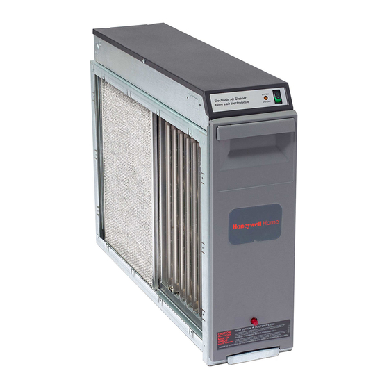
The high efficiency F50F Electronic Air
Cleaner is mounted in the return air duct of a
forced air heating, cooling, or ventilating sys-
tem. It removes airborne particles such as dust,
soot, pollen, tobacco smoke and cooking smoke
from the air circulated through it.
Available in four sizes to fit most ducts; adapts to
air flow from either side.
Has one or two cells, depending on cabinet size.
Capacity varies from 1000 cfm [1700 m
3
2000 cfm [3400 m
/hr], depending on size.
Up to 95 percent efficient (16 x 25 in. model at
500 cfm), measured by National Bureau of Stan-
dards Dust Spot Method using atmospheric dust,
and American Society of Heating, Refrigerating,
and Air-Conditioning Engineers Standard 52-76.
Solid state power supply is self-regulating and
maintains peak efficiency during a wide range of
cell dirt loading conditions.
Pressure drop is approximately equal to that of a
regular fiberglass filter.
Optional W8600E Solid State Performance Indi-
cator monitors air cleaner performance, reminds
homeowner when a cell and prefilter wash is past
due, and when to check the system.
J.H. • Rev. 5-94 • ©Honeywell Inc. 1994 • Printed in U.S.A. • Form Number 68-0137B—2
Electronic Air Cleaner
3
/hr] to
CONTENTS
1
Duct Mounted
Electronic cell(s) can be washed in most home
dishwashers.
Galvanized cabinet protects against rust.
Neon light next to on-off switch tells if air cleaner
is powered and if high voltage is present.
Test button checks system operation.
Troubleshooting guide mounted inside cell ac-
cess door.
Permanent wash reminder schedule included for
mounting in convenient location.
Prefilter screen(s) protect cell(s) from large dirt
particles.
Specifications ................................................. 2
Ordering Information ..................................... 2
Planning the Installation ................................ 4
Installation ..................................................... 7
Operation ..................................................... 12
Checkout ....................................................... 12
Service .......................................................... 13
Electrical Troubleshooting ........................... 17
Replacement Parts/Exploded View .............. 19
F50F
68-0137B—2
Advertisement
Table of Contents

Related Manuals for Honeywell F50F


Summary of Contents for Honeywell F50F
- Page 1 Planning the Installation ........ 4 Installation ............. 7 Operation ............. 12 Checkout ............12 Service ............13 Electrical Troubleshooting ......17 Replacement Parts/Exploded View ....19 J.H. • Rev. 5-94 • ©Honeywell Inc. 1994 • Printed in U.S.A. • Form Number 68-0137B—2 68-0137B—2...
-
Page 2: Specifications
If you have additional questions, need further information, or would like to comment on our products or services, please write or phone: 1. Your local Honeywell Home and Building Control Sales Office (Check White Pages of your phone directory). 2. Home and Building Control Customer Satisfaction Honeywell Inc., 1885 Douglas Drive North... -
Page 3: And Air-Conditioning Engineers Standard
F50F SPECIFICATIONS Fig. 1—Air cleaner efficiency and pressure drop at various airflow rates. [62.2] [49.7] 20 x 25 in. 16 x 25 in. [508 x 635 mm] [406 x 635 mm] [37.3] 20 x 20 in. 20 x 12-1/2 in. -
Page 4: Planning The Installation
Planning the Installation APPLICATION IMPORTANT: Do not mount in the discharge air duct. The F50F is used in a forced air heating, cooling, or ventilating system. It removes airborne particles such as For most efficient air cleaning, airflow must be spread dust, soot, pollen, tobacco smoke and cooking smoke evenly across the face of the air cleaner. - Page 5 Optional W8600E hard water salts will be blown into the living space and The F50F terminal board is recessed slightly so it or the deposited as dust. If an atomizing humidifier must be wires will not interfere with installation. The entire power...
- Page 6 F50F PLANNING THE INSTALLATION — Downflow “Counterflow” furnace: Air cleaner is — High capacity system: Two or more air cleaners can mounted horizontally in return duct or plenum just be used together. See Fig. 3F. above furnace. See Fig. 3E.
- Page 7 F50F PLANNING THE INSTALLATION • INSTALLATION Turning Vanes If the air cleaner is installed close to an elbow or angle Fig. 5—Typical use of duct offset to allow space fitting, install turning vanes inside the angle to distribute for electronic air cleaner.
- Page 8 TURNING VANES LOCKING PLIERS M3677 M3678 Fig. 8—Schematic for wiring W8600E to F50F. W8600E INSTALL TURNING VANES Mount turning vanes inside the elbow or angle fitting that is directly against the air cleaner cabinet. TERMINAL STRIP FASTEN CABINET TO DUCTWORK...
- Page 9 F50F INSTALLATION Remove the W8600E base and drill the holes. Install the SEAL JOINTS anchors and screws so the base is mounted firmly on the Seal all joints in the return air system between the air wall at the correct distance from the T8600.
- Page 10 F50F INSTALLATION 3. Turn the key around and place it over the opposite Replace the access door. Insert the tab on the bottom of holes. The tab on the bottom fits into the larger hole, and the the door into the slot in the cabinet, then swing it closed and screw fits into the smaller hole.
- Page 11 F50F INSTALLATION Fig. 14—Internal schematic for electronic air cleaner with W8600E. BLACK COLLECTOR TEST RED IONIZER BUTTON CONTACT BOARD BLACK BLACK POWER SUPPLY BLACK ORANGE GREEN GRAY BROWN VIOLET TERMINAL STRIP BLACK FRONT BACK BLACK W8600E WALL PANEL BLACK BLACK AIR FLOW SWITCH BOARD 1 INTERLOCK SWITCH.
-
Page 12: Operation
The air leaving the air cleaner has fewer particles. are given an electrical charge. The air then moves through Each time the air circulates through the F50F, more par- the collector part of the cell where alternate parallel plates ticles are removed. -
Page 13: Service
F50F SERVICE Service IMPORTANT: CAUTION • Check the dishwasher owner’s manual. Some manu- facturers do not recommend washing electronic SHARP EDGES. cell(s) in their dishwashers. CAN CAUSE PERSONAL INJURY. • If the dishwasher has upper and lower arms, position Carefully handle the cell(s) or wear protective the cell(s) carefully to allow good water circulation. - Page 14 M677B Reinstall the Cell(s) and Prefilter(s) 1. Inspect the cell(s) for broken ionizer wires and bent collector plates. Repair as necessary or take to a Honeywell Authorized Air Cleaner Repair Station. 2. Slide the prefilter(s) into the upstream prefilter guides.
- Page 15 F50F SERVICE REPLACING IONIZER WIRES Broken or bent ionizer wires can cause an electrical Fig. 20—Use ohmmeter to check electronic cells for short circuits. short to ground, often resulting in visible arcing or spark- ing. Do not use cell(s) until broken wires are removed.
- Page 16 F50F SERVICE Fig. 21—Remove power box from air cleaner and remove the cover. M6168 Fig. 22—Clip out J2 jumper to reduce ozone 2. Clip out the J2 jumper on the power supply. This will production about 20 to 25 percent.
-
Page 17: Electrical Troubleshooting
F50F SERVICE • ELECTRICAL TROUBLESHOOTING when the collector section is clean. The sensitivity to trig- To reduce the WASH LED sensitivity: ger the WASH LED can be reduced so the time between 1. Unplug or disconnect power to the air cleaner. - Page 18 F50F ELECTRICAL TROUBLESHOOTING Fig. 23—Troubleshooting air cleaners with solid-state performance indicator. START TO USE THIS CHART: FOLLOW THE STEPS IN ORDER, DO NOT SKIP AROUND. EACH TIME YOU ISOLATE AND FIX A PROBLEM, GO BACK TO START. REPEAT ALL THE STEPS UNTIL THE AIR CLEANER CHECKS OUT OK.
-
Page 19: Replacement Parts/Exploded View
F50F REPLACEMENT PARTS/EXPLODED VIEW Replacement Parts/Exploded View Nominal Return Air Opening 16 x 25 in. 20 x 25 in. 20 x 12-1/2 in. 20 x 20 in. Description [406 x 635 mm] [508 x 635 mm] [508 x 318 mm] [508 x 508 mm]... - Page 20 F50F REPLACEMENT PARTS/EXPLODED VIEW Fig. 24—Components of the F50F Electronic Air Cleaner (2-cell model shown). M3751 Home and Building Control Home and Building Control Helping You Control Your World Honeywell Inc. Honeywell Limited—Honeywell Limitée 1985 Douglas Drive North 740 Ellesmere Road...
-
Page 21: Table Of Contents
Vérification ..........12 vérification du filtre est nécessaire. Maintenance ..........13 Vérification du fonctionnement électrique .. 17 Liste des pièces ..........19 J.H. • Rev. 5-94 • ©Honeywell Inc. 1994 • Imprimé aux États-Unis • N de publication 68-0137B—2 68-0137B—2... -
Page 22: Fiche Technique
5. S’il y a lieu l’indicateur d’état à semi-conducteurs W8600E. Adresser toute question, demande de renseignements ou observation concernant nos produits et services par écrit ou par téléphone 1. Bureau des ventes de la Régulation résidentielle et commerciale de Honeywell de votre région (Consulter l’annuaire téléphonique). - Page 23 F50F FICHE TECHNIQUE Fig. 1—Efficacité et chute de pression du filtre à air à différents débits. 62.2. [.25] 49.7 [.20] 508 x 635 mm 406 x 635 mm 37.3 [20 x 25 in.] [16 x 25 in.] [.15] 508 x 508 mm [20 x 20 in.]...
-
Page 24: Planification De L'installation
APPLICATION Pour que le nettoyage de l’air soit plus efficace, le Le filtre à air électronique à haut rendement F50F débit d’air doit être égal à la surface du filtre. Si la gaine s’installe dans la gaine de reprise d’air dans un système n’a pas le même encombrement que le boîtier du filtre à... - Page 25 Ajout du W8600E optionnel humidificateur en amont du filtre à air: Le bornier du F50F est un peu en retrait pour que la 1. L’installer le plus loin possible en amont du filtre à air. plaque à bornes ou les fils n’entravent pas à l’installation.
- Page 26 F50F PLANIFICATION DE L’INSTALLATION la verticale sur l’appareil de chauffage entre de reprise d’air ou le plénum juste au-dessus de celui-ci et l’orifice à fentes pour l’air repris dans la l’appareil de chauffage. Voir fig. 3E. porte du placard. Voir fig. 3C.
-
Page 27: Installation
F50F PLANIFICATION DE L’INSTALLATION • INSTALLATION Déflecteurs Si le filtre à air est installé près d’un coude ou d’un Fig. 5—Utilisation typique du raccord de raccord d’équerre, installer les déflecteurs à l’intérieur du dérivation de la gaine pour donner de l’espace au filtre à... - Page 28 F50F INSTALLATION Fig. 6—Fixer le boîtier à l’appareil de chauffage. Fig. 7—Raccorder le système de gaine au filtre à air. Remarquer l’emplacement des déflecteurs. Une pince-étau fixe la gaine au boîtier du filtre à air pendant l’installation. DÉFLECTEURS PINCE-ÉTAU MF3677 Fig.
- Page 29 F50F INSTALLATION Tenir la plaque de montage du W8600E près du SCELLER LES JOINTS gabarit et marquer les trous pour les chevilles d’ancrage Sceller tous les joints du système de reprise d’air entre des vis et pour l’insertion du câble quadrifilaire du le filtre à...
- Page 30 à l’intérieur de la porte d’accès. cellule doit pointer en aval. Brancher le F50F directement à la boîte de sortie. Le 2. Tenir la poignée par les côtés et insérer la languette F50F fonctionnera bien peu importe la vitesse du derrière la poignée dans la fente de la cellule.
- Page 31 F50F INSTALLATION Fig. 14—Schéma de raccordement interne du F50F au W8600E. COLLECTEUR NOIR BOUTON IONISATEUR ROUGE D’ESSAI ROUGE PANNEAU DE CONTACT NOIR NOIR ALIMENTATION NOIR ORANGE VERT GRIS BRUN VIOLET BORNIER NOIR DEVANT DERRIÈRE NOIR VERS LE TABLEAU MURAL DU...
-
Page 32: Fonctionnement
À la sortie du filtre à air, l’air propre contient très peu de fils ionisants. Toutes les particules reçoivent une particules. Chaque fois que l’air circule dans le F50F, la décharge électrique. L’air passe par ensuite dans les quantité de particules diminue. -
Page 33: Maintenance
F50F MAINTENANCE Maintenance Nettoyage de la (des) cellule(s) dans le lave-vaisselle AVERTISSEMENT AVERTISSEMENT EXTRÉMITÉS TRANCHANTES. PEUVENT CAUSER DES BLESSURES. DANGER DE BRÛLURE. Manipuler la (les) cellule(s) et le(s) préfiltre(s) PEUT CAUSER DES BLESSURES. avec soin afin d’éviter de se couper sur les Permettre aux cellules de refroidir entièrement... - Page 34 F50F MAINTENANCE 3. Essuyer les fils ionisants et la plaquette de contact rincer jusqu’à ce que l’eau qui s’écoule de la (des) au moyen d’un chiffon propre. cellule(s) ou du (des) préfiltre(s) ne soit plus glissante. 4. Vérifier le lave-vaisselle. Vous voudrez peut-être refaire le cycle de lavage ou de rinçage lorsque le lave-...
- Page 35 F50F MAINTENANCE 5. Mettre en marche le filtre à air. Si la (les) cellule(s) fig. 19. Prendre bien soin de ne pas endommager le et le(s) préfiltre(s) sont toujours humides, la lampe- connecteur à ressort ou toute autre pièce de la cellule.
- Page 36 F50F MAINTENANCE Fig. 21—Retirer le bloc d’alimentation du filtre à air pour enlever le couvercle. M6168 concentration de la plupart des grandes villes atteint Fig. 22—Couper le cavalier J2 pour réduire la production d’ozone d’environ 20 à 25 %. parfois 0,100 ppm. Toutefois, on peut réduire la quantité...
-
Page 37: Vérification Du Fonctionnement Électrique
F50F MAINTENANCE • VÉRIFICATION DU FONCTIONNEMENT ÉLECTRIQUE MODIFICATION À FAIRE POUR RÉDUIRE LA AVERTISSEMENT SENSIBILITÉ DU VOYANT WASH DU W8600E AVERTISSEMENT RISQUE DE CHOC ÉLECTRIQUE. PEUT CAUSER DES BLESSURES. RISQUE DE CHOC ÉLECTRIQUE. Seulement un technicien d’expérience devrait PEUT CAUSER DES BLESSURES. - Page 38 F50F VÉRIFICATION DU FONCTIONNEMENT ÉLECTRIQUE Fig. 23—Dépannage des filtres à air électroniques avec un indicateur d’état. VÉRIFICATION DES FILTRES À AIR AVEC INDICATEUR D’ÉTAT À SEMI-CONDUCTEURS W8600E ET INTERRUPTEUR À DÉBIT D’AIR DÉBUT POUR UTILISER CE DIAGRAMME : 1. Suivre les étapes dans l'ordre, ne pas sauter d'étape.
-
Page 39: Liste Des Pièces
F50F LISTE DES PIÈCES Liste des pièces Ouverture nominale de la reprise d’air 406 x 635 mm 508 x 635 mm 508 x 318 mm 508 x 508 mm Description (16 x 25 po) (20 x 25 po) (20 x 12-1/2 po) (20 x 20 po) Porte d’accès (comprend la pièce 2) - Page 40 F50F LISTE DES PIÈCES Fig. 24—Composants du filtre à air électronique F50F( Modèle à deux cellules). M3751 Groupe de la Régulation Résidentielle et Commerciale Pour la Maîtrise de Votre Univers Honeywell Limitée Honeywell Inc. 740 Ellesmere Road 1985 Douglas Drive North...
Need help?
Do you have a question about the F50F and is the answer not in the manual?
Questions and answers