Table of Contents
Advertisement
Quick Links
Download this manual
See also:
User Manual
Advertisement
Table of Contents

Related Manuals for QTech QSW-2900


Summary of Contents for QTech QSW-2900
- Page 1 QSW-2900 Ethernet Switch User’s Manual...
- Page 2 QSW-2900 Intelligent L2+ Switch Configuration Manual Accessing Switch Switch Management and Maintenance Port Configuration VLAN configuration Multicast Configuration DHCP Configuration ARP configuration ACL Configuration QOS Configuration 10. STP Configuration 11. 802.1X Configuration Command 12. SNTP Client Configuration 13. Syslog Configuration 14.
-
Page 3: Table Of Contents
Content Content Chapter 1 Accessing Switch......................1-11 Command Line Interface ....................1-11 1.1.1 Command Line Configuration Mode ..............1-11 1.1.2 Command Syntax Comprehension..............1-12 1.1.3 Syntax Help ....................... 1-13 1.1.4 History command ....................1-14 1.1.5 Symbols in command..................1-14 Command Symbols Description ..................1-14 1.2.1 Command Parameter Categories.............. - Page 4 2.4.3 Network connecting test command..............2-29 2.4.4 Loopback test command................... 2-30 2.4.5 Administration IP address restriction ..............2-30 2.4.6 The number of Telnet user restriction ............... 2-31 2.4.7 Routing tracert command.................. 2-31 2.4.8 cpu-car command ..................... 2-32 Monitor system by SNMP....................2-32 2.5.1 Brief introduction of SNMP................
- Page 5 3.2.8 Enable/disable VLAN filtration of receiving packet of interface......3-52 3.2.9 Interface ingress acceptable-frame configuration ..........3-52 3.2.10 Enable/disable interface flow-control..............3-52 3.2.11 Port mode configuration..................3-53 3.2.12 Trunk allowed VLAN configuration ..............3-53 3.2.13 The default vlan-id of trunk port configuration ..........3-53 3.2.14 Add access port to specified VLAN ..............
- Page 6 Port-Based and 802.1Q VLAN....................4-69 4.4.1 Port link type ..................... 4-69 4.4.2 Default VLAN ....................4-69 Policy-Based VLAN......................4-69 Super VLAN........................4-70 Isolate-User-VLAN ......................4-70 VLAN interface type ......................4-71 Default VLAN ........................4-71 4.10 VLAN configuration ......................4-71 4.10.1 VLAN configuration list..................4-71 4.10.2 Create/delete VLAN ..................4-72 4.10.3 Add/delete VLAN interface ................
- Page 7 GMRP Configuration ......................5-88 5.3.1 GMRP Configuration list ................... 5-88 5.3.2 Enable/disable global GMRP................5-88 5.3.3 Enable/disable GMRP on a port ............... 5-88 5.3.4 Display GMRP....................5-89 5.3.5 Add/delete multicast that can be dynamic learnt by GMRP ......5-89 5.3.6 Display multicast that can be learnt by GMRP ..........5-89 IGMP Snooping Configuration ....................5-90 5.4.1 IGMP Snooping Overview.................
- Page 8 DHCP Packet Processing Modes ..................6-107 Protocols and Standards ....................6-108 DHCP Relay Agent......................6-108 6.7.1 Usage of DHCP Relay Agent ................6-108 6.7.2 DHCP Relay Agent Fundamentals ..............6-108 6.7.3 Option 82 Supporting ..................6-109 DHCP relay Configuration list ................... 6-111 6.8.1 Enable DHCP relay..................6-111 6.8.2 Configure vlan interface ...................6-111...
- Page 9 8.3.5 Define layer 2 ACL ..................8-127 8.3.6 User-defined ACL.................... 8-128 8.3.7 Activate ACL....................8-129 Monitor and maintanence of ACL..................8-129 Chapter 9 QOS Configuration ......................9-131 Brief introduction of QOS ....................9-131 QOS Configuration......................9-133 9.2.1 QoS Configuration list ..................9-133 9.2.2 Packet redirection configuration ..............
- Page 10 10.4.2 Configure MSTP timer parameter..............10-159 10.4.3 Configure MSTP configuration mark............. 10-159 10.4.4 Configure MSTP netbridge priority ............... 10-160 10.4.5 Configure MSTP interface edge interface status.......... 10-160 10.4.6 Configure MSTP interface link type .............. 10-160 10.4.7 Configure MSTP interface path cost............. 10-160 10.4.8 Configure MSTP interface priority..............
- Page 11 Chapter 15 LLDP configuration ...................... 15-182 15.1 Brief introduction of LLDP protocol .................15-182 15.2 Introduction to LLDP ......................15-182 15.2.1 LLDP Overview ..................... 15-182 15.3 LLDP configuration......................15-183 15.3.1 LLDP configuration list .................. 15-183 15.3.2 Enable/disable global LLDP................15-183 15.3.3 Configure LLDP hello-time................15-183 15.3.4 Configure LLDP hold-time................
- Page 12 17.2.1 PPPoE Plus Configuration list ..............17-197 17.2.2 Enable/disable PPPoE Plus................17-197 17.2.3 Configure PPPoE Plus type ................17-198 Chapter 18 CFM Configuration ...................... 18-199 18.1 Brief introduction of CFM....................18-199 18.2 Connectivity fault management overview................18-199 18.3 Basic Concepts in Connectivity Fault Detection ..............18-199 18.3.1 Maintenance domain..................
-
Page 13: Chapter 1 Accessing Switch
Accessing Switch Chapter 1 This chapter is the basic knowledge for system management, including: · Command line interface · Command syntax comprehension · Syntax help · History command · Symbols in command · Parameter in command · User management · Ways for switch management Command Line Interface System provides a series of configuration command and command line interface. -
Page 14: Command Syntax Comprehension
Table 1. Command Line Configuration Mode Command line Function Prompt Command for entering Command for exiting mode character User mode See switch QTECH> Connect with switch after exit disconnect with switch operation inputting user name and information password Privileged mode See switch QTECH#... -
Page 15: Syntax Help
“quit” is a command without parameter. The name of the command is quit. Press enter button after inputting it to execute this command. ! User need input parameter QTECH(config)#vlan 3 “vlan 3”is a command with parameter and keyword, vlan of which is command keyword and 3 of which is parameter. -
Page 16: History Command
<enter> The command end. · Parameter range and form QTECH(config)#spanning-tree forward-time ? INTEGER<4-30> switch delaytime: <4-30>(second) · Command line end prompt QTECH(config)#spanning-tree ? <enter> The command end. 1.1.4 History command Command line interface will save history command inputted by user automatically so that user can invoke history command saved by command line interface and re-execute it. -
Page 17: Command Parameter Categories
1.2.1 Command Parameter Categories There are 5 categories command parameter as following: · Scale Two numerical value linked by hyphen in angle brackets (< >) means this parameter is some number in the range of those two numbers. For example: INTEGER<1-10>... -
Page 18: System Default User Name
If the privilege doesn’t configure, the default privilege is ordinary user. At most 8 users are supported. Caution: User name supports case insensitivity while password doesn’t support case sensitivity. ! Add a new administrator “red”, configure privilege to be 3, and password to be 1234 QTECH(config)#username red privilege 3 password 0 1234 1.3.3 Modify password In global configuration mode, system administrator admin can use the following command to modify password of his or other user. -
Page 19: Modify Privilege
For example: ! Modify the privilege of administrator “red” to be 1, and password to be 1234 QTECH(config)#username red privilege 1 password 0 1234 1.3.5 Remove user name System administrator admin can use following command to remove user name in global configuration mode no username username Username is the user name to be deleted. -
Page 20: Remote Authentication Of Administrator
____________________________________________________________ ADMIN Remote authentication of administrator After authentication, user’s default privilege is normal user. Only when there is Service-Type field in authentication accepting packet the value of which is Administrative, user’s privilege is administrator. Caution: Admin user only supports local database authentication. 1.4.1 Start RADIUS remote authentication Use following command in globa configuration mode:... -
Page 21: Manage Switch By Telnet
Step 4: After successfully logging in, following information is displayed: QTECH> Step 5: As administrator, after entering privileged mode, use copy running-config startup-config command to save configuration. QTECH#copy running-config startup-config When following information is displayed: Startup config in flash will be updated, are you sure(y/n)? [n]y Building, please wait... - Page 22 Step 5: If you want to exit telnet, use quit or exit command to exit in user mode, and quit command to exit in other mode. Administrator can use stop username command in privileged mode to exit logging in. 1-20...
-
Page 23: Switch Manage And Maintenance
…, in which “xxxx” means the line number of the command, and commandString means command character string. Un-executive command includes command with grammar fault and un-matching pattern. Use following command in privileged mode. QTECH#copy running-config startup-config 2.1.3 Erase configuration clear startup-config command to clear saved configuration. -
Page 24: Display Current Configuration
! Display all saved configuration QTECH#show running-config ! Display saved configuration of GARP and OAM module QTECH#show running-config garp oam 2.1.6 Display current configuration User can display syatem current configuration information in the form of text by command line interface. Use... -
Page 25: Upload And Download Files By Tftp
For example: ! Upload configuration to 192.168.0.100 by FTP and saved as abc QTECH#upload configuration ftp 192.168.0.100 abc username password Configuration information saved when uploading is successful. ! Download configuration program abc to 192.168.0.100 by TFTP QTECH#load configuration ftp 192.168.0.100 abc... -
Page 26: Download Files By Xmodem
QTECH#upload configuration ftp 192.168.0.100 abc user 1234 Configuration information saved when uploading is successful. ! Download configuration program abc to 192.168.0.100 by FTP QTECH#load configuration ftp 192.168.0.100 abc user 1234 Reboot the switch after successful download and run new configuration program. -
Page 27: Mac Address Table Management
300 seconds. Disable means MAC address not aging. Use no command to restore the default MAC address aging time. For example: ! Configure MAC address aging time to be 3600 seconds QTECH(config)#mac-address-table age-time 3600 ! Restore MAC address aging time to be 300 seconds QTECH(config)#no mac-address-table age-time Display MAC address aging time... -
Page 28: Configure Mac Address Item
For example: ! Add mac address 00:01:02:03:04:05 to be static address table. QTECH(config)#mac-address-table static 00:01:02:03:04:05 interface ethernet 0/1 vlan 1 b) Add blackhole MAC address System can configure MAC address table item to be blackhole item. When the source address or destination address is blackhole MAC address, it will be dropped. - Page 29 It will be effective after rebooting. mac-address-table learning mode { svl | ivl } show mac-address-table learning mode For example: ! Modify MAC address to be IVL QTECH(config)#mac-address-table learning mode ivl ! Display MAC address learning mode. QTECH(config)#show mac-address-table learning mode 2-27...
-
Page 30: Reboot
Display cpu information For example: ! Display system version QTECH>show version software platform : Broadband NetWork Platform Software software version : QTECH QSW-2900 V100R001B01D001P001SP5 copyright : Copyright (c) 2001-2007 compiled time : Apr 09 2008 20:30:00 processor : ARM9, 180MHz... -
Page 31: Basic Configuration And Management
1 to 32, these strings can be printable, excluding such wildcards as '/', ':', '*', '?', '\\', '<', '>', '|', '"'etc. Use no hostname command in global configuration mode to restore default host name to be QTECH. For example:... -
Page 32: Loopback Test Command
Loopback on specified interface: loopback { external | internal } External means external loopback and internal means internal loopback For example: ! Loopback on interface Ethernet 0/1 QTECH(config-if-ethernet-0/1)#loopback external ! Loopback on all interfaces QTECH(config)#loopback internal 2.4.5 Administration IP address restriction Managed ip address restriction can restrict host IP address or some network interface of switch by restricting web, telnet and snmp agent, but other IP address without configuration cannot manage switch. -
Page 33: The Number Of Telnet User Restriction
For example: ! Configure ip address allowed by telnet management system to be 192.168.0.0/255.255.0.0 QTECH(config)#login-access-list telnet 192.168.0.0 0.0.255.255 QTECH(config)#no login-access-list telnet 0.0.0.0 255.255.255.255 Use show login-access-list command to display all ip address allowed by web, snmp, telnet management system. show login-access-list 2.4.6... -
Page 34: Cpu-Car Command
Response packet, and return it to NMS. On the other hand, the Trap packet of abnormity of cold boot or hot boot of devices will send to NMS. QTECH company is present it own QTECH NMS and Agent server. Please refer to the http://www.qtech.ru/support/software.htm System supports SNMP version of v1, v2c and v3. -
Page 35: Snmp Mechanism
information, find and diagnose network problems, plan for network growth, and generate reports on network nodes. · SNMP shields the physical differences between various devices and thus realizes automatic management of products from different manufacturers. Offering only the basic set of functions, SNMP makes the management tasks independent of both the physical features of the managed devices and the underlying networking technology. -
Page 36: Configuration
Figure 1 MIB tree Configuration SNMP configuration command list includes: · Configure community · Configure sysContact · Configure Trap destination host adress · Configure sysLocation · Configure sysName · Configure notify · Configure engine id · Configure view · Configure group ·... -
Page 37: Configure Syscontact
1 to 255 printable characters. Use the no command to restore default way of contacting to administrator. For example: ! Configure administrator contact way to be support@qtech.ru QTECH(config)#snmp-server contact support@qtech.ru Caution: Use quotation mark to quote space in charater string. -
Page 38: Configure Syslocation
Sysname means the charater string of system name ranges from 1 to 255 printable characters. For example: ! Configure system name to be QSW-2900 QTECH(config)#snmp-server name "QSW-2900" Caution: Use quotation mark to quote space in charater string. -
Page 39: Configure Notify
QTECH(config)# snmp-server engineid local 12345 ! Configure remote engine that can be recognized locally. Configure remote engine ip to be 1.1.1.1, and port number to be 888, and id to be 1234 QTECH(config)# snmp-server engineid remote 1.1.1.1 udp-port 888 1234 2-37... -
Page 40: Configure View
For example: ! Add view “view1”, and configure it to have a subtree “1.3.6.1” QTECH(config)# snmp-server view view1 1.3.6.1 include ! Add a subtree “1.3.6.2” for existed view “view1” QTECH(config)# snmp-server view view1 1.3.6.2 include ! Remove existed view “view1”... -
Page 41: Configure User
! Add group “group1” to local facility, using security model 1, and configure read, write, and notify view to be internet QTECH(config)# snmp-server group group1 1 read internet write internet notify Internet ! Remove group “group1” from local facility QTECH(config)# no snmp-server group group1 1 ! Display current group configuration. -
Page 42: 2.10 System Ip Configuration
! Add user “user3” for local engine to group “grp3”, and configure this user to use md5 authentication and des encryption with the auth-password to be 1234 and privpassword to be 4321 QTECH(config)# snmp-server user user3 grp3 auth md5 auth-password 1234 priv des priv-password 4321 2.10 System IP configuration... -
Page 43: Bootp
Enable BOOTP to obtainn IP address QTECH(config)#bootp Disable BOOTP to obtainn IP address QTECH(config)#no bootp Manual configuration QTECH(config)#ipaddress 192.168.0.100 255.255.0.0 192.168.0.254 2.10.5 Display ip address Use show ip command in any configuration mode to display ip address and its obtaining mode, netmask, and gateway:... -
Page 44: 2.11 Enable/Disable Dlf Forword Packet
Use no dlf-forward command to disable dlf forward: dlf-forward { multicast | unicast } no dlf-forward { multicast | unicast } For example: ! Disable dlf forward for unicast QTECH(config)#no dlf-forward unicast ! Disable dlf forward for multicast QTECH(config)#no dlf-forward multicast 2.12 CPU Alarm Configuration 2.12.1 Brief introduction of CPU alarm System can monitor CPU usage. -
Page 45: Enable/Disable Cpu Alarm
> unbusy. Default CPU busy threshold is 90%, and CPU unbusy threshold is 60%. For example: ! Configure CPU busy threshold to be 30%, and CPU unbusy threshold to be 10% QTECH(config)#alarm cpu threshold busy 30 unbusy 10 2.12.5 Display CPU alarm information... -
Page 46: 2.13 Anti-Dos Attack
2.13 Anti-DOS Attack 2.13.1 IP segment anti-attack The IP segment packet number which can be received by system do not occupy resources of all receiving packets, which can normally handle other non-segment packets when receiving IP segment attack and the range of IP segment receiving number can be configured. -
Page 47: Chapter 3 Port Configuration
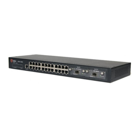
Port Configuration Chapter 3 Port configuration introduction System can provide 24 10/100Base-T Ethernet interfaces, 2 1000Base-TX(LX/SX) Ethernet interfaces and a Console interface. Ethernet interface can work in half duplex and full duplex mode, and can negotiate other working mode and speed rate with other network devices to option the best working mode and speed rate automatically to predigest system configuration and management. - Page 48 Figure 1. Host A sends an Ethernet frame to Host B on LAN segment 1 As the bridge receives the Ethernet frame on bridge interface 1, it determines that Host A is attached to bridge interface 1 and creates a mapping between the MAC address of Host A and bridge interface 1 in its bridge table, as shown in Figure 2.
- Page 49 Figure 3 The bridge determines that Host B is also attached to interface 1 Finally, the bridge obtains all the MAC-interface mappings (assume that all hosts are in use), as shown in Figure 4. Figure 4 The final bridge table b) Forwarding and filtering The bridge makes data forwarding or filtering decisions based on the following scenarios: When Host A sends an Ethernet frame to Host C, the bridge searches its bridge table and finds out that Host C...
- Page 50 Figure 5 Forwarding When Host A sends an Ethernet frame to Host B, as Host B is on the same LAN segment with Host A, the bridge filters the Ethernet frame instead of forwarding it, as shown in II. Figure 6. Figure 6 Filtering When Host A sends an Ethernet frame to Host C, if the bridge does not find a MAC-to-interface mapping about Host C in its bridge table, the bridge forwards the Ethernet frame to all interfaces except the interface on which the frame...
-
Page 51: Port Configuration
Figure 7 The proper MAC-to-interface mapping is not found in the bridge table Note: & When a bridge receives a broadcast or multicast frame, it forwards the frame to all interfaces other than the receiving interface. Port Configuration 3.2.1 Port related configuration Configure related feature parameter of ports should enter interface configuration mode first, and then configure. -
Page 52: Enter Interface Configuration Mode
Shutdown means disable a port, while no shutdown means enable a port. For example: ! Enable Ethernet interface 1 QTECH(config-if-ethernet-0/1)#no shutdown ! Disable Ethernet interface 25 QTECH(config-if-ethernet-1/1)#shutdown When interface is shutdown, the physical link is working for diagnosis. -
Page 53: Interface Prioruty Configuration
! Configure description string “red” for the Ethernet 0/3 QTECH(config-if-ethernet-0/3)#description red ! Display description of Ethernet 0/3 QTECH(config)#show description interface ethernet 0/3 3.2.7 Ingress/egress bandwidth-control configuration Egress/ingress bandwidth-control is to restrict the total speed rate of all sending and receiving packets. -
Page 54: Enable/Disable Vlan Filtration Of Receiving Packet Of Interface
Example: ! Enable VLAN ingress filtration of e0/5 QTECH(config-if-ethernet-0/5)#ingress filtering ! Disable VLAN ingress filtration of e0/5 QTECH(config-if-ethernet-0/5)#no ingress filtering 3.2.9 Interface ingress acceptable-frame configuration Configure ingress acceptable frame mode to be all types or only tagged. Use following command in interface configuration mode to configure or cancel the restriction to ingress... -
Page 55: Port Mode Configuration
For example: ! Add trunk ports Ethernet0/1 to VLAN 3, 4, 70 to 150 QTECH(config-if-ethernet-0/1)# switchport trunk allowed vlan 3, 4, 70- 150 3.2.13 The default vlan-id of trunk port configuration Use switchport trunk native vlan command to configure the default vlan-id (pvid) of trunk port. When receiving untagged packet, it will be transferred to VLAN defaulted VLAN ID. -
Page 56: Add Access Port To Specified Vlan
3.2.14 Add access port to specified VLAN Use switchport access command to add access port to specified VLAN, and the default VLAN-ID is configured to be the specified VLAN. Configure it in interface configuration mode: Add current port to specified VLAN, and the default VLAN-ID is configured to be the specified VLAN switchport access vlan vlan-id Remove current port from specified VLAN, if the default vlan-id of the current port is the specified VLAN and this port also belongs to VLAN 1, the default vlan-id of the current port restores to be 1, or the default VLAN ID... -
Page 57: Interface Mirror
{ interface-list | cpu } For example: ! Configure Ethernet 0/1 to Ethernet 0/12 to be mirror source interfaces QTECH(config)# mirror source-interface ethernet 0/1 to ethernet 0/12 both ! Remove Ethernet 0/10 to Ethernet 0/12 from mirror source interfaces 3-55... -
Page 58: Port Lacp Convergent Configuration
QTECH(config)#no mirror source-interface ethernet 0/10 to ethernet 0/12 c) Display interface mirror Use show mirror command to display system configuration of current mirror interface, including monitor port and mirrored port list. Use this command in any configuration mode: show mirror... -
Page 59: Lacp
the current channel grou. If transferring to other channel group, only one packet will be transferred. If there are members in the channel group, this channel group cannot be deleted. Delete interface members first. Influence on choosing link redundancy caused by LACP system and interface priority. LACP provides link redundancy mechanism which needs to guarantee the redundancy consistency of two interconnected switches and user can configure redundancy link which is realized by system and interface priority. -
Page 60: Static Lacp Link Aggregation
· Place the ports that cannot aggregate with the master in unselected state, for example, as the result of the cross-board aggregation restriction. Manual aggregation limits the number of selected ports in an aggregation group. When the limit is exceeded, the system changes the state of selected ports with greater port numbers to unselected until the number of selected ports drops under the limit. -
Page 61: Load Sharing In A Link Aggregation Group
Parameter “channel-group-number” is range from 0 to 5. For example: ! Create a channel group with the group number being 0 QTECH(config)#channel-group 0 Delete channel group no channel-group channel-group-number Add add port members to the group channel-group channel-group-number mode {active | passive | on}... - Page 62 For example: ! Add Ethernet 0/3 to channel-group 3 and specify the port to be active mode QTECH(config-if-ethernet-0/3)#channel-group 3 mode active Delete interface member in channel group no channel-group channel-group-number In interface configuration mode, delete current interface from channel group.
-
Page 63: Interface Car Configuration
Use show lacp interval command to display the information of group members, if the there is no keywords, all groups are displayed. For example: Display the member information of channel group 2. QTECH#show lacp internal 2 Display information of neighbour interface of channel group show lacp neighbor [channel-group-number] Use show lacp neighbor command to display the information of the neighbour port in the group. -
Page 64: Enable/Disable Interface Car On Interface
Configure the reopen time of the port shutdown by port-car port-car-open-time time By default, port-car-open-time is 480 seconds For example: ! Configure port-car-open-time to be 10 seconds QTECH(config)#port-car-open-time 10 3.9.6 Configure the port-car-rate Please configure it in global configuration mode: Configure the port-car-rate... -
Page 65: 3.10 Port Alarm Configuration
For example: ! Display port-car information QTECH(config)#show port-car 3.10 Port Alarm Configuration 3.10.1 Brief introduction of port alarm configuration System can monitor port packet receiving rate. If the rate of receiving packet is beyond the interface flow exceed threshold, send alarm of large interface flow and the interface is in the status of large interface flow. In this status, if the rate of receiving packet is lower than the interface flow normal threshold, send alarm of normal interface flow. -
Page 66: Configure The Exceed Threshold And Normal Threshold Of Port Alarm
60 For example: ! Configure alarm all-packets exceed threshold to be 500, and normal threshold to be 300 QTECH(config)#alarm all-packets threshold exceed 500 normal 300 3.10.6 Display port alarm Input following command in any configuration mode to display global interface alarm:... -
Page 67: 3.11 Interface Shutdown-Control Configuration
[ broadcast | multicast | unicast ] By default, shutdown-control is disabled. Example: ! Enable shutdown-control of e0/8 for broadcast and speed rate is 100pps. QTECH(config-if-ethernet-0/8)#shutdown-control broadcast 100 3.11.4 Configure shutdown-control open-time Configure it in global configuration mode:... -
Page 68: Display Shutdown-Control
3.11.5 Display shutdown-control Configure it in any configuration mode: show shutdown-control Example: ! Display interface shutdown-control information QTECH(config)#show shutdown-control 3-66... -
Page 69: Chapter 4 Vlan Configuration
VLAN Configuration Chapter 4 Introduction to VLAN 4.1.1 VLAN Overview Ethernet is a network technology based on the Carrier Sense Multiple Access/Collision Detect (CSMA/CD) mechanism. As the medium is shared in an Ethernet, network performance may degrade as the number of hosts on the network is increasing. -
Page 70: Vlan Fundamental
4.1.2 VLAN Fundamental To enable packets being distinguished by the VLANs they belong to, a field used to identifying VLANs is added to packets. As common switches operate on Layer 2, they only process Layer 2 encapsulation information and the field thus needs to be inserted to the Layer 2 encapsulation information of packets. The format of the packets carrying the fields identifying VLANs is defined in IEEE 802.1Q, which is issued in 1999. -
Page 71: Vlan Interface
VLAN Interface VLAN interfaces are virtual interfaces used for communications between different VLANs. Each VLAN can have one VLAN interface. Packets of a VLAN can be forwarded on network layer through the corresponding VLAN interface. As each VLAN forms a broadcast domain, a VLAN can be an IP network segment and the VLAN interface can be the gateway to enable IP address-based Layer 3 forwarding. -
Page 72: Super Vlan
As illustrated in the following figure, the isolate-user-vlan function is enabled on Switch B. VLAN 10 is the isolate-user-VLAN, and VLAN 2, VLAN 5, and VLAN 8 are secondary VLANs that are mapped to VLAN 10 and are invisible to Switch A. QSW-3500 VLAN 10 QSW-2900 VLAN 2 VLAN 5 VLAN 8 4-70... -
Page 73: Vlan Interface Type
Figure 1 An isolate-user-vlan example VLAN interface type System supports IEEE 802.1Q which possesses two types of VLAN interfaces. One is tagged, and the other is untagged. Tagged interface can ad VLAN ID, priority and other VLAN information to the head of the packet which is out of the interface. -
Page 74: Create/Delete Vlan
For example: ! Add Ethernet 1, 3, 4, 5, 8 to current VLAN QTECH(config-if-vlan)#switchport ethernet 0/1 ethernet 0/3 to ethernet 0/5 ethernet 0/8 ! Remove Ethernet 3, 4, 5, 8 from current VLAN QTECH(config-if-vlan)#no switchport ethernet 0/3 to ethernet 0/5 ethernet 0/8 Command switchport access vlan and its no command can also add and delete port to or from VLAN. -
Page 75: Specify/Restore Vlan Description
2. For example: ! Configure default vlan-id of Ethernet interface 1 to be 2 QTECH(config-if-ethernet-0/1)#switchport mode access QTECH(config-if-ethernet-0/1)#switchport access vlan 2 switchport trunk native vlan Caution: To use vlan-id must guarantee the specified interface to be trunk, switchport access vlan and belongs to specified VLAN, and the VLAN ID is not 1. -
Page 76: Display Vlan Information
For example: ! Configure Ethernet interface 1 to send IEEE 802.1Q packet with tag VLAN 5, VLAN 7-10 QTECH(config-if-ethernet-0/1)#tag vlan 5, 7-10 4.10.8 Display VLAN information VLAN information is VLAN description string, vlan-id, VLAN status and interface members in it, tagged interfaces, untagged interfaces and dynamic tagged interfaces. - Page 77 GARP itself does not exist on a device as an entity. GARP-compliant application entities are called GARP applications. One example is GVRP. When a GARP application entity is present on a port on your device, this port is regarded a GARP application entity. a) GARP messages and timers 1) GARP messages GARP participants exchange attributes primarily by sending the following three types of messages:...
- Page 78 c) GARP message format The following figure illustrates the GARP message format. Figure 1 GARP message format The following table describes the GARP message fields. Table 1 Description on the GARP message fields Field Description Value Protocol ID Protocol identifier for GARP Message One or multiple messages, each ––...
-
Page 79: Gvrp
Enable global GVRP gvrp Disable global GVRP no gvrp By default, GVRP globally disabled. For example: ! Enable GVRP globally QTECH(config)#gvrp 4.12.6 Enable/disable GVRP on a port Please configure it in interface configuration mode: Enable GVRP on a port 4-77... -
Page 80: Display Gvrp
Ethernet ports. If specified, the command displays GVRP information on specified Ethernet port. For example: ! Display GVRP information on interface Ethernet 0/1 QTECH(config)#show gvrp interface ethernet 0/1 4.12.8 Add/delete vlan that can be dynamic learnt by GVRP Use garp permit vlan command to add configured static vlan to GVRP module for other switches to learn. -
Page 81: Examples For Gvrp Configuration
Examples for GVRP configuration ! Enable GVRP on Ethernet port 2 QTECH(config-if-ethernet-0/2)#gvrp ! Disable GVRP on Ethernet port 2 QTECH(config-if-ethernet-0/2)#no gvrp 4.13 QinQ configuration 4.13.1 Brief introduction of QinQ QinQ is used for the commnunication between discrete client vlan whose service model is the interconnection of one or more switches supported QinQ by service provider interfaces which are in service provider vlan. -
Page 82: Implementations Of Qinq
· Provides a simple Layer 2 VPN solution for small-sized MANs or intranets. N ote: The QinQ feature requires configurations only on the service provider network, and not on the customer network. 4.13.3 Implementations of QinQ There are two types of QinQ implementations: basic QinQ and selective QinQ. 1) Basic QinQ Basic QinQ is a port-based feature, which is implemented through VLAN VPN. -
Page 83: Qinq Configuration List
4.13.6 Configure global QinQ QSW-2900 supports three QinQ: 1) Static QinQ. Vlan protocol number in this mode can be configured but cannot be configured to ignore tag head of ingress packet. If vlan protocol number is not the same as the port configuration value or the port is... -
Page 84: Configure Interface Dynamic Qinq
Delete all configured vlan tag packets to add a tag head with destination vlan3 from the start vlan1 to end vlan2. QTECH(config)#no dtag insert 1 2 3 3. Configure a series vlan to be transparent transmitted in dynamic QinQ in the form of start vlan. All vlan tag... -
Page 85: Configure Global Vlan-Swap
Example: Configure rewrite-outer-vlan of e0/1 with inner vlan ID being the range of 1~50, outer vlan ID being 3 and new outer vlan ID being 100 QTECH(config-if-ethernet-0/1)# rewrite-outer-vlan 1 50 outer-vlan 3 new-outer-vlan 100 4.13.12 Display dynamic QinQ 1. Display dynamic vlan... -
Page 86: Display Vlan-Swap
QTECH(config)#show dtag 2. Display transparent transmission vlan ! Command mode is global configuration mode show dtag pass-through Example: Display transparent transmission vlan QTECH(config)#show dtag pass-through 4.13.13 Display vlan-swap Display vlan swap status ! Command mode is global configuration mode show vlan-swap... -
Page 87: Chapter 5 Multicast Protocol Configuration
Multicast Protocol Configuration Chapter 5 Multicast overview 5.1.1 Multicast Address As receivers are multiple hosts in a multicast group, you should be concerned about the following questions: · What destination should the information source send the information to in the multicast mode? ·... - Page 88 Reserved multicast addresses (IP addresses for permanent multicast groups). The IP address 224.0.0.0 to 224.0.0.255 224.0.0.0 is reserved. Other IP addresses can be used by routing protocols. Available any-source multicast (ASM) multicast 224.0.1.0 to 231.255.255.255 addresses (IP addresses for temporary groups). 233.0.0.0 to 238.255.255.255 They are valid for the entire network.
-
Page 89: Gmrp Overview
different multicast domains, so that the same multicast address can be used in different multicast domains without causing collisions. b) Ethernet multicast MAC address When a unicast IP packet is transported in an Ethernet network, the destination MAC address is the MAC address of the receiver. -
Page 90: Gmrp Configuration
Disable global GMRP no gmrp By default, GMRP globally disables For example: ! Enable GMRP globally QTECH(config)#gmrp 5.3.3 Enable/disable GMRP on a port Enable global GMRP before enable GMRP on a port. Please configure it in interface configuration mode: ·... -
Page 91: Display Multicast That Can Be Learnt By Gmrp
Ethernet ports. If specified, the command displays GMRP information on specified Ethernet port. For example: ! Display GMRP information of Ethernet 0/2 to ethernet 0/4 ethernet 2/1 QTECH(config)#show gmrp interface ethernet 0/2 to ethernet 0/4 ethernet 2/1 port GMRP status e0/2 enable... -
Page 92: Igmp Snooping Configuration
IGMP Snooping Configuration 5.4.1 IGMP Snooping Overview Internet Group Management Protocol Snooping (IGMP Snooping) is a multicast constraining mechanism that runs on Layer 2 devices to manage and control multicast groups. By listening to and analyzing IGMP messages, a Layer 2 device running IGMP Snooping establishes mappings between ports and multicast MAC addresses and forwards multicast data based on these mappings. - Page 93 Figure 2 IGMP Snooping related ports Ports involved in IGMP Snooping, as shown in Figure 2, are described as follows: · Router port: A router port is a port on the Ethernet switch that leads switch towards the Layer 3 multicast device (DR or IGMP querier).
-
Page 94: How Igmp Snooping Works
Message before Timer Description Action after expiry expiry For each router IGMP general port, the switch query of which the Router port aging The switch removes this port sets a timer source address is timer initialized to the from its router port list. not 0.0.0.0 or PIM aging time of the hello... -
Page 95: Processing Of Multicast Protocol Messages
If a forwarding table entry exists for the reported group and the port is included in the outgoing port list, which means that this port is already a member port, the switch resets the member port aging timer for that port. &... - Page 96 2) In only PIM is enabled on the switch: The switch broadcasts IGMP messages as unknown messages in the VLAN. Upon receiving a PIM hello message, the switch will maintain the corresponding router port. 3) When IGMP is disabled on the switch, or when IGMP forwarding entries are cleared (by using the reset igmp group command): If PIM is disabled, the switch clears all its Layer 2 multicast entries and router ports.
- Page 97 Table 2-3 IGMP Snooping messages Message Sender Receiver Purpose Switch action IGMP Multicast Multicast Query if Check if the message comes from the If yes, reset the aging general router member original router port timer of the router port query switch multicast If not, notify the multicast...
-
Page 98: Protocols And Standards
Display IGMP Snooping Use following command in any mode to see IGMP Snooping: For example: ! Display IGMP snooping information QTECH(config)#show igmp-snooping 5.4.7 IGMP Snooping multicast interface aging time configuration Use following command in global configuration mode to configure host-aging-time dynamic multicast group... -
Page 99: Igmp Snooping Max-Response-Time Configuration
! Configure host-aging-time of the dynamic multicast group learnt by igmp-snooping to be 10 seconds QTECH(config)#igmp-snooping host-aging-time 10 5.4.8 IGMP Snooping max-response-time configuration Configure the max response time to delete group interface when receiving a leave packet: igmp-snooping max-response-time seconds Use this command in global configuration mode. -
Page 100: Igmp Snooping Route-Port Forward Configuration
Configure igmp-snooping default group learning regulation in global configuration mode: igmp-snooping deny/permit group all For example: ! Configure Ethernet 0/1 not to learn multicast 01:00:5e:00:01:01 QTECH(config-if-ethernet-0/1)#igmp-snooping deny group 01:00:5e:00:01:01 ! Configure the learning regulation of default group to allow all multicast group QTECH(config)#igmp-snooping permit group all 5.4.12... -
Page 101: Configure Igmp Snooping Querier Vlan
Example: ! Configure IGMP query source IP to be 1.1.1.111 QTECH(config)# igmp-snooping general-query source-ip 1.1.1.111 5.4.18 Configure IGMP Snooping route port aging The port receiving IGMP query is called multicast route port. -
Page 102: Add Igmp Snooping Route Port
Example: Configure e0/1 of vlan 2 to be route port of current group(determined by source IP of querie) QTECH(config)# igmp-snooping route-port vlan 2 interface ethernet 0/1 Static Multicast Configuration 5.5.1 Brief introduction of Static Multicast Static multicast configuration command is used to crewate multicast group and add interfaces to it. -
Page 103: Create Multicast Group
VLAN doesn’t exist, the multicast group adding fails. For example: ! Add interface Ethernet 0/2 to ethernet 0/4 ethernet 0/8 to existed multicast group QTECH(config)#multicast mac-address 01:00:5e:01:02:03 vlan 1 interface ethernet 0/2 to ethernet 0/4 ethernet 0/8 5.5.5 Display multicast group information... -
Page 104: Delete Interface Members From Multicast Group
All means all the members in multicast group. For example: ! Delete interface ethernet 5, 6 from existed multicast group. QTECH(config)#no multicast mac-address 01:00:5e:01:02:03 vlan 1 interface ethernet 0/5 ethernet 0/6 5.5.7... -
Page 105: Enable/Disable Cross-Vlan Multicast
Use this command to display cross vlan configuration and specified interface configuration. show cross-vlan multicast [interface] Example: ! Display configuration of cross vlan multicast of e0/1 QTECH(config)#show cross-vlan multicast interface ethernet 0/1 cross-vlan multicast : enabled. port tag vlanid 0/1 false 0 Total [1] item(s), printed [1] item(s). -
Page 106: Chapter 6 Dhcp Configuration
QTECH QSW-3500 or QSW-3900, a DHCP server is put in each VLAN. This is a greate waste of resources.A solution to this is to use the DHCP relay feature of QTECH QSW-2900, which relays DHCP messages to DHCP servers.Thus only one DHCP server is needed at least. -
Page 107: Dhcp Ip Address Assignment
Figure 1-1 Typical DHCP application DHCP IP Address Assignment 6.3.1 IP Address Assignment Policy Currently, DHCP provides the following three IP address assignment policies to meet the requirements of different clients: · Manual assignment. The administrator statically binds IP addresses to few clients with special uses (such as WWW server). -
Page 108: Updating Ip Address Lease
packet. 4) Acknowledge: Upon receiving the DHCP-REQUEST packet, the DHCP server returns a DHCP-ACK packet to the DHCP client to confirm the assignment of the IP address to the client, or returns a DHCP-NAK packet to refuse the assignment of the IP address to the client. When the client receives the DHCP-ACK packet, it broadcasts an ARP packet with the assigned IP address as the destination address to detect the assigned IP address, and uses the IP address only if it does not receive any response within a specified period. -
Page 109: Dhcp Packet Processing Modes
Figure 1-2 Format of DHCP packets The field meanings are illustrated as follows: · op: Operation types of DHCP packets: 1 for request packets and 2 for response packets. · htype, hlen: Hardware address type and length of the DHCP client. ·... -
Page 110: Protocols And Standards
server picks IP addresses from the interface address pools and assigns them to the DHCP clients. If there is no available IP address in the interface address pools, the DHCP server picks IP addresses from its global address pool that contains the interface address pool segment and assigns them to the DHCP clients. -
Page 111: Option 82 Supporting
Figure 3-1 Typical DHCP relay agent application DHCP relay agents can transparently transmit broadcast packets on DHCP clients or servers to the DHCP servers or clients in other network segments. In the process of dynamic IP address assignment through the DHCP relay agent, the DHCP client and DHCP server interoperate with each other in a similar way as they do without the DHCP relay agent. - Page 112 · Sub-option 1: A sub-option of option 82. Sub-option 1 represents the agent circuit ID, namely Circuit ID. It holds the port number and VLAN-ID of the switch port connected to the DHCP client, and is usually configured on the DHCP relay agent. Generally, sub-option 1 and sub-option 2 must be used together to identify information about a DHCP source.
-
Page 113: Dhcp Relay Configuration List
Configure specified VLAN for relaying DHCP packets. It MUST be the same VLAN, like the PVID of client’s port. Use for example this configuration for set the IP address of DHCP server and specify the interface VLAN aliase: QTECH(config)#vlan vlannumber QTECH(config-if-vlan)#interface ipaddress mask gateway QTECH(config-if-vlan)#dhcpserver ip ipadddress 6-111... -
Page 114: Dhcp Snooping
· Trusted ports forward any received DHCP packet to ensure that DHCP clients can obtain IP addresses from valid DHCP servers. Untrusted ports drop all the received packets. Figure 4-1 illustrates a typical network diagram for DHCP snooping application, where Switch A is an QSW-2900 series switch. -
Page 115: 6.10 Configuration Dhcp Snooping
Figure 4-2 Interaction between a DHCP client and a DHCP server DHCP snooping listens to the following two types of packets to retrieve the IP addresses the DHCP clients obtain from DHCP servers and the MAC addresses of the DHCP clients: ·... -
Page 116: Configure Ip Source Guard
6.10.4 Configure IP source guard Prevent IP address stolen through IP source guard. Configure interface IP source guard ip-source-guard 6.10.5 Show DHCP snooping of ports DHCP snooping of ports configuraton can be displayed by this command. Show DHCP snooping configuration of ports show dhcp-snooping interface [ interface-num ] 6.10.6 Show DHCP snooping configuration of VLANs... -
Page 117: Chapter 7 Arp Configuration (Dynamic Arp Inspection)
Display ARP table item Use this command to display static, dynamic, specified IP address or all ARP table item. Display all ARP table item: QTECH(config)#show arp all Display dynamic ARP table item: QTECH(config)#show arp dynamic Display static ARP table item:... -
Page 118: Enable/Disable Arp Anti-Flood Attack
Threshold range is from 1-100 pps. By default, the deny action is deny-arp and threshold is 16 pps. Example: ! Configure deny action to be all packets deny and threshold to be 10 pps QTECH(config)#arp anti-flood action deny-all threshold 10 7.2.4 Configure ARP anti-flood recover-time... -
Page 119: Arp Anti-Flood Mac Recover
The recover time can be configured in the range of 0-1440 minutes. If time is 0,it means never auto-recover. Example: ! Configure recover time to be 20 minutes QTECH(config)#arp anti-flood recover-time 20 Default recover time is 10 minutes. 7.2.5 ARP anti-flood MAC recover The banned MAC can auto-recover after recover time and specified and all banned MAC can cover manually. -
Page 120: Enable/Disable Arp Anti-Spoofing
(decompiling) : arp anti-flood bind blackhole { mac | all } For example: ! Bind mac:00:0a:5a:00:02:02 QTECH(config)#arp anti-flood bind blackhole 00:0a:5a:00:02:02 ! Bind all blackhole mac generated by all arp anti-flood QTECH(config)#arp anti-flood bind blackhole all 7.2.8 Enable/disable ARP anti-spoofing ARP anti-spoofing is used to check the match of ARP packet and configured static ARP. -
Page 121: Enable/Disable Arp Anti-Spoofing Valid-Check
Enable ARP anti-spoofing valid-check: QTECH(config)#arp anti-spoofing valid-check Disable ARP anti-spoofing valid-check: QTECH(config)#no arp anti-spoofing valid-check 7.2.11 Enable/disable ARP anti-spoofing deny-disguiser ARP gateway disguiser means attacker disguising gateway address to send free ARP packet whose gateway address is source IP address in LAN. -
Page 122: Configure Trust Port Of Arp Anti-Attack
7.2.13 Configure trust port of ARP anti-attack Use this command to set the port to be trust and ARP packet from this port will not be check attacking and spoofing. !Configure e0/1 to be trust QTECH(config-if-ethernet-0/1)#arp anti trust 7-120... -
Page 123: Chapter 8 Acl Configuration
ACL Configuration Chapter 8 ACL Overview An access control list (ACL) is used primarily to identify traffic flows. In order to filter data packets, a series of match rules must be configured on the network device to identify the packets to be filtered. After the specific packets are identified, and based on the predefined policy, the network device can permit/prohibit the corresponding packets to pass. -
Page 124: Ways To Apply Acl On A Switch
the higher the priority. 4) Range of Layer 4 port number, that is, of TCP/UDP port number. The smaller the range, the higher the priority. If rule A and rule B are the same in all the four ACEs (access control elements) above, and also in their numbers of other ACEs to be considered in deciding their priority order, weighting principles will be used in deciding their priority order. -
Page 125: Configuring Acl
ranges. A time range can be specified in each rule in an ACL. If the time range specified in a rule is not configured, the system will give a prompt message and allow such a rule to be successfully created. However, the rule does not take effect immediately. -
Page 126: Acl Configuration
Table 1 ACL number restriction Standard ACL based on number ID 1-99 Extended ACL based on number ID 100-199 Layer 2 ACL based on number ID 200-299 User-defined ACL based on number ID 300-399 Standard ACL based on name ID 1000 Extended ACL based on name ID 1000... -
Page 127: Standard Acl
There are two kinds of configuration: configure absolute time range and periodic time range. Configuring absolute is in the form of year, month, date, hour and minute. Configuring periodic time range is in the form of day of week, hour and minute. b) Create absolute time range Use following command to configure it. -
Page 128: Define Extended Acl
Concrete parameter meaning refers to corresponded command line. b) Define standard ACL with name ID. access-list standard Defining standard ACL with name ID should enter specified configuration mode: use in global configuration mode which can specify matching order of ACL. Use exit command to be back from this mode. -
Page 129: Define Layer 2 Acl
b) Define extended ACL with name ID Defining standard ACL with name ID should enter specified configuration mode: use access-list extended in global configuration mode which can specify matching order of ACL. Use exit command to be back from this mode. Configure it in corresponded mode. -
Page 130: User-Defined Acl
access-list link name [ match-order { config | auto } ] Defining layer 2 ACL rule(layer 2 ACL with name ID configuration mode) { permit | deny } [ protocol ] ingress { { [ source-vlan-id ] [ interface interface-num] } | any } [ time-range time-range-name ] Delete all the subitems or one subitem in one ACL with number ID or name ID or all ACLs.(global configuration mode) -
Page 131: Activate Acl
Defining user-defined ACL rule(user-defined ACL with name ID configuration mode) { permit | deny } { rule-string rule-mask offset }&<1-13> [ ingress interface interface-num ] [source-vid vid] [ time-range time-range-name ] Delete all the subitems or one subitem in one ACL with number ID or name ID or all ACLs (global configuration mode) no access-list { all | { access-list-number | name access-list-name } [ subitem ] } Use { permit | deny } command repeatedly to define more rules for the same ACL. - Page 132 show access-list runtime statistic Concrete configuration refers to command line configuration. 8-130...
-
Page 133: Chapter 9 Qos Configuration
QOS Configuration Chapter 9 Brief introduction of QOS In traditional packet network, all packets are equal to be handled. Each switch and router handles packet by FIFO to make best effort to send packets to the destination and not to guarantee the transmission delay and delay variation. - Page 134 (2)WRR WRR queue scheduler divides a port into 4 or 8 outputting queues (QSW-2900 has 4 queues, that is, 3, 2, 1, 0) and each scheduler is in turn to guarantee the service time for each queue. WRR can configure a weighted value (that is, w3, w2, w1, w0 in turn) which means the percentage of obtaining the resources.
-
Page 135: Qos Configuration List
QOS Configuration 9.2.1 QoS Configuration list QOS Configuration includes: · Packet redirection configuration · Priority configuration · Queue-scheduler configuration · The cos-map relationship of hardware priority queue and priority of IEEE802.1p protocol · Flow mirror configuration · Flow statistic configuration ·... -
Page 136: Queue-Scheduler Configuration
Use following command in global configuration moide. queue-scheduler cos-map [ queue-number ] [ packed-priority ] Use following command to display the priority cos-map. show queue-scheduler cos-map For example: ! Configure packed-priority 1 to mapped priority 6 of IEEE 802.1p QTECH(config)#queue-scheduler cos-map 1 6 9-134... -
Page 137: Flow Mirror Configuration
9.2.6 Flow mirror configuration Flow mirror is copying the service flow which matches ACL rules to specified monitor interface to analyse and monitor packet. Use following command to configure flow mirror. Configure it in interface configuration mode. Flow mirror configuration mirrored-to { [ ip-group { access-list-number | access-list-name } [ subitem subitem ] ] [ link-group { access-list-number | access-list-name } [subitem subitem ] ] } } [ interface interface-num ] Cancel flow mirror configuration... -
Page 138: Traffic-Insert-Vlan Configuration
Instruction: Traffic rewrite vlan configuration is only effective to permit rule. Details refer to corresponded commands. 9.2.9 Traffic-insert-vlan configuration Traffic-insert-vlan is adding a tag head of configured vlan to the traffic to betransferred. Use following command to configure it. Configure it in global configuration mode. Traffic insert vlan configuration traffic-insert-vlan { user-group { access-list-number | access-list-name } [ subitem subitem ] | { [ ip-group { access-list-number | access-list-name } [ subitem subitem ] ] [ link-group... -
Page 139: Port Isolation
! Add Ethernet 0/1, Ethernet 0/3, Ethernet 0/4, Ethernet 0/5, Ethernet 0/8 to be downlink isolation port. QTECH(config)#port-isolation ethernet 0/1 ethernet 0/3 to ethernet 0/5 ethernet 0/8 ! Remove ethernet 0/3, Ethernet 0/4, Ethernet 0/5, ethernet 0/8 from downlink isolation port. -
Page 140: Strom Control
{ broadcast | multicast | dlf } For example: ! Configure storm control of e0/1 with the speed rate being 2Mbps QTECH(config-if-ethernet-0/1)#storm-control rate 2048 ! Enable known multicast storm control of e0/1 QTECH(config-if-ethernet-0/1)#storm-control multicast ! Configure known multicast storm control of e0/3 with the speed rate being 5Mbps... -
Page 141: Chapter 10 Stp Configuration
STP Configuration Chapter 10 10.1 Brief introduction of STP Configuration STP(Spanning Tree Protocl) is a part of IEEE 802.1D network bridge. The realization of standard STP can eliminate network broadcast storm caused by network circle connection and the circle connection caused by misplaying and accidence, and it also can provide the possibility of network backup connection. - Page 142 The following table describes a designated bridge and a designated port. Table 1 Description of designated bridge and designated port Classification Designated bridge Designated port The device directly connected The port through which the For a device with this device and responsible designated bridge forwards for forwarding BPDUs BPDUs to this device...
- Page 143 · Message age: age of the configuration BPDU · Max age: maximum age of the configuration BPDU. · Hello time: configuration BPDU interval. · Forward delay: forward delay of the port. & Note: For the convenience of description, the description and examples below involve only four parts of a configuration BPDU: ·...
- Page 144 Table 2 Selection of the optimum configuration BPDU Step Description Upon receiving a configuration BPDU on a port, the device performs the following processing: · If the received configuration BPDU has a lower priority than that of the configuration BPDU generated by the port, the device will discard the received configuration BPDU without doing any processing on the configuration BPDU of this port.
- Page 145 Step Description The device compares the calculated configuration BPDU with the configuration BPDU on the port of which the port role is to be defined, and does different things according to the comparison result: · If the calculated configuration BPDU is superior, the device will consider this port as the designated port, and the configuration BPDU on the port will be replaced with the calculated configuration BPDU, which will be sent out periodically.
- Page 146 · Comparison process and result on each device The following table shows the comparison process and result on each device. Table 5 Comparison process and result on each device BPDU of port after Device Comparison process comparison · Port AP1 receives the configuration BPDU of Device B {1, 0, 1, BP1}.
- Page 147 BPDU of port after Device Comparison process comparison · Port CP2 receives the configuration BPDU of port BP2 of Device B {1, 0, 1, BP2} before the message was updated. Device C finds that the received configuration BPDU is superior to the configuration BPDU of the local port {2, 0, 2, CP2}, and updates the configuration BPDU of CP2.
-
Page 148: Introduction To Mstp
Figure 3 The final computed spanning tree & Note: To facilitate description, the spanning tree computing process in this example is simplified, while the actual process is more complicated. The BPDU forwarding mechanism in STP · Upon network initiation, every switch regards itself as the root bridge, generates configuration BPDUs with itself as the root, and sends the configuration BPDUs at a regular interval of hello time. - Page 149 The rapid spanning tree protocol (RSTP) is an optimized version of STP. RSTP allows a newly elected root port or designated port to enter the forwarding state much quicker under certain conditions than in STP. As a result, it takes a shorter time for the network to reach the final topology stability. &...
- Page 150 Figure 4 Basic concepts in MSTP 1) MST region An MST region is composed of multiple devices in a switched network and network segments among them. These devices have the following characteristics: · All are MSTP-enabled, · They have the same region name, ·...
- Page 151 4) CST The CST is a single spanning tree that connects all MST regions in a switched network. If you regard each MST region as a “device”, the CST is a spanning tree computed by these devices through MSTP. For example, the red lines in Figure 4 describe the CST.
- Page 152 A port can assume different roles in different MST instances. Figure 5 Port roles Figure 5 helps understand these concepts. Where, · Devices A, B, C, and D constitute an MST region. · Port 1 and port 2 of device A connect to the common root bridge. ·...
-
Page 153: Protocols And Standards
Learning √ √ — — Discarding √ √ √ √ c) VII. How MSTP works MSTP divides an entire Layer 2 network into multiple MST regions, which are interconnected by a computed CST. Inside an MST region, multiple spanning trees are generated through computing, each spanning tree called an MST instance. -
Page 154: 10.2 Stp Configuration
Disable STP of the devices no spanning-tree By default, switch STP disables. For example: ! Enable STP QTECH(config)#spanning-tree 10.2.3 Enable/disable interface STP Disable STP of specified interface to make the interface not to attend STP calculating. Use following command in interface configuration mode: ·... -
Page 155: Configure Stp Priority
For example: ! Configure the priority of the switch in spanning tree to 30000 QTECH(config)#spanning-tree priority 30000 Caution: If the priorities of all network bridge in switching network are the same, choose the one with the smallest MAC address to be the root. If STP enables, configuring network bridge may cause the re-accounting of the STP. -
Page 156: Configure Hello Time
For example: ! Configure Hello Time to 5 seconds QTECH(config)#spanning-tree hello-time 5 Caution: Too large Hello Time may cause link failure thought by network bridge for losing packets of the link to restart accounting STP; too smaller Hello Time may cause network bridge frequently to send configuration packet to strengthen the load of network and CPU. -
Page 157: Configure Stp Priority Od Specified Port
STP. The port priority ranges from 0 to 255. the default port priority is 128. For example: ! Configure the port priority of Ethernet 0/1 in STP to 120 QTECH(config-if-ethernet-0/1)#spanning-tree port-priority 120 10.2.10 Configure spanning-tree root-guard Configure spanning-tree root-guard can avoid interface to be root which is used for preventing bone network topology destroying by outer BPDU packet. -
Page 158: Configure Link Type Of Specified Interface
For example: ! Configure the link connected to Ethernet 0/1 as a point-to-point link QTECH(config-if-ethernet-0/1)#spanning-tree point-to-point forcetrue 10.2.13 Configure the current port as an edge port Edge port is the port connecting to the host which can be in transmission status in very short time after linkup, but once the port receiving STP packet, it will shift to be non-edge port. -
Page 159: Stp Monitor And Maintainenance
For example: ! Display STP configuration QTECH(config)#show spanning-tree interface ethernet 0/1 The bridge is executing the IEEE Rapid Spanning Tree protocol The bridge has priority 32768, MAC address: 001f.ce10.14f1 Configured Hello Time 2 second(s), Max Age 20 second(s), Forward Delay 15 second(s) Root Bridge has priority 32768, MAC address 001f.ce10.14f1... -
Page 160: Enable/Disable Stp Remote-Loop-Detect
Use no command to disable this function. For example: ! Enable spanning-tree remote-loop-detect interface of Ethernet 0/1 QTECH(config)#spanning-tree remote-loop-detect interface ethernet 0/1 ! Disable remote-loop-detect of Ethernet 0/1 QTECH(config-if-ethernet-0/1)#no spanning-tree remote-loop-detect 10.3 Brief Introduction of MSTP Multiple spanning tree(IEEE802.1S, MSTP) is the upgrade for SST(Simple spanning tree, IEEE8021.D/8021, W). -
Page 161: Configure Mstp Timer Parameter
· Configure mapping relationship between MSTP and VLAN spanning-tree mst instance instance-num vlan vlan-list Example: ! Configure MSTP name to be qtech QTECH(config)#spanning-tree mst name qtech ! Configure MSTP revision level to be 10 QTECH(config)#spanning-tree mst revision 10 ! Configure VLAN2~7mapping to STP instance 5... -
Page 162: Configure Mstp Netbridge Priority
Example: ! Configure netbridge priority in MSTP instance 4 to be 4096 QTECH(config)#spanning-tree mst instance 4 priority 4096 10.4.5 Configure MSTP interface edge interface status As SST, interface with edge interface attribution will turn to forwarding if it hasn’t received STPpacketafter 2 sending periods when link up. -
Page 163: Configure Mstp Interface Priority
Configure external path cost spanning-tree mst external cost cost Example: ! Configure the path cost in instance 2 to be 10 QTECH(config-if-ethernet-0/2)#spanning-tree mst instance 1 cost 10 ! Configure external path cost of e0/2 to be 10 QTECH(config-if-ethernet-0/2)#spanning-tree mst external cost 10 10.4.8 Configure MSTP interface priority In MSTP, interface priority is based on each STP instance. -
Page 164: Enable/Disable Digest Snooping
Display MSTP configuring mark QTECH(config)#show spanning-tree mst config-id Display interface 0/2 information of instance1 QTECH(config)#show spanning-tree mst instance 1 interface ethernet 0/2 10.4.11 Enable/disable digest snooping When interface of switch connects to switch which has its own private STP, switch cannot connect to each other because of the private STP protocol. -
Page 165: Chapter 11 802.1X Configuration Command
Finish necessary configuration of domain and RADIUS project of 802.1X authentication. Use aaa command in global configuration mode to enter AAA configuration mode. For example: ! Enter AAA configuration mode QTECH(config)#aaa QTECH(config-aaa)# 11.2.2 RADIUS Server Configuration RADIUS server saves valid user’s identity. When authentication, system transfers user’s identity to RADIUS server and transfer the validation to user. - Page 166 (5)Use secret-key command to configure a shared key for the RADIUS server. Use no secret-key command to restore the default shared key Switch. For example: ! Configure the shared key for the RADIUS server with the name of red to be qtech QTECH(config-aaa-radius-red)#secret-key qtech 11-164...
-
Page 167: Domain Configuration
QTECH(config-aaa-radius-red)# show radius host red ---------------------------------------------------------------------- ServerName = red PrimServerIP = 0.0.0.0 PrimAuthPort = 1812 PrimAcctPort = 1813 SecServerIP = 0.0.0.0 SecAuthPort = 1812 SecAcctPort = 1813 SecretKey = qtech UserNameFormat = with-domain ---------------------------------------------------------------------- Total [1] item(s), printed [1] item(s). 11.2.3 Domain Configuration Client need provide username and password when authentication. - Page 168 For example: ! Configure default domain name to be red.com and enable the default domain QTECH(config-aaa)#default domain-name enable red.com (6)Use show domain command to display the configuration of the domain. For example: ! Display the configuration of the domain QTECH(config-aaa-red.com)#show domain...
-
Page 169: Configuration
By default, 802.1x daemon is not sent by default. When 802.1x enables, default interval to send daemon is 60seconds. For example: ! Enable dot1x daemon on ethernet 0/5 with the period time of 20 seconds QTECH(config-if-ethernet-0/5)#dot1x daemon time 20 dot1x eap-finish dot1x eap-transfer (3) Use... - Page 170 ! Configure the max-user of ethernet 0/5 is 10 in interface configuration mode QTECH(config-if-ethernet-0/5)#dot1x max-user 10 (7) Use dot1x user cut command to remove specified online user. Remove specified online user by specified username and MAC address. For example: ! Remove user with username of aaa@qtech.com QTECH(config)#dot1x user cut username aaa@qtech.com 11-168...
-
Page 171: Chapter 12 Sntp Client Configuration
SNTP client. After SNTP enabling, switch can obtain standard time through internet by SNTP protocol to adjust local system time. Enable SNTP client using following command: sntp client no sntp client For example: ! Enable SNTP client QTECH(config)#sntp client 12-169... -
Page 172: Sntp Client Working Mode Configuration
{ broadcast | unicast | anycast [ key number ] | multicast } no sntp client mode For example: ! Configure SNTP client to operate in anycast QTECH(config)#sntp client mode anycast 12.2.3 SNTP client unicast server configuration In unicast ode, SNTP client must configure server address. The related command is as following:... -
Page 173: Sntp Client Poll Interval Configuration
QTECH(config)#sntp client multicast ttl 5 12.2.6 SNTP client poll interval configuration Use following command to configure poll-interval of SNTP client in unicast or anycas.: sntp client poll-interval seconds no sntp client poll-interval Only in unicast and anycast mode, configured poll interval can be effective. SNTP client sends requirement in a poll interval to the server to adjust current time. -
Page 174: Sntp Client Md5 Authentication Configuration
For example: ! Configure SNTP client MD5 authentication-key, with the key ID being 12, and the key being abc and trusted-key being 12 QTECH(config)#sntp client authenticate QTECH(config)#sntp client authentication-key 12 md5 abc QTECH(config)#sntp trusted-key 12 12-172... -
Page 175: Chapter 13 Syslog Configiration
Syslog Configiration Chapter 13 13.1 Brief introduction of Syslog Syslog is system information center, which handles and outputs information uniformly. Other modules send the information to be outputted to Syslog, and Syslog confirms the form of the outputting of the information according to user’s configuration, and outputs the information to specified displaying devices according to the information switch and filtration rules of all outputting directions. -
Page 176: Enable/Disable Syslog
{ notime | uptime | datetime } no logging timestamps For example: ! Configure datetime to be the timestamps QTECH(config)#logging timestamps datetime 13.2.4 Syslog terminal outputting configuration Use following command in global configuration mode to enable monitor logging and configure filter regulation. -
Page 177: Syslog Logging Buffered Outputting Configuration
… means other modules are omitted For example: ! Configure filter regulations of all terminals to allow all modules of levels 0 to 7 to output information QTECH(config)#logging monitor 0 7 13.2.5 Syslog logging buffered outputting configuration Use logging buffered command in global configuration mode to enable buffered logging and configure filter regulations. -
Page 178: Syslog Flash Storage Outputting Configuration
For example: ! Configure filter regulations of all terminals to allow all modules to output information with the level of 0, 1, 2, 6 QTECH(config)#logging flash level-list 0 to 2 6 13.2.7 Syslog logging host outputting configuration Use following command to configure host ip address, and enable host logging, and configure filter regulation of Syslog server. -
Page 179: Syslog Snmp Agent Outputting Configuration
! Configure filter regulations of logging host 1.1.1.1 to allow module vlan of level 7 to output information QTECH(config)#logging host 1.1.1.1 none QTECH(config)#logging host 1.1.1.1 level-list 7 module vlan (4) Logging facility configuration command is as following: logging facility { xxx | … } no logging facility xxx:The name of logging facilities.…... -
Page 180: Module Debug Configuration
For example: ! Configure SNMP Agent filtrate rules to be permitting information with the level 0~5 QTECH(config)#logging snmp-agent 5 13.2.9 Module debug configuration Use debug command to enable debug of a module. Use no debug command to disable debug of a module: debug { all | { xxx | …... -
Page 181: Chapter 14 Ssh Configuration
Configuration command is as following: no ssh Example: ! Enable SSH QTECH(config)#ssh 14.2.2 SSH key configuration Use SSH secret key in privileged mode. User cannot use SSH client to log in if there is no secret key or the key is incorrect or the key is not load. In order to log in by SSH client, configure correct key and load it with SSH enabling. -
Page 182: Others
Example: ! Download keyfile pub.txt from tftp server 1.1.1.1 to be SSH public key QTECH#load keyfile public tftp 1.1.1.1 pub.txt (3) Clear configured key. This command will clear all keyfiles storaged in Flash storage. The configuration command is as following:... - Page 183 This command can force logged in SSH client to stop. Username is the logged in user name. It allows at most 5 SSH clients to logged in. If Telnet client has logged in, the total number of SSH and Telnet clients is no more than 5.
-
Page 184: Chapter 15 Lldp Configuration
LLDP configuration Chapter 15 15.1 Brief introduction of LLDP protocol LLDP(Link Layer Discovery Protocol)is the new protocol defined by IEEE 802.1AB. It realizes proclaiming information about itself to other neighbor devices through network and receives the bulletin information from neighbor devices and stores it to standard MIB of LLDP. It is convenient for user to check the device model and linked interfaces of downlink neighbor devices and maintains central office and manage network. -
Page 185: 15.3 Lldp Configuration
Enable global LLDP lldp Disable global LLDP no lldp By default, global LLDP disables. For example: ! Enable global LLDP QTECH(config)#lldp 15.3.3 Configure LLDP hello-time Use following command in global configuration mode: Configure LLDP hello-time lldp hello-time <5-32768> Restore default LLDP hello-time... -
Page 186: Configure Lldp Hold-Time
QTECH(config)#lldp hello-time 10 15.3.4 Configure LLDP hold-time Use following command in global configuration mode: Configure LLDP hold-time lldp hold-time <2-10> Restore default LLDP hold-time no lldp hold-time The default LLDP hold-time is 4 For example: ! Configure LLDP hold-time to be 2 QTECH(config)#lldp hold-time 2 15.3.5... - Page 187 Neighbour devices information found show lldp interface [ <interface-list> ] For example: ! Display LLDP information of interface Ethernet 0/1 QTECH(config)#show lldp interface ethernet 0/1 System LLDP: enable LLDP hello-time: 30(s) LLDP hold-time: 4 LLDP TTL: 120(s) Interface Ethernet 0/1...
-
Page 188: Errp Command Configuration
Chapter 16 16.1 Brief introduction of ERRP ERRP(Ethernet Ring Redundancy Protocol) is the private Ethernet ring protocol of QTECH which is used to protect real-time service (video/voice delay sessitive service). The basic working theory is many switches serial connect to be ring to provide link redundancy, and a master device detects/maintains the ring. The master device provides redundant port which can release redundant port when the ring break down to guarantee the service smooth. -
Page 189: Errp Ring
As shown in Figure 1, Domain 1 is an ERRP domain, including two ERRP rings: Ring 1 and Ring 2. All the nodes on the two ERRP rings belong to the ERRP domain. 16.3.2 ERRP ring A ring-shaped Ethernet topology is called an ERRP ring. An ERRP domain is built up on an ERRP ring. An ERRP ring falls into primary ring and subring. -
Page 190: Common Port And Edge Port
In terms of functionality, the difference between the primary port and the secondary port of a master node is: · The primary port and the secondary port are designed to play the role of sending and receiving loop-detect packets respectively. ·... -
Page 191: Errp Packets
16.3.9 ERRP Packets Table 1 shows the types of ERRP packets and their functions. Table 1 ERRP packet types and their functions Type Description The master node initiates Health packets to detect the integrity of a ring in a Health network. - Page 192 Figure 2 Single ring There is only a single ring in the network topology. In this case, you only need to define an ERRP domain. 16.4.2 Multi-domain tangent rings Transit node Domain 1 QSW-2900 Master node Transit node Ring 1 QSW-2900 QSW-2900...
-
Page 193: Single-Domain Intersecting Rings
16.4.3 Single-domain intersecting rings Figure 4 Single-domain intersecting rings There are two or more rings in the network topology and two common nodes between rings. In this case, you only need to define an ERRP domain, and set one ring as the primary ring and other rings as subrings. 16.4.4 Dual homed rings Figure 5 Dual homed rings... -
Page 194: Multi-Domain Intersecting Rings
16.4.5 Multi-domain intersecting rings Figure 6 Multi-domain intersecting rings There are two or more domains in a network, and there two different common nodes between any two domains. Figure 6 defines three ERRP domains, each containing one and only one ERRP primary ring. In the case of multi-domain intersection, the rings in different domains are independently configured. -
Page 195: 16.5.2 Link Down Alarm Mechanism
16.5.2 Link down alarm mechanism The transit node, the edge node or the assistant edge node sends Link-Down packets to the master node immediately when they find any port belonging to an ERRP domain is down. Upon the receipt of a Link-Down packet, the master node releases the secondary port from blocking data VLAN while sending Common-Flush-FDB packet to notify all the transit nodes, the edge nodes and the assistant nodes to update their own MAC entries and ARP entries. -
Page 196: Errp Configuration
Parameter: timer-value:integrity in the range of 1-10 For example: ! Configure ERRP packet sending interval to be 1 second QTECH(config)#errp hello-timer 1 16.6.4 Enter ERRP configuration mode Configure it in global configuration mode: errp domain domain-id Parameter :... -
Page 197: Create Errp Ring
VLAN being tag vlan. Example: ! Configure control VLAN of ERRP domain 0 being 25 QTECH(config-errp-0)#control-vlan 25 ! Delete control VLAN of ERRP domain 0. if there is activated ring, the control VLAN will not allow to be deleted. -
Page 198: Enable/Disable Errp Ring
QTECH(config-errp)#ring 0 role master primary-port ethernet 0/1 secondary-port ethernet 0/2 level 0 16.6.7 Enable/disable ERRP ring Configure it in ERRP configuration mode: ring ring-id { enable | disable } Parameter: ring-id:ring id enable:activate a ring diable:inactivate a ring For example:... -
Page 199: Chapter 17 Pppoe Plus Configuration
Intermediate Agent should issue the corresponding PADO or PADS response with a Generic-Error TAG to the sender. This is format of PPPoE TAG (type standard) on the QSW-2900: 0 0/0/0:4096.VID Switch MAC/0/0/slot/sub-slot/port Specially for HUAWEI BRAS connectivity has a type huawei of PPPoE TAG: 0 0/0/0:4096.VID Switch MAC/Hostname/0/slot/sub-slot/port... -
Page 200: Configure Pppoe Plus Type
By default, PPPoE Plus is disabled. Example: ! Enable global PPPoE Plus QTECH(config)#pppoeplus To display PPPoE Plus, configure it in any configuration mode: Display PPPoE Plus show pppoeplus 17.2.3 Configure PPPoE Plus type Configure it in global configuration mode: Configure PPPoE Plus type pppoeplus type { standard | huawei } The default type is standard. -
Page 201: Chapter 18 Cfm Configuration
CFM Configuration Chapter 18 18.1 Brief introduction of CFM CFM (Connectivity Fault Management)is a point-to-point OAM protocol defined by IEEE 802.1ag standard which is used to manage failure of operating network, including continuity detection, loopback, tracert, trap alarm and remote failure alarm. 18.2 Connectivity fault management overview Connectivity fault management (CFM) is a link layer OAM (Operations, Administration and Maintenance) mechanism used for link connectivity detection and fault location. - Page 202 Figure 1 Outbound MEP Figure 2 Inbound MEP b) MIP Maintenance association intermediate point (MIP) can handle and respond to CFM packets. The MA and MD that a MIP belongs to define the VLAN attribute and level of the packets received. Figure 3 demonstrates a grading example of CFM module.
-
Page 203: Protocols And Standards
18.3.4 Basic Functions Connectivity Fault Management CFM works effectively only in well-deployed and well-configured networks. Its functions, which are implemented through the maintenance points, include: · Continuity check (CC); · Loopback (LB) · Linktrace (LT) a) Continuity check Continuity check is responsible for checking connectivity between MEPs. Connectivity fault is usually caused by device fault or configuration error. -
Page 204: Configure Cfm Domain
It is defaulted not to configure cfm mep level. For example: ! Configure cfm mep level 7 direction up mpid 7110 vlan 110 QTECH(config-if-ethernet-0/1)#cfm mep level 7 direction up mpid 7110 vlan 110 18-202... -
Page 205: Configure Cfm Mip Level
It is defaulted not to configure remote cfm rmep level. For example: ! Configure cfm rmep level 7 mpid 7110 vlan 110 QTECH(config)#cfm rmep level 7 mpid 7110 vlan 110 18.4.6 Configure cfm cc interval Configure it in global configuration mode:... -
Page 206: Enable/Disable Vlan Sending Cfm Cc Enable Level
It is defaulted to enable VLAN sending cfm cc enable level. For example: ! Configure cfm cc enable level 0-7 vlan 1-10 QTECH(config)#cfm cc enable level 0-7 vlan 1-10 18.4.8 cfm ping cfm ping command is used to check network connection and the arrival of destination mac address. Configure... -
Page 207: Cfm Traceroute
0-7 vlan-id: VLAN to be tracerted For example: ! cfm traceroute 00:1f:ce:10:14:f1 level 4 vlan 110 QTECH#cfm traceroute 00:1f:ce:10:14:f1 level 4 vlan 110 18.4.10 Display cfm domain Configure it in any configuration mode: It will display as following: ·... -
Page 208: Display Cfm Maintenance-Points Remote
§ cfm maintenance-points mac address show cfm maintenance-points local For example: ! Display cfm maintenance-points local QTECH(config)# show cfm maintenance-points local 18.4.12 Display cfm maintenance-points remote Configure it in any configuration mode: It will display as following: cfm maintenance-points remote §... -
Page 209: Display Cfm Errors
It will display as following: · cfm errors mpid · cfm errors vlan · cfm errors level · cfm maintenance-points remote mac address · error reason show cfm errors For example: ! Display cfm errors QTECH(config)# show cfm error 18-207...
Need help?
Do you have a question about the QSW-2900 and is the answer not in the manual?
Questions and answers