
Related Manuals for QTech QSR-3920 Series


Summary of Contents for QTech QSR-3920 Series
- Page 1 INSTALLATION MANUAL QSR-3920 Series Router Installation Manual QSR-3920-08 www.qtech.ru...
- Page 2 This Manual may be subject to changes on account of product upgrade or other causes. QTECH reserves the right to revise this Manual without any notice. Subject to the laws and regulations, QTECH LLC shall, under no circumstance, be responsible for any...
-
Page 3: Preface
PREFACE Manual Introduction This manual introduces the appearance, hardware, and installation preparation and method of the QSR-3920 series router, as well as its basic use and daily maintenance in terms of energization & operation, troubleshooting and equipment maintenance. Product Version This manual is applicable to the product versions as below. - Page 4 For the purpose of this manual, the icons have the definitions as below: Icons Description This icon and its related description generally refer to the switch. Product Details The manual matching with the product is as follows: Manual Description www.qtech.ru...
- Page 5 Technical Support Technical support hotline: +7 (495) 797-33-11 * 555 Email (feedback): support@qtech.ru Revision History The Revision History is the summary of all manual updates. The latest version includes all previous updates.
-
Page 6: Table Of Contents
Introduction to MIFC Card Introduction to M-3920 Interface Sub Card Introduction to MX9 Series Card Introduction to Power Module AC Power Module Air Passage of QSR-3920 Series Router QSR-M-3920-FAN Fan Module INSTALLATION PREPARATIONS Check Router Running Environment Safety Precautions General Safety... - Page 7 Troubleshooting about no Display on Terminal Troubleshooting about Messy Code on Terminal Troubleshooting about Fan Troubleshooting about Power Get Technical Support ROUTER MAINTENANCE Change Module Change Power Module 3ESP Card Change MX9/M-3920 Interface Card Change Fan Module Change Swappable Optical Module De-dust the Router www.qtech.ru...
- Page 8 De-dust the Fan Module De-dust the Board Card De-dust Optical Interface and Pigtail Connector APPENDIX www.qtech.ru...
-
Page 9: Router Introduction
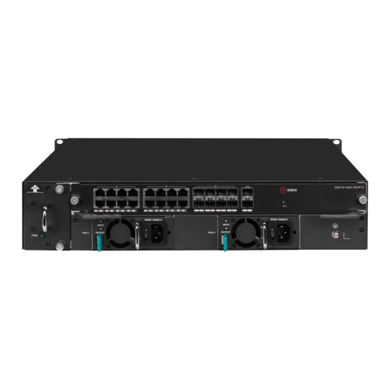
1. Router Introduction ROUTER INTRODUCTION QSR-3920-08 Appearance and Hardware QSR-3920 series router only has one product model: QSR-3920-08. QSR-3920-08 router has three kinds of slots: 3ESP, LX9, and MX9. The three slots are respectively inserted with RM3E-3ESP card, QSR-LX9-M-24GETS sub card, and MX9 interface card. -
Page 10: Introduction To 3Esp Card
The 3ESP card of QSR-3920 router supports hot-swap. Introduction to MIFC Card MIFC card is the management interface card of QSR-3920 router. The serial port, U disk interface, DC0 port and system status indicator of the device are all on the card. www.qtech.ru... -
Page 11: Introduction To M-3920 Interface Sub Card
The 24GETS interface card supports 24 10/100/1000M Ethernet ports, and its main function is to complete data forwarding. Figure 1-5 The appearance of M-3920 series card 1. Circuit board component area 2.Scew 3. Service port 4.Port indicator 5.Hot-swap indicator 6.Hot-swap button www.qtech.ru... -
Page 12: Introduction To Mx9 Series Card
QSR-3920-08 The QSR-3920-08 router provides two power module slots to realize 1 + 1 redundant backup of the power module, and the power module can also realize load balancing. The power module of QSR-3920 router supports hot-swap. www.qtech.ru... -
Page 13: Ac Power Module
7.Installation hole of cable anti-stripping strap Air Passage of QSR-3920 Series Router The air flow direction of QSR-3920 series router chassis is left in and right out, and the diagram is as follows: Figure 1-8 Air flow direction of QSR-3920 series router chassis ... -
Page 14: Qsr-M-3920-Fan Fan Module
Each QSR-3920-08 has one fan slot, which should be installed with one fan module QSR-M-3920- FAN to ensure the normal operation of the system. The schematic of the fan module is as follows. Figure 1-9 QSR-M-3920-FAN module 1. Handle 2. Fan indicator 3.Installation screw of fan card 4.Fan blade 5.Circuit board component area www.qtech.ru... -
Page 15: Installation Preparations
Check Router Running Environment QSR-3920 series routers must be used indoors. To ensure the normal running of the router, take the corresponding measures to meet the environment requirement of the router running: Air conditioning and ventilation system can ensure the normal running temperature and humidity conditions of the router. -
Page 16: Static Safety
Step 4: Ensure that the anti-static wrist is well-grounded. The using method of the anti- static wrist is shown in the following figure. Figure 2-1 Using method of anti-static wrist www.qtech.ru... -
Page 17: Laser Safety
Configurable termianl (a common PC or a laptop) Multimeter Open-Package and Inspection QSR-3920 series router adopts the carton packaging. The package comprises the carton, plastic bags, protection EPE and other packaging materials. The open-package steps are as follows: Step 1: View the carton label, and confirm the router model in the carton. -
Page 18: Install Router To Workbench
This section describes how to install the QSR-3920 series router to the 19-inch standard cabinet. Installation Preparations QSR-3920 series router is 2U high, so ensure that enough installation space is reserved for the router. Check the grounding and stability of the cabinet and ensure that there is no obstacle inside and around the cabinet affecting the router installation. - Page 19 This section is just for your reference. Goods in kind prevail. Install Floating Nut to Cabinet Before installing the chassis to the cabinet, first install the floating nut on the upright square hole bar on the both sides in the front of the cabinet. www.qtech.ru...
- Page 20 1.Installation locating plate of floating 2. Load bearing tray 3.Cabinet square hole column Step 2: Install the floating nuts on the marked positions. A floating nut must be installed on each installation hole on the hanging ear. Figure 3-3 Install the floating nut www.qtech.ru...
- Page 21 In some special installation environments, if it is necessary to install the device in reverse direction (the rear panel of the device is facing the front door of the cabinet), remove the hanging ears on both sides of the front www.qtech.ru...
-
Page 22: Ground The Router
Check and ensure that the router is installed correctly. Check and ensure that the router hanging ear and cabinet are secure and well. Check and ensure that enough space is reserved around the router for heat dissipation. Ground the Router www.qtech.ru... - Page 23 Figure 3-6 Connect the ground cable If there is no appropriate grounding point on the cabinet, we also can connect the grounding cable of the router to other grounding bar of the installation place. www.qtech.ru...
-
Page 24: Install Interface Sub Card Components (Optional)
Step 3: Push the buckle horizontally in the direction of the OPEN arrow to move the buckle about 2mm. At this time, the buckle will be loose and slightly spring up, and the buckle can be turned over manually. www.qtech.ru... - Page 25 Figure 3-11 Press down the buckle Figure 3-12 Push the buckle according to the direction of the LOCK arrow Step 6: Install QSR-MX9-M-4G-LTE interface daughter card to the router. Refer to "6.1 Replace interface daughter card" for the installation method of interface daughter card. www.qtech.ru...
-
Page 26: Install 4G Antenna
Remove the red plastic anti-dust cap on the antenna interface of the QSR-MX9- M-4G-LTE interface daughter card. Step 2: Insert 4G antenna into the antenna interface of QSR-MX9-M-4G-LTE interface sub card. Figure 3-14 Insert 4G antenna Step 3: Rotate the 4G antenna to the right and tighten it. www.qtech.ru... - Page 27 Some 4G interface sub cards use dual antennas, which are similar in installation, and will not be described here. For the dual-antenna 4G interface sub card, the left is the main antenna, and the right is the auxiliary antenna. The main antenna must be installed, and the auxiliary antenna www.qtech.ru...
-
Page 28: (Optional) Install Spd
(the PE is not detection indicator (red) connected or the live wire and naught wire are reversely connected). At this time, check the power supply circuit. 4.Power switch Turn on or turn off the power. www.qtech.ru... -
Page 29: (Optional) Install Port Lightning Protector
Step 2: Use a multimeter to test whether the lightning protector PE is well connected to the router ground terminal or the lightning protection ground copper bar in the equipment room. www.qtech.ru... -
Page 30: Install Power Supply
Install Power Supply Installation Preparations Take out the power module from the packing box and keep the accessories in the box. Confirm that the power module switch is in "off" state before installation. www.qtech.ru... -
Page 31: Install Power Module
Install the anti-stripping of the AC power cable to the installation hole of the power module panel. Figure 3-21 Install the anti-stripping Step 2: Insert the output plug of the power cable into the input jack of the power module. www.qtech.ru... -
Page 32: Check After Installation
Check and ensure that the PE is connected correctly. Check and ensure that the power cable is connected correctly. Check and ensure that the interface daughter card is installed and well-contacted. www.qtech.ru... -
Page 33: Power On And Run Router
(pin) serial interface socket of the PC (or laptop). The configuration cable is shown in Figure 4-1, and the connection diagram is shown in Figure 4-2. Figure 4-1 Console cable For details about the inner signal connection of the Console cables, refer to Appendix E1 Console Cable. www.qtech.ru... -
Page 34: Set Pc Hyperterminal Parameters
Figure 4-5. If it is the first time to set the Hyperterminal, the system displays the interface of Location Information, as shown in Figure 4-3. Fill in according to the red indication in the fiugre and click OK. www.qtech.ru... - Page 35 Display the following Telephone and Modem interface and click OK. Figure 4-4 The Telephone and Modem interface Step 3: Display the following Connection Description interface, and fill in the name in Name (N), such as test, and click OK. www.qtech.ru...
- Page 36 Figure 4-6 “Connect to” interface Step 5: Display the following COM1 Properties interface, set the baud rate as 9600, data bit as 8, parity check as none, stop bit as 1, and data flow control as none, and then click OK. www.qtech.ru...
- Page 37 4. Power on and Run Router Figure 4-7 “com* Properties” interface Step 6: Display the following test-HyperTerminal interface, and click Properties. Figure 4-8 “test-HyperTerminal” interface Step 7: Display the following “test properties” interface, click Setting, select VT100 in Terminal emulation, and click OK. www.qtech.ru...
-
Page 38: Power On And Start
Check before Power on Check the router before powering on: The interface cables, power cables, and PEs are connected correctly. Power supply voltage meets the power requirement of the device. For details, refer to Appendix C2 Requirements for Power Supply. www.qtech.ru... - Page 39 **************************************************************************** Operating System Software QSR-3920-08 (V1) system image file (flash0: /flash/rp39-7.3.2.75(R).pck), version 7.3.2.75(R)(integrity), Compiled on Sep 29 2017, 08:45:29 Copyright (C) 2014 QTECH LLC. All Rights Reserved. System ID : 08c6b32a453e Hardware Model : QSR-3920-08 (V1) with 2048 MBytes SDRAM, 8192 MBytes...
-
Page 40: Check After Power On
Insert one side of the Ethernet twisted pair to the Ethernet electrical interface of the router (RJ-45 port). Step 2: Insert the other side of the Ethernet twisted pair to the RJ-45 port of the device connected to the network. www.qtech.ru... -
Page 41: Access Network Via Fiber
Figure 4-11 Appearance of the LC fiber connector Install Optical Module The QSR-3920 series router supports the SFP optical module and the SFP optical module is installed as follows: When installing the SFP module, do not use the hands to touch the gold- finger of the SFP module directly. - Page 42 When installing the SFP module, do not use the hands to touch the gold- finger of the SFP module directly. The TX wire should be connected to the RX wire of the peer router; the RX wire should be connected to the TX wire of the peer router. www.qtech.ru...
- Page 43 Connect the other side of the fiber to the peer router. If the optical interface is not inserted with the SFP module, cover the dust cap of the optical interface. The dust cap of the optical interface is www.qtech.ru...
-
Page 44: Hardware Management
This section describes various hardware management functions of the QSR-3920 series router. With the function interfaces, the user can conveniently view the software and hardware version information of the QSR-3920 series router, as well as the work status information of the hardware modules. -
Page 45: View Power Module Status Information
Command: router#show system power Display as follows: System Power Information(Power 1 - ONLINE) ---------------------------------------------------------------- Type: QSR-M-3920-PWR-AC(V1)[0xf115] Status: Normal Serial No.: B554174272900106 Description: ---------------------------------------------------------------- STATISTICS: 1 IN, 0 OUT, 0 IERR, 0 OERR www.qtech.ru... - Page 46 2: Power 0 is inserted twice 1: Power 1 is inserted once IERR The error times of physically inserting the power supply, for example: 0: The error times of inserting Power0, Power1 is 0 The times of physically pulling out the power, for example: www.qtech.ru...
-
Page 47: View System Environment Temperature Information
Display as follows: System FAN Information(Fan 1 - ONLINE) ---------------------------------------------------------------- Status: Normal Serial No.: Description: Speed Rate: 64% ---------------------------------------------------------------- STATISTICS: 1 IN, 0 OUT, 0 IERR, 0 OERR System FAN Information(Fan 2 - ONLINE) ---------------------------------------------------------------- Status: Normal Serial No.: Description: www.qtech.ru... -
Page 48: View Swappable Optical Module Information
Fan-Speed Fan speed percentage View Swappable Optical Module Information You can use the show optical all command to view the work parameters of all optical modules used on QSR-3920 series router. Command: router#show optical all Display as follows: Name VendorName... - Page 49 (only for the optical module supporting the DDMI function) TxPower(dBm) The sending power of the optical module (only for the optical module supporting the DDMI function) RxPower(dBm) The receiving power of the optical module (only for the optical module supporting the DDMI function) www.qtech.ru...
-
Page 50: Troubleshooting
Parameters. Troubleshooting about Fan There is a fan status indicator on the panel of the QSR-3920 series router, which indicates the work status of the fan. The meaning of the indicator is shown in the following table. Table 5-1 Meanings of fan indicator on the panel of the fan module of QSR-3920... -
Page 51: Troubleshooting About Power
Off: indicates that the fan works abnormally. When the fan indicator on the panel of the QSR-3920 series router is off, it indicates that the system fan fails. View whether the fans rotate to confirm the faulty fan. Troubleshoot the faults according to the following steps. - Page 52 6. Simple introduction of the taken troubleshooting steps You can contact the customer service via the customer service hotline and you can also search for help via the website or email. Customer service: +7 (495) 797-33-11 * 555 Website: http://www.qtech.ru E-mail: support@qtech.ru www.qtech.ru...
-
Page 53: Router Maintenance
6. Router Maintenance ROUTER MAINTENANCE Change Module The QSR-3920 series router supports five types of board cards, 3ESP card, MIFC card, fan card, LX9 card and MX9 card. The MIFC card does not support hot swap. Change Power Module... -
Page 54: 3Esp Card
Figure 6-3 Pull out the 3ESP card 1 Step 2: Hold the puller on the 3ESP card with both hands and turn the puller outward to separate the 3ESP card from the chassis backplane. The figure below shows the diagram of pulling out the 3ESP card: www.qtech.ru... - Page 55 The following figure is the diagram of installing the 3ESP card: Figure 6-7 Install the 3ESP card 2 Step 6: Manually screw in the screws on both sides of the 3ESP card, and then tighten the screws with a screwdriver to fix the 3ESP card. www.qtech.ru...
-
Page 56: Change Mx9/M-3920 Interface Card
Figure 6-8 HOT SWAP button Step 2: Use a cross screwdriver to loosen the screws on the interface card to be replaced. Grasp the screws with both hands and pull them outwards to make the interface card separate from the frame panel. www.qtech.ru... -
Page 57: Change Fan Module
Before replacement, please prepare a new fan module in advance, and install a new fan module immediately after unplugging the fan module in the working state of the router to ensure the normal use of the router. www.qtech.ru... -
Page 58: Change Swappable Optical Module
Figure 6-12 Insert the fan module to the chassis Change Swappable Optical Module QSR-3920 series router supports the SFP module. The following describes how to change the SFP module. When installing or uninstalling the SFP module, do not use the hands to touch the gold-finger part of the SFP module directly. - Page 59 (you can feel that the shrapnel at the bottom and top of the SFP module locks the SFP slot), as shown in the following figure. Figure 6-15 Install the SFP module Step 5: Remove the dust cap of the SFP module, as shown in the following figure. www.qtech.ru...
-
Page 60: De-Dust The Router
Please first pull out the fiber and then install. De-dust the Router This section describes how to de-dust the QSR-3920 series router. The de-dusting mainly refers to the air inlet, outlet, swappable board card, and pigtail of the router. - Page 61 Step 3: The replaced and dedusted fan module will be used as the standby fan module. De-dust the Board Card To reduce the maintenance risks, de-dust the board card of the router in the period with small traffic volumes. www.qtech.ru...
- Page 62 De-dust Optical Interface and Pigtail Connector To ensure the long-term stable running of the router, de-dusting the optical interface and pigtail connector of the router is necessary. The de-dusting process is as follows: www.qtech.ru...
- Page 63 When the laser directly radiates the human eyes, it may cause permanent injury for the human eyes. It is forbidden to use any unapproved cleaning tools or materials to clean the optical interface or the pigtail connector. www.qtech.ru...
- Page 64 Appendix Table A-2 The weight of the frame/board card Model Weight (kg) QSR-3920-08 8.58 kg (including fan card, excluding power supply and inserted cards) QSR-M-3920-3ESP3 1.52kg QSR-M-3920-3ESP5 1.8kg QSR-M-3920-3ESP10 1.81kg QSR-LX9-M-24GETS 0.72kg QSR-M-3920-FAN 0.74kg QSR-M-3920-PWR-AC 1.08kg QSR-MX9-M-2SA(V2) 0.14kg QSR-MX9-M-1SA(V2) 0.12kg QSR-MX9-M-1CE1(V2) 0.12kg QSR-MX9-M-1E1(V2) 0.12kg www.qtech.ru...
- Page 65 0.13kg QSR-MX9-M-1GE(V1) 0.13kg QSR-MX9-M-1P-OC3(V2) 0.12kg QSR-MX9-M-4GEF(V1) 0.13kg QSR-MX9-M-4G-LTES(V1) 0.18kg QSR-MX9-M-4G-LTE(V1) 0.18kg QSR-MX9-M-4G-LTE-A(V1) 0.18kg Appendix Table A-3 The power consumption of the board card Model Power Consumption (W) QSR-M-3920-3ESP3 QSR-M-3920-3ESP5 QSR-M-3920-3ESP10 QSR-LX9-M-24GETS QSR-M-3920-FAN QSR-MX9-M-2SA(V2) QSR-MX9-M-1SA(V2) QSR-MX9-M-1CE1(V2) QSR-MX9-M-1E1(V2) QSR-MX9-M-4CE1(V2) QSR-MX9-M-4E1(V3) QSR-MX9-M-4GET(V1) www.qtech.ru...
- Page 66 The meanings of the QSR-M-3920-3ESP3 indicators are as follows: Appendix Table A-4 The meanings of the QSR-M-3920-3ESP3 indicators Name Indicator Color Status Description Green Flashing: device selected Off: device not selected Green Slowly flashing: indicates that the board is in normal operation state, 0.5Hz. www.qtech.ru...
- Page 67 Slowly flashing: indicates that the board is in normal operation state, 0.5Hz. Flashing quickly: indicates that the board is in IOS loading state, 5Hz. LINK/ACT 0~23 Green Off: interface not connected On: the interface connected, but there is no data received and sent www.qtech.ru...
- Page 68 Flashing quickly: indicates that the board is in IOS loading state, 5Hz. LINK/ACT 0~23 Green Off: interface not connected On: the interface connected, but there is no data received and sent Flashing: the interface connected, and there is data received and sent www.qtech.ru...
- Page 69 Flashing: Link interface has data sent and received There are two types of port indicators: ▲ and▼, ▼ indicates the status of the lower 0, 2, 4…. and other even port, ▲ indicates the status of the upper 1,3,5 … and other odd ports. www.qtech.ru...
- Page 70 One RJ45 interface, asyn serial port, default baud rate: 9600bps; One micro USB console interface; Multiplexing mode, auto switching, RJ45 interface preferred. Micro USB Configuration port, one Micro USB interface One U-disk slot Reset key (press for 3s, and the device restarts) www.qtech.ru...
- Page 71 CONSOLE port Yellow Off: The interface has not data sent indicator Flashing: The interface has data sent Green Off: The interface has not data received Flashing: interface data received DC0 port indicator Yellow On: The interface rate is 1000M www.qtech.ru...
- Page 72 The diagram of the QSR-M-3920-FAN panel: Appendix Figure A-6 QSR-M-3920-FAN panel QSR-M-3920-FAN is used for QSR-3920, one is required. The meanings of the QSR-M-3920-FAN indicators are as follows: Appendix Table A-11 The meanings of the QSR-M-3920-FAN indicators Name Indicator Color Status Description www.qtech.ru...
- Page 73 A6 QSR-M-3920-PWR-AC Power Module QSR-3920 series routers support two modular power slots and two power modules 1 + 1 redundancy backup. For reliability, it is recommended that customers configure two power supplies of the same model. The diagram of QSR-M-3920-PWR-AC power module panel is as follows:...
- Page 74 B1 10GBase-SR/LR/ER-SFP+ Optical Interface Attributes Appendix Table B-1 10GBase-SR/LR/ER-SFP+ Attribute Description Interface Standard IEEE 802.3ae Interface type SFP+ Work modes 10GBASE-ER 10GBASE-LR 10GBASE-SR 10GBASE-EW 10GBASE-LW 10GBASE-SW 10.3125Gbps(LAN mode) Connector SFP+ Support SFP+ module type Support 10GBASE-SR Support 10GBASE-LR Support 10GBASE-ER www.qtech.ru...
- Page 75 B3 1000Base-X-SFP Optical Interface Attributes Appendix Table B-3 1000Base-X-SFP Attribute Description Interface standard IEEE 802.3ab Interface type Work mode 1000Mbps full-duplex Connector Supported SFP module type Gigabit SFP optical module Gigabit SFP BiDi module Connection cable Single mode fiber or multimode fiber www.qtech.ru...
- Page 76 Connect the local terminal (such as PC) and run the terminal emulation program on the terminal. B6 Micro USB Interface Attributes Appendix Table B-6 Micro USB interface attributes Attribute Description Interface standard USB2.0 Interface type Micro usb Work mode 12Mbps Cables Standard USB AM-to-MICRO USB cable: www.qtech.ru...
- Page 77 To ensure that the router can work normally, it is recommended to maintain certain humidity in the equipment room. The work humidity requirement is shown in the following table. Appendix Table C-2 Work humidity requirements Description Humidity Work condition 5%–85%, no-condensing Storage Condition 0%–95%, no-condensing www.qtech.ru...
- Page 78 If there is no visible dust on the desk within three days, it meets the cleanliness requirement. Apart from dust, the router equipment room has the strict requirements for salts, acids, and sulfides contained in the air, because these harmful gases speed up the eroding of metals and the aging of some components. www.qtech.ru...
- Page 79 The well grounding system is the basis for the router to run stably and reliably, and the important guarantee for lightning protection, anti-interference, and anti-static of the router. The user should provide the well grounding system for the router. The resistance between the router chassis and the ground should be smaller than 1 ohm. www.qtech.ru...
- Page 80 Code for fire protection design of tall buildings GB50045- 95. The low-voltage distribution is done according to Specifications for the design of low-voltage electric power distribution systems GB50045-95. C2.2 Suggestions on fundamental AC power supply Suggestions on fundamental AC power supply include: www.qtech.ru...
- Page 81 The capacity thereof shall be checked to be not less than 1.5-2 times the total capacity of the AC incessant consumers. www.qtech.ru...
- Page 82 The router grounding specification is as shown in the following table. Appendix Table D-2 Router grounding specification Description The router protection ground (PGND) shall be short-circuited nearby to the protection grounding cooper bar provided by the user, with the short- www.qtech.ru...
- Page 83 The working ground and protection ground of DC power shall share a same group of ground body with the protection ground of communication equipment, and when the communication power and communication equipment are in the same room, they shall share the protection ground bar in the same room. www.qtech.ru...
- Page 84 Grounding cable cannot be led aerially, but should be buried in the earth or routed indoor. On the protection ground wire, prohibit installing the connectors; prohibit installing the switch or fuse. The protection ground wire should adopt the yellow and green plastic insulated copper-core lead. www.qtech.ru...
- Page 85 If you cannot lay and bury all outdoor cables, the aerial cables should be dressed with the metal pipes 15m before entering the indoor. The two sides of the metal pipe are grounded and we should install the signal arrester at the corresponding interface of the router after the cable enters the indoor. www.qtech.ru...
- Page 86 Before connection, we should use the dust-free paper to soak the anhydrous alcohol and wipe the insert core of the fiber connector. You can wipe in one direction only and you also need to wipe the surface of the peer fiber connector. www.qtech.ru...
- Page 87 It is recommended that the user performs the ground protection at the user end of the fiber optic cable. D2.3 Equipotential Connection Method www.qtech.ru...
- Page 88 After connection, use the multimeter to measure whether each equipotential connection point well contacts and the impedance is low enough. Appendix figure D-1 Diagram of router equipotential connection 1. Router ground terminal 2. Router equipotential connection line 3. Ground protection cable 4. Ground bar www.qtech.ru...
- Page 89 The connection relationship of the internal signal of the console cable is shown in the following table. Appendix Table E-1 Connection relationship of the console cable RJ-45 Signal Direction DB-9 → → → ―― ―― ―― ← ← ← ―― ―― ―― ―― www.qtech.ru...
- Page 90 E2 GE Ethernet Interface Cable The GE Ethernet interface cable of the QSR-3920 series router is an eight-core unshielded twisted cable. Port 1 and port 2, port 3 and port 6, port 4 and port 5, and port 7 and port 8 consist of four pairs of bidirectional receiving and transmitting difference cable pairs.
- Page 91 For the use conditions of the product in the environmental protection use period, refer to the requirements for the use environment in the product manuals. In the statement, list all components that may be configured in QTECH products. For the actual components contained in each product, please prevail in kind.
Need help?
Do you have a question about the QSR-3920 Series and is the answer not in the manual?
Questions and answers