Amerec AI 18 Installation Instructions Manual
Commercial steam generator
with coolflush auto drain option
boilers for large steam rooms 208 and 240v 1 & 3 phase, and 480v 3 phase
Hide thumbs
Also See for AI 18:
- Installation instructions manual (12 pages) ,
- Installation instructions manual (26 pages)
Advertisement
Quick Links
COMMERCIAL STEAM GENERATOR
WITH COOLFLUSH™ AUTO DRAIN OPTION
BOILERS FOR LARGE STEAM ROOMS
INSTALLATION INSTRUCTIONS
MODELS AI 12, AI 18 AI 24, AI 30, AI 36, AI 42 & AI 48
208 and 240V 1 & 3 phase, and 480V 3 phase
WITH COOLFLUSH™ AUTO DRAIN OPTION
4211-163 09-17-13
Technical Support: 1-800-363-0251
support@amerec.com
1 of 26
Advertisement

Related Manuals for Amerec AI 18


Summary of Contents for Amerec AI 18
- Page 1 WITH COOLFLUSH™ AUTO DRAIN OPTION BOILERS FOR LARGE STEAM ROOMS INSTALLATION INSTRUCTIONS MODELS AI 12, AI 18 AI 24, AI 30, AI 36, AI 42 & AI 48 208 and 240V 1 & 3 phase, and 480V 3 phase WITH COOLFLUSH™ AUTO DRAIN OPTION...
- Page 2 WATER LEVEL CONTROL BLOWDOWN/ CoolFlush™ Auto Drain option BLOWDOWN/MANUAL DRAIN APPENDIX 1: RUN CLOCK AND AUTOBLOWDOWN CLOCK APPENDIX 2: PRESSURE CONTROL ASSEMBLY APPENDIX 3: LOW WATER CUTOFF INSTRUCTIONS SAVE THIS MANUAL 4211-163 09-17-13 Technical Support: 1-800-363-0251 support@amerec.com 2 of 26...
- Page 3 You may be required to present this form to a state, provincial or other inspection agency. Secure this document in a safe location. Thank you for purchasing your new AMEREC steam generator. If we can be of any assistance do not hesitate to call our Technical Support at 1-800-363-0251.
-
Page 4: Important Safety Instructions
Fetal damage in pregnant women: e. Physical inability to exit the steambath: and Unconsciousness. WARNING The use of alcohol, drugs or medication can greatly increase the risk of hyperthermia SAVE THESE INSTRUCTIONS 4211-163 09-17-13 Technical Support: 1-800-363-0251 support@amerec.com 4 of 26... - Page 5 There are no user serviceable parts in this equipment. Electrical grounding is required on all AMEREC steambath generators. The generator is designed for hookup with copper wire only, 75°C or better.
-
Page 6: General Information
“blowing down” the generator when it is not heating. The “blow down” process involves removing a portion of the tank water with high solid concentration and replacing it with makeup water. 4211-163 09-17-13 Technical Support: 1-800-363-0251 support@amerec.com 6 of 26... - Page 7 To reduce corrosion and element damage risks, always flush feedwater lines thoroughly to eliminate flux residue and avoid sodium based water softeners. The ASX-200 filter system available from Amerec provides very good protection in most installations and should be connected to a cold water supply. Feedwater temperature must be no hotter than 100°F if the ASX-200 is installed!
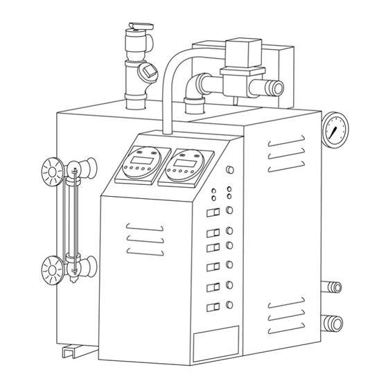
- Page 8 BEFORE REMOVING THIS COVER NO USER SERVICEABLE PARTS WITHIN SERVICE ONLY BY AUTHORIZED PERSONNEL FOR ASSISTANCE CALL 1-800-331-0349 ALL MODELS ALL MODELS Shown with optional boiler mounted thermostat. All dimensions in inches. 4211-163 09-17-13 Technical Support: 1-800-363-0251 support@amerec.com 8 of 26...
-
Page 9: Installation
A check valve is installed in the boiler’s feedwater line. An additional customer supplied back-flow prevention device may be required in your area. Check local codes. To prevent water level sensing errors, backflow 4211-163 09-17-13 Technical Support: 1-800-363-0251 support@amerec.com 9 of 26... - Page 10 20 feet long, best results can be obtained by insulating the steam pipe. Any insulation must be suitable for temperatures of at least 250°F. 6” min. 12” min. 12” min. Seal rear 12” min. Of insulator With silicone 15 to 18” 4211-163 09-17-13 Technical Support: 1-800-363-0251 support@amerec.com 10 of 26...
- Page 11 NOTE: A GFCI device is not required by UL. A GFCI may be installed if required by local codes or the owner. A GFI device will tend to nuisance trip due to heater element aging. 4211-163 09-17-13 Technical Support: 1-800-363-0251 support@amerec.com 11 of 26...
- Page 12 Run a bead of 100% silicone caulk around the underside of the sensor head then carefully feed the cable and sensor through the hole and attach the sensor in place. 4211-163 09-17-13 Technical Support: 1-800-363-0251 support@amerec.com 12 of 26...
- Page 13 1/2" holes in the wall studs or ceiling joists to the generator and the switch box installed at the desired control mounting location. The switch location jumpers must be correctly set for proper operation. 4211-163 09-17-13 Technical Support: 1-800-363-0251 support@amerec.com 13 of 26...
- Page 14 3 to 3. Use a small screwdriver to carefully press the terminal BLACK WIRE block’s orange tabs down to insert or remove the wire ends. When only one steam outlet valve is available, always connect to ROOM 1. 4211-163 09-17-13 Technical Support: 1-800-363-0251 support@amerec.com 14 of 26...
- Page 15 WIRING: AI 12, AI 18 and AI 24 ALL WIRING MUST BE INSTALLED BY A LICENSED ELECTRICAL CONTRACTOR IN ACCORDANCE WITH ALL APPLICABLE LOCAL AND NATIONAL CODES. ELECTRICAL GROUND REQUIRED ON ALL STEAMERS. ELECTRIC SHOCK HAZARD – HIGH VOLTAGE EXISTS WITHIN THIS EQUIPMENT.
- Page 16 LEDS 3241-02x POWER & LEVEL CONTROL PRINTED CIRCUIT BOARD LEVEL PROBES AUTODRAIN SOLENOID WATER OFF (OPTION) HEAT OKAY WATER ON HEAT OFF MANUAL OPEN DRAIN VALVE OPEN LIGHT AUTODRAIN CLOCK (OPTION) 4211-163 09-17-13 Technical Support: 1-800-363-0251 support@amerec.com 16 of 26...
- Page 17 60 switch to start the steam bath and begin heating the room. The status LEDs on the thermostat(s), switches and boiler will light and remain on continuously when the steam bath is on and operating normally. 4211-163 09-17-13 Technical Support: 1-800-363-0251 support@amerec.com 17 of 26...
- Page 18 60 switch option is not installed. When the bath is turned off, the generator’s steam valve will remain closed and the thermostat LED, the Refresh™ switch’s LED and the corresponding ROOM 4211-163 09-17-13 Technical Support: 1-800-363-0251 support@amerec.com 18 of 26...
- Page 19 MAX. WORKING PRESSURE: STEAM, 15 psi 2 0 8 3 6 8 MODEL MAX. kW 50/60 Hz PHASE AMPS MAX. CAPACITY LISTED BOILER lb.s PER HOUR ASME MARKINGS LOCATED ON SHELL 4211-163 09-17-13 Technical Support: 1-800-363-0251 support@amerec.com 19 of 26...
- Page 20 For reliable operation, your site may require water treatment. 4211-163 09-17-13 Technical Support: 1-800-363-0251 support@amerec.com 20 of 26...
- Page 21 5 seconds to indicate that the drain is not functioning and servicing is necessary. The drain cycle will not operate again until power has been reset. 4211-163 09-17-13 Technical Support: 1-800-363-0251 support@amerec.com 21 of 26...
- Page 22 Reset all switches and the thermostat to their normal positions when done. If the water drains slowly or sporadically, it may be necessary to remove the element assembly and clean the tank by hand. If this condition is seen, stop using the generator and call Amerec Technical Support for assistance.
- Page 23 DRAIN CLOCK (Rear View) RUN CLOCK (Rear View) REAR VIEW The drain valve’s wires are connected to the power wire from the DRAIN CLOCK and a Neutral lead in the generator’s contactor compartment. 4211-163 09-17-13 Technical Support: 1-800-363-0251 support@amerec.com 23 of 26...
-
Page 24: Pressure Control Assembly
A fitting is supplied to allow connecting a second pressure gauge to easily replace the supplied gauge or to connect a second gauge for inspection. A ball valve is supplied assist with gauge changes; the valve should be left open during normal operation. 4211-163 09-17-13 Technical Support: 1-800-363-0251 support@amerec.com 24 of 26... - Page 25 Two more wires are used between the control and the LWCO level probe. Refer to the wiring diagrams below when installing your LWCO. The following wiring steps refer to the Taco LFM120R1 LWCO available through Amerec. See the manufacturer’s instructions provided with the LWCO for further details. BOILER...
- Page 26 5. Test the installation following the manufacturer’s instructions. Test and Reset switches and status lights are located on the top of the LWCO. Refer to the manufacturer’s instructions for further details. For service or assistance contact Amerec Technical Support, 7:00 am to 5:00 pm Pacific Time 1-800-363-0251.
Need help?
Do you have a question about the AI 18 and is the answer not in the manual?
Questions and answers