Advertisement
R30
OR
K60/KT60
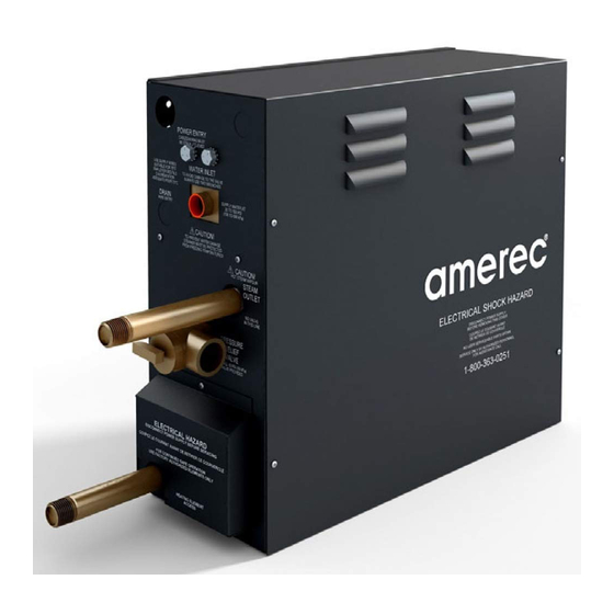
AMEREC AK4.5, AK7.5, AK11 and AK14
STEAMBATH GENERATORS
nstructions for 208V and 240V 1/3 Phase Models.
I
(Use 240V models for 400-415V~N3 installations)
FOR USE WITH R30, K60 AND KT60 CONTROLS
SAVE THESE INSTRUCTIONS
READ ALL INSTRUCTIONS CAREFULLY BEFORE INSTALLATION.
POST SAFETY "WARNING" LABEL OUTSIDE STEAMBATH. LABEL
SHOULD BE POSTED ON OR ADJACENT TO DOOR TO STEAM
ROOM IN COMMERCIAL INSTALLATIONS.
SECTION 1: GENERAL INFORMATION
Amerec steam generators are tested by Intertek-ETL Laboratory. The
steam generators come assembled and ready for installation. Check that
the size and rating of the generator is suitable for your application:, refer to
the AK Steam Room Sizing and Rough-in Guide (Amerec doc. 4211-36).
The AK steamers may be connected as a ganged system where one
steamer controls one or two other steamers. Bath controls connect to the primary steamer and the primary steamer
connects to the second steamer (and third steamer, if installed). This provides more power for large rooms and light
commercial use. See appendix to this document for details.
We recommend choosing steamers which are closely matched in power. The highest kW steamer should be the
primary unit. Each steamer should have its own automatic drain.
For commercial use, we recommend checking with your local inspectors to confirm the AK system is acceptable for
your use. Many jurisdictions will require an ASME boiler for commercial use: AK steamers are not boilers.
Note: The AK steamer may be configured for single or three phase power during installation
IMPORTANT
An exhaust fan installed outside the steam room is strongly recommended
to remove excess steam from the bathroom or shower area.
4211-1551
06/18/18
AK INSTALLATION AND SERVICE INSTRUCTIONS
AK STEAM GENERATOR
Technical Support: 1-425-951-1120
Electrical grounding is required on all
AMEREC Steam bath Generators.
All electrical supplies should be
disconnected when servicing generator.
All wiring must be installed by a licensed
electrical contractor in accordance with
local and national codes.
All plumbing must be installed by a
licensed plumber in accordance with all
applicable local and national codes.
AK series generators are
AK series generators are not for
space heating purposes.
Be certain that steam bath enclosures
are properly sealed to avoid water
damage from escaping steam. It is
recommended that 100% silicone caulk
be used to seal all pipes and fittings.
Steam must be prevented from escaping
Never shut off the water to a
steam generator that is in use.
Electric Shock Hazard - High voltage
exists within this equipment. There
are no user serviceable parts in this
1-800-363-0251
support@amerec.com
CAUTION
for indoor use only.
into the wall cavity.
equipment.
Page 1 of 20
Advertisement
Table of Contents

Related Manuals for Amerec AK14


Summary of Contents for Amerec AK14
- Page 1 AK Steam Room Sizing and Rough-in Guide (Amerec doc. 4211-36). The AK steamers may be connected as a ganged system where one steamer controls one or two other steamers. Bath controls connect to the primary steamer and the primary steamer connects to the second steamer (and third steamer, if installed).
-
Page 2: Table Of Contents
Water Quality Requirements Plumbing Instructions 9-12 Wiring Instructions Electrical Information Chart Bath Control Installation 14-16 Control Options Initial Start Contact Information Wiring Diagrams 19-20 AK System Installation Instructions Appendix 4211-1551 06/18/18 Technical Support: 1-425-951-1120 1-800-363-0251 support@amerec.com Page 2 of 20... -
Page 3: Important Safety Instruction
There are no user serviceable parts in this equipment. Electrical grounding is required on all AMEREC steambath generators. The generator is designed for hookup with copper wire only, 75°C or better. - Page 4 être effectuée par du personnel autorisé qualifié conformément aux codes locaux et nationaux. Il n'y a pas de pièce réparable par l'utilisateur à cet équipement. Mise à la terre électrique est requis sur tous les générateurs bain de vapeur AMEREC. Le générateur est conçu pour connecter un fil de cuivre uniquement, 75 °C ou mieux.
- Page 5 AK INSTALLATION AND SERVICE INSTRUCTIONS POST "WARNING LABEL OUTSIDE STEAMBATH FOR SAFETY WARNINGS Étiquette d'avertissement "Extérieur poste baiin de vapeur pour les avertissements relatifs à la sécurité 4211-1551 06/18/18 Technical Support: 1-425-951-1120 1-800-363-0251 support@amerec.com Page 5 of 20...
- Page 6 Dommages au foetus chez les femmes enceintes : Incapacité physique pour quitter le bain de vapeur : et L'inconscience. Avertissement - La consommation d'alcool, de drogues ou de médicaments peut augmenter considérablement le risque d'une hyperthermie 4211-1551 06/18/18 Technical Support: 1-425-951-1120 1-800-363-0251 support@amerec.com Page 6 of 20...
-
Page 7: Mounting The Generator
[335,3 mm] Leave 13” [330 mm] Service Clearance The AMEREC steam generator can be hung on a wall or sit on its base. The best mounting location will satisfy all or most of the following: WARNING: The generator will not operate properly, unless it is mounted level with the arrows pointed up 1. -
Page 8: Water Quality Requirements
10 – 30 ppm - (0.5 - 1.75 gpg) T-Alkalinity 150 – 700 ppm - (8.75 - 40.8 gpg) Silica Range 15 – 25 ppm - (1.28 - 1.45 gpg) PH (strength of alkalinity) 10.5 -- 11.5 4211-1551 06/18/18 Technical Support: 1-425-951-1120 1-800-363-0251 support@amerec.com Page 8 of 20... -
Page 9: Plumbing Instructions
The steam line outlet should be at least 6” (150 mm) from other steam heads to either side and 12” (305 mm) from walls or other surfaces to either side. See Diagrams 4, 5 and 6. 4211-1551 06/18/18 Technical Support: 1-425-951-1120 1-800-363-0251 support@amerec.com Page 9 of 20... - Page 10 If a hand tight fit 1/2 NPT does not align with the opening pointing down, use Teflon tape on the steam line threads to adjust the fit. 4211-1551 06/18/18 Technical Support: 1-425-951-1120 1-800-363-0251 support@amerec.com Page 10 of 20...
- Page 11 25 minutes VALVE after a steam bath stops. This cleans the tank to reduce problems caused by poor water quality and ensures every steam bath starts with clean, fresh water. Contact Amerec Technical Support Support@Amerec.com or 1-425-951-1120 for more information.
-
Page 12: Wiring Instructions
AK11 & AK14 208V single phase and AK14 240V single phase require this method See page 20 for Mains Wiring Details. Note: jumpers shown are supplied with the steamer. 4211-1551 06/18/18 Technical Support: 1-425-951-1120 1-800-363-0251 support@amerec.com Page 12 of 20... -
Page 13: Electrical Information Chart
Room Size cu ft Room Size cu m Model Notes: * Use only copper wire rated 600V~ and AK4.5 75°C minimum * All models require Earth ground * All line voltage must be more than 195V~ AK7.5 while the steamer is heating... -
Page 14: Bath Control Installation
Tile up to the hole in mounting plate as indicated in Diagram 10. DIAGRAM 10 TEMPERATURE SENSOR USE WITH K60 ONLY 2” (50 mm) HOLE KT60 4211-1551 06/18/18 Technical Support: 1-425-951-1120 1-800-363-0251 support@amerec.com Page 14 of 20... - Page 15 Use a 1-1/2” (36 mm) hole saw to drill a hole in the finished steam room wall where the control is to be mounted (the control cable should already be roughed-in to this location). See Diagram 13 4211-1551 06/18/18 Technical Support: 1-425-951-1120 1-800-363-0251 support@amerec.com Page 15 of 20...
- Page 16 Run a bead of 100% silicone caulk around the perimeter on the back of the control housing. Insert the control into the wall cavity. See Diagram 13. Connect the R30i control's cable wires to the steamer's circuit board terminal block. See Diagram 13. 4211-1551 06/18/18 Technical Support: 1-425-951-1120 1-800-363-0251 support@amerec.com Page 16 of 20...
-
Page 17: Control Options
For installations with K60 or KT60 controls, the temperature display can be set to Fahrenheit (°F) or Celsius (°C). Set the circuit board jumper as shown above. The jumper is located at the right edge of the board just above the AK IN jack. 4211-1551 06/18/18 Technical Support: 1-425-951-1120 1-800-363-0251 support@amerec.com Page 17 of 20... -
Page 18: Initial Start
KT60 Control is used (depending on its TIME setting). When the time runs out the steam will stop and there should not be any water flow. The control should not be lit. For assistance, contact P.O. Box 2258, Woodinville, WA 98072 Phone 1-800-363-0251 1-425-951-1120 1-425-951-1130 eMail Support@amerec.com 4211-1551 06/18/18 Technical Support: 1-425-951-1120 1-800-363-0251 support@amerec.com Page 18 of 20... -
Page 19: Wiring Diagrams
AK INSTALLATION AND SERVICE INSTRUCTIONS (OPTIONAL) SERVICE PINS (OPTIONAL) CONNECT AK TEMP SENSOR (WITH K60 ONLY) R30i JUMP FOR ON/OFF R30K FROM K60AND/OR KT60 CONTROLS (MOMENTARY) © AMEREC DRAIN COMMON 60 min/24 HR 60m/24HR NORM/EX T NORM / EXT-TIMER °F/°C °F/°C INPUT FROM... - Page 20 See Note CIRCUIT 2 CIRCUIT 1 208V L1 208V L2 208V L1 208V L2 208V Models 208V 3 phz AK4.5 to AK14 North America AK STEAMER FIELD WIRING AMPS 1 Phase WATTS AMPS 3 Phase (V~ 3N) Model 208V 240V...
- Page 21 SLIPPING AND FALL INJURY Use care when entering or exiting the steam room, floor may be slippery. The Amerec Steam Generator can be hung on a wall or set on it’s base. The best mounting location will 05-21-07 NOTE: For additional safety instructions, see owner's manual.
- Page 22 See diagram 15. 11. Refer to the mounting instructions in Amerec AK installation instructions document 4211-1551 for details regarding mounting individual steamers. Refer to the following diagrams for some suggested systems (and some not allowable steam pipings).
- Page 23 • Do not use a saddle valve or saddle fi tting for the water shut-off valve. • Flush water supply line before fi nal hookup. Page 3 4211-1551 06/18/18 Technical support: 1-425-951-1120 1-800-363-0251 support@amerec.com...
- Page 24 The valve must be within 6” (150 mm) of the steam tank. Run a 3/4” copper pipe from the valve to an appropriate drain. Do not connect the valve’s outlet to the generator’s drain line! Do not connect the valve’s outlet to the steam line! Page 4 4211-1551 06/18/18 Technical support: 1-425-951-1120 1-800-363-0251 support@amerec.com...
- Page 25 W-D COM S30B S60 A S60 B 60m/24HR NORM/EXT 100mA TIME DELAY F/ C 1A NON-TIME DELAY 12 3 12 3 AK I N AK I N SECONDARY STEAMER SECONDARY STEAMER Page 5 4211-1551 06/18/18 Technical support: 1-425-951-1120 1-800-363-0251 support@amerec.com...
- Page 26 fl ow. THE SYSTEM IS NOW READY FOR OPERATION. Technical Support PO Box 2258 Woodinville, WA 98072 Phone 1-800-363-0251 1-425-951-1120 FAX 425-951-1130 email: support@amerec.com Page 6 4211-1551 06/18/18 Technical support: 1-425-951-1120 1-800-363-0251 support@amerec.com...
Need help?
Do you have a question about the AK14 and is the answer not in the manual?
Questions and answers