Advertisement
Quick Links
Installation Instructions
Model PSR-1
Remote Power Supply
INTRODUCTION
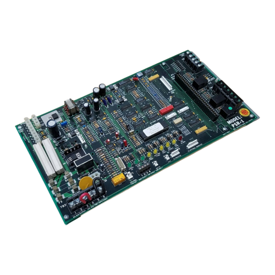
The Model PSR-1 from Siemens Industry, Inc.,
(See Figure 1) is a microprocessor controlled
remote power supply and battery charger used
with the MXL System. It operates with an
MPS-6 or MPS-12 to provide 6 or 12 amps,
respectively, of power for various MXL mod-
ules.
In addition, the PSR-1 acts as an interface
between remote option modules and the MXL
when used with a NET-4 plug-in communica-
tion module (See Instructions P/N 315-090909)
or NET-7 plug-in communication module (See
Instructions P/N 315-091914).
Siemens Industry, Inc.
Building Technologies Division
Florham Park, NJ
P/N 315-090911-23
Figure 1
PSR-1 Remote Power Supply
The PSR-1 can also be used to power an
MOI/MOD annunciator driver set. In addition, the
PSR-1 can be used as an auxiliary power supply
in a standalone mode without an MXL.
The PSR-1 has LED status indicators for:
POWER ON, 5V AUX ON, 24V ON, BAT TRBL,
TB3 TRBL (Class A power limited output for the
CZM-1 and PS-5), GND FAULT, XMIT, ANY
TRBL, and ANY ALARM. The PSR-1 has two
relays used for common alarm and common
trouble. These relays also can be programmed
for local alarm and local trouble using CSG-M.
For additional information on the MXL/MLV
System, refer to the MXl/MXLV Manual,
P/N 315-092036.
Siemens Building Technologies, Ltd.
Fire Safety & Security Products
2 Kenview Boulevard
Brampton, Ontario
L6T 5E4 Canada
Advertisement

Related Manuals for Siemens PSR-1


Summary of Contents for Siemens PSR-1
-
Page 1: Installation Instructions
Remote Power Supply Figure 1 PSR-1 Remote Power Supply INTRODUCTION The PSR-1 can also be used to power an MOI/MOD annunciator driver set. In addition, the The Model PSR-1 from Siemens Industry, Inc., PSR-1 can be used as an auxiliary power supply (See Figure 1) is a microprocessor controlled in a standalone mode without an MXL. -
Page 2: Electrical Connections
Primary Power For FM Appoved Deluge/PreAction Primary power for the PSR-1 is provided by the systems multiply the total system current by MPS-6 or MPS-12. Both of these mount in the 90 and record it at that Total AH location. - Page 3 NOTES: 1. Use this column for battery size calculations. 2. Power is supplied by a separate UPS. 3. EOL currents included. 4. The following modules draw no 24 i t c VDC current and do not need to be included in the battery calculations: LLM-1 OMM-1...
- Page 4 2. Use this column to calculate total current from 5 VDC supply to make sure it is not overloaded. i t c 3. PSR-1 supplies 5V at 800mA, 24V at 6A t i u (MPS-6), 24V at 12A (MPS-12). 4. The following modules...
-
Page 5: Electrical Ratings
To Disable the Tamper Switch There is only one allowable battery switch setting The PSR-1 does not support the use of security as shown in the table below. Be sure to set the points from initiating circuits in its enclosure. To... - Page 7 3, and 4. For a NET-7 network connected to an the upper left portion of the mounting plate. MMB-3, refer to Figure 5. When the PSR-1 is used as a standalone power supply, neither NET-4 nor 2. Secure it in place using the hardware provided.
- Page 8 MXL. Likewise, if any REFER TO WIRING SPECIFICATION FOR MXL, MXL-IQ AND MXLV SYSTEMS, P/N 315-092772 REVISION 6 OR local module, including the PSR-1, loses communi- HIGHER, FOR FURTHER INFORMATION. cation with the MXL, the trouble relay transfers.
-
Page 9: Wiring Diagram
MOI-7. In this configura- AND MXLV SYSTEMS, P/N 315-092772 REVISION 6 OR HIGHER, FOR FURTHER INFORMATION. tion the MOI-7 and the PSR-1 must be in the POSITIVE AND NEGATIVE GROUND FAULT DETECTED AT <30K OHMS FOR TB3, 1-6 same enclosure. - Page 10 TB3 for the MOM-4 card cage. This output is rated at 6 amps (MPS-6) or 12 amps When a PSR-1 is used with an MKB-2, use a MOM- (MPS-12) 18-31 VDC. This capacity must be 4 for the NET-7. Connect as shown in Figure 14.
- Page 11 REFER TO WIRING SPECIFICATION FOR MXL, MXL-IQ AND MXLV SYSTEMS, P/N 315-092772 REVISION 6 OR HIGHER, FOR ADDITIONAL WIRING INFORMATION. Figure 14 Connecting a NET-7 in a MOM-4 POSITIVE AND NEGATIVE GROUND FAULT DETECTED AT <30K OHMS FOR TB3, 1-6 REFER TO WIRING SPECIFICATION FOR MXL, MXL-IQ AND MXLV SYSTEMS, P/N 315-092772 REVISION 6 OR HIGHER, FOR ADDITIONAL WIRING INFORMATION.
- Page 12 P/N 315-090911-23...
Need help?
Do you have a question about the PSR-1 and is the answer not in the manual?
Questions and answers