Viessmann Vitosol 222-T Installation Instructions Manual
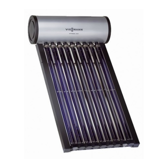
Type ts vacuum tube collector based on the heat pipe principle and dhw cylinder
Hide thumbs
Also See for Vitosol 222-T:

Related Manuals for Viessmann Vitosol 222-T


Summary of Contents for Viessmann Vitosol 222-T
- Page 1 VIESMANN Installation instructions for contractors Vitosol 222-T Type TS Vacuum tube collector based on the heat pipe principle and DHW cylinder VITOSOL 222-T Dispose after installation. 5719 917 UAE 1/2011...
- Page 2 Safety instructions Please follow these safety instructions closely to prevent accidents and mate- rial losses. Safety instructions explained Working on the system Please note ■ Isolate the system from the power sup- This symbol warns against the ply and check that it is no longer 'live', risk of material losses and envi- e.g.
-
Page 3: Table Of Contents
Index Installation sequence Preparing the DHW cylinder................. ■ Without immersion heater................. ■ In conjunction with the immersion heater (on site)..........■ Safety valve (T&P valve) (required accessory)..........Elevated installation..................... ■ Ballast and max. load on the substructure............Installation on pitched roofs.................. 12 Connecting the equipotential bonding.............. -
Page 4: Preparing The Dhw Cylinder
Preparing the DHW cylinder Without immersion heater Accessories, comprising the follow- ■ Cover ing components: ■ Flange gasket ■ Flange cover with magnesium anode ■ Thermal insulation In conjunction with the immersion heater (on site) Accessories, comprising the follow- ■ Cover with opening for feeding in the ing components: power cable ■... - Page 5 Preparing the DHW cylinder (cont.) A DHW connection C Cold water connection B Safety valve (see page 4)
- Page 6 Preparing the DHW cylinder (cont.) Note After step 7, pull out the power cable briefly to ensure the seal. Tighten the screws on the flange cover with a maximum torque of 25 Nm.
-
Page 7: Elevated Installation
Elevated installation Information before installation If an immersion heater (on site) is to be installed, maintain a minimum clearance of 450 mm between the DHW cylinder cover and any walls. - Page 8 Elevated installation (cont.) A Foot support A B Foot support B...
-
Page 9: Ballast And Max. Load On The Substructure
Elevated installation (cont.) Ballast and max. load on the substructure Calculations to DIN 1055-4 03/2005 and The details in the following tables refer to DIN 1055-4 03/2006. heights of up to 800 m above sea level. Securing against slippage Installation height <10 10–20 above ground in m... - Page 10 Elevated installation (cont.) 4x 10.
- Page 11 Elevated installation (cont.) Make the connections on the DHW side, see page 22. Align tube bellow after installation in the DHW cylinder.
-
Page 12: Installation On Pitched Roofs
Elevated installation (cont.) Please note Always keep vacuum tubes cov- Installing the vacuum tubes ered after their installation (tar- before filling the DHW cylinder paulin as an accessory) and keep results in thermal loads. covered until there is a regular heat transfer. - Page 13 Installation on pitched roofs (cont.)
- Page 14 Installation on pitched roofs (cont.) 7. 4x...
- Page 15 Installation on pitched roofs (cont.) 90° Centre rail projections.
- Page 16 Installation on pitched roofs (cont.) 2x 13. 2x 12. 2x 14. 2x 13. 90° 90° 90° 90°...
- Page 17 Installation on pitched roofs (cont.) 90° 90° 90°...
- Page 18 Installation on pitched roofs (cont.) 90° 90°...
- Page 19 Installation on pitched roofs (cont.) Make the connections on the DHW side, see page 22.
- Page 20 Installation on pitched roofs (cont.) 25. 9x 9x 24. 26. 9x Align tube bellow after installation in the DHW cylinder. Please note Installing the vacuum tubes before filling the DHW cylinder results in thermal loads. Always keep vacuum tubes cov- ered after their installation (tar- paulin as an accessory) and keep covered until there is a regular...
-
Page 21: Connecting The Equipotential Bonding
Installation on pitched roofs (cont.) 90° Connecting the equipotential bonding Connect the equipotential bonding in accordance with the requirements stipu- lated by your local power supply utility and current local regulations. -
Page 22: Making The Connections On The Dhw Side
Making the connections on the DHW side ■ For connecting the DHW side, observe – The pipework between the safety DIN 1988 and DIN 4753. valve and the DHW cylinder must ■ Connect all pipework with detachable not be restricted in any way. fittings. -
Page 23: Commissioning And Adjustment
Information on the immersion heater (if… (cont.) The immersion heater must fulfil the fol- Only switch ON the immersion heater lowing conditions: when the DHW cylinder is full and pres- ■ Suitable for installation in an enamel- surised. led DHW cylinder for DHW heating. ■... - Page 24 Viessmann Werke GmbH&Co KG D-35107 Allendorf Telephone: +49 6452 70-0 Fax: +49 6452 70-2780 www.viessmann.com...
Need help?
Do you have a question about the Vitosol 222-T and is the answer not in the manual?
Questions and answers