Sign In
Upload
Manuals
Brands
Diamond Manuals
Aircrafts
DA 42 NG
Diamond DA 42 NG Manuals
Manuals and User Guides for Diamond DA 42 NG. We have
1
Diamond DA 42 NG manual available for free PDF download: Maintenance Manual
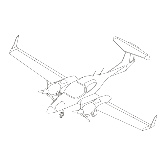
Diamond DA 42 NG Maintenance Manual (2340 pages)
Brand:
Diamond
| Category:
Aircrafts
| Size: 40 MB
Table of Contents
Table of Contents
3
List of Effective Pages
13
Table of Contents
43
Introduction
45
General
45
Revision Service
45
Warning, Cautions and Notes
45
Manual Configuration
46
Numbering System
47
Groups of Chapters
47
The Main Contents of each Group of Chapters
48
Page Numbering System
50
Figures
50
Record of Revisions
50
List of Effective
50
Manual Organization
53
Organization and Handling of the Manual
55
General
55
Applicability
55
Revisions
55
Temporary Revisions
55
Service Bulletins and Service Instructions
56
Concession-Reports and Non-Conformance-Reports
56
Document Notifications
56
Abbreviations
57
Conversion Factors and Abbreviations
59
Torque Conversion Factor
61
Supplemental Airplane Manuals
63
General Description
67
Airplane View
69
Equipment Data
72
Handling of Identification Data
76
Airworthiness Limitations
83
Certification Maintenance Requirements
83
Replacement Requirements
84
Time Limits and Maintenance Checks
93
Time Limits
99
Complete Aircraft Inspection
100
Scope of Maintenance Inspections
100
Component Time Limits
101
Airplane Life-Limited Components
103
Scheduled Maintenance Checks
107
Maintenance Checklist Organization
107
Flight-Line Checks
111
Post-Flight Check
111
Drain Holes Inspection Checklist and Report
113
Drain Holes Fuselage Diagram
119
Drain Holes Canopy Diagram
121
Drain Holes Door Diagram
122
Drain Holes Horizontal Stabilizer, Elevator and Elevator Trim Tab
123
Drain Holes Rudder Diagram
124
Drain Holes Rudder Diagram (if MÄM 42-600 Is Installed)
125
Drain Holes Center Wing Diagram
126
Drain Holes Wings, Flaps and Ailerons Diagram
127
Maintenance Checklist da 42 NG Engines
129
General
129
Preparation
129
Engine Ground Test
130
Maintenance Checklist Engines
131
Inspection Items, RH Engine
139
Inspection Items, LH Propeller
146
Maintenance Checklist Airframe
147
Inspection Items, Exterior Fuselage, General
147
Exterior of the Fuselage
147
Inspection Items, Nose Landing Gear
148
Inspection Items, Main Landing Gear
150
Inspection Items, Wheels
152
Inspection Items, Fuselage Nose
153
Inspection Items, Cabin, General
156
Inspection Items, Canopy, Doors, and Windows
157
Inspection Items, Cabin Structure
159
Inspection Items, Instrument Panel and Electrical System in Cabin
160
Inspection Items, Flight Control System in Cabin
162
Inspection Items, Other Cockpit Controls
166
Inspection Items, Cabin, Miscellaneous
168
Interior Structure of the Rear Fuselage
170
Inspection Items, Control System in the Rear Fuselage
173
Inspection Items, Miscellaneous Items in the Rear Fuselage
174
Inspection Items, Center Wing, Exterior
176
Inspection Items, Center Wing, Interior
178
Inspection Items, Inner Flaps
179
Inspection Items, Tail, General
180
Inspection Items, Structure of the Vertical Tail
181
Inspection Items, Structure of the Horizontal Stabilizer
182
Inspection Items, Rudder
184
Inspection Items, Rudder Hinges and Control System in Vertical Tail
185
Inspection Items, Elevator and Elevator Hinges
187
Inspection Items, Elevator Control System in Tail
188
Inspection Items, Miscellaneous Items in Tail
189
Inspection Items, Wings, General
190
Inspection Items, Wings, Structure
191
Inspection Items, Ailerons and Outer Flaps
193
Inspection Items, Fuel Tanks
195
Inspection Items, Wings, Miscellaneous
197
Inspection Items, General
198
Maintenance Report
203
Engine Ground Test Record
205
Check Flight Report
207
Major Structural Inspection Check Findings Report
213
Unscheduled Maintenance Checks
215
Hard Landing Check
215
General
215
Hard Landing Check Areas - Main Landing Gear
218
Hard Landing Check Areas - Nose Landing Gear
219
Gear up Landing Check
220
Propeller Strike
221
Engine Fire
222
Lightning Strike
224
Over Temperature
230
High Oil Consumption
230
Oil Pressure Loss
230
Hang Start
230
Overweight Landing Check
231
Dimensions and Areas
236
Dimensions and Areas
237
General
237
Dimensions Diagram
238
Dimensions Table
239
Adjustment Reports
241
Weight and Static Moments of Control Surfaces
241
Control Surface Adjustment Report - Flaps and Ailerons
242
Control Surfaces Adjustment Report - Elevator and Rudder
243
Control Surfaces Adjustment Report - Elevator Trim
244
Control Surfaces Adjustment Report - Rudder Trim
245
Adjustment Report, General Items (Metric Dimensions)
248
Adjustment Report, General Items (Imperial Dimensions)
249
Main Landing Gear Toe-In and Camber Report
250
Main Landing Gear Track and Camber
251
Lifting and Shoring - General
257
Jacking
259
Lifting the Airplane on Jacks - Diagram
260
Lifting the Airplane - Detail Steps/Work Items
261
Lowering the Airplane
262
Hoisting
263
Hoisting the Airplane - Diagram
264
Weighing
271
Level the Airplane Laterally for Weighing
272
Weighing Dimensions for Mechanical Scales under the Wheels
273
Weighing with Mechanical Scales under the Wheels
274
Leveling
279
Make the Airplane Level with Jacks
279
Level the Airplane Laterally
280
Level the Airplane Longitudinally
280
Level the Airplane with Jacks
281
Towing and Taxiing - General
287
Towing Procedure
289
Movement by Hand
290
Steering Bar or Tow Bar Attachment
290
Movement with a Tow Vehicle
291
Taxiing
293
The Safety Area for Taxiing the Airplane
294
Parking, Mooring and Storage
301
Parking and Storage
303
Long-Term Parking
305
Storage
307
Monthly Routine Check
308
Mooring
309
Location of Mooring Points on the Airplane
310
Return to Service
311
Placards and Markings
317
Replace a Placard
318
Exterior Placards and Markings
319
Design Example for Exterior Markings
320
Adhesive Strips Maintenance Practices
321
Safety Walk Template Positioning
323
Interior Placards and Markings
325
Interior Placards - Instrument and Control Panels
327
Placard Panels
328
How to Replace a Placard Panel
333
Servicing - General
337
General
339
Replenishment
341
Fuel System
341
Main Fuel Tanks
341
Auxiliary Fuel Tanks
341
General
341
Replenishment Points View
343
Refueling/Defueling
344
Defueling
345
Fuel Contamination Test
346
Engine Oil System
347
Replenish the Oil System
347
Engine Oil Filler/Dip-Stick View
348
Replenish the Gearbox Oil System
349
Engine Coolant Expansion Tank / Filler Cap View
350
Engine Coolant
352
Replenish the Engine Coolant
353
Brake System
355
Fill the Brake System Reservoirs
355
Ice Protection System
356
Fill the Deicing Fluid Tank
356
Examine the Tires and Measure the Pressure
357
Oxygen System
358
Filling the Oxygen Cylinder
358
Scheduled Servicing
361
General
361
Lubrication Schedule
362
Lubricant Specifications
364
Lubrication Points Diagrams
365
Unscheduled Servicing
367
Exterior Cleaning
367
Canopy and Transparency Cleaning
367
Interior Cleaning
367
General
367
Engine Cleaning
368
Snow and Ice Removal
368
Conservation of Exterior Parts
369
Anti-Corrosion Coating Check
369
Remove the Anti-Corrosion Coating
369
Apply the Anti-Corrosion Coating
370
Anti-Corrosion Coating Checklist
370
Anti-Corrosion Coating - Control Rod Flaps LH/RH
373
Anti-Corrosion Coating - Control Rod Ailerons LH/RH
374
Anti-Corrosion Coating - Main Landing Gear LH/RH
375
Anti-Corrosion Coating - Main Landing Gear Bay LH/RH
378
Anti-Corrosion Coating - Elevator and Elevator Trim System
379
Anti-Corrosion Coating - Elevator Controls
381
Anti-Corrosion Coating - Rudder Pedestal
382
Anti-Corrosion Coating - Rudder
383
Anti-Corrosion Coating - Nose Landing Gear
384
Anti-Corrosion Coating - Foot Step Screws
388
Standard Practices - Airframe
395
Bolt and Nut Types Used in the Airplane
396
Standard Torque Values
397
Special Torque Values
398
Torque Measurement
398
Standard Practices - Electrical
399
Thread Locking
399
Crimp Tools
400
Wires and Cables
400
Wire Marking
401
Testing Wires and Cables
401
Standard Practices - Engines
403
Standard Torque Values for Engine Bolts and Nuts
403
Standard Torque Values for Engine Pipe Plugs
404
Standard Torque Values for Engine Crush-Type Asbestos Gaskets
404
Standard Torque Values for Engine Flexible Hose (or Tube) Connections
405
Special Torque Values for the Engine
405
Installation and Tightening Torques of Worm Drive Clamps
406
Two Worm Drive Clamps
407
Tightening Torques for Worm Drive Clamps
409
Standard Practices - Center Wing
411
Routing in Center Wing - Overview
412
Routing in Center Wing Diagrams
413
Aileron Control System Troubleshooting
421
Heating and Ventilation
425
Heating and Ventilation
427
Cabin Heating and Canopy Defrosting
431
General
431
Description and Operation
431
Cabin Ventilation/Cooling
432
Air Conditioning Schematic Diagram
433
Air Distribution
435
General
435
Ventilation Air Distribution System Schematic Description
436
Ventilation
437
Cabin Heating and Defrost Air Distribution System Schematic
438
Heating and Defrosting
440
Air Conditioning Distribution System Troubleshooting
441
Trouble-Shooting
441
General
441
Replace a Heater Control Valve Forward Inner Control Cable
443
Maintenance Practices
443
General
443
LH Heater Valve Control Cables View
444
RH Heater Valve Control Cables
446
Replace a Heater Control Valve Aft Cable
449
Replace a Heater Control Valve Control Cable (if MÄM 42-739 Is Installed)
451
LH Heater Valve Control Cables (if MAM 42-739 Is Installed)
455
RH Heater Valve Control Cables (if MAM 42-739 Is Installed)
456
Test/Adjust a Heater Valve Control Cable
457
Heating
459
General
459
Heating System Diagram
460
Heating System Description and Operation
461
Air Conditioning Heating System Troubleshooting
463
Trouble-Shooting
463
General
463
Remove a Heat Exchanger Assembly
465
Maintenance Practices
465
General
465
Heat Exchanger Installation
466
Install a Heat Exchanger Assembly
470
Cooling (OAM 42-193/C or Earlier Installed)
473
Description
473
RACC System Schematic
474
RACC Control Panel
475
RACC System Operation
476
Control Panel in the Center Console Troubleshooting
477
Trouble Shooting
477
General
477
Remove/ Install the Central Unit (RACC)
479
Maintenance Practices
479
RACC Central Unit Installation
481
Remove/ Install the Central Unit
482
Central Unit - Front and LH Side View
483
Central Unit - Back and RH Side View
484
Remove/Install the Control Panel (RACC)
485
RACC - System Test Procedure
486
Remove/Install Parts of the Refrigerant Circuit
487
Charge the Refrigerant Circuit
488
Remove/Install the Compressor
489
Remove/Install the Filter/Drier Assembly
490
Remove/Install the Expansion Valve
491
Cooling (OÄM 42-193/D or Later Installed)
493
General
493
Description
493
RACC System Schematic (OAM 42-193/D or Later Is Installed)
494
RACC Control Panel (if OAM 42-193/D or Later Is Installed)
495
RACC Operation (if OAM 42-193/D or Later Is Installed)
496
Trouble Shooting
497
General
497
Maintenance Practices
499
RACC Central Unit Installation (OAM 42-193/D or Later Is Installed)
501
Remove/ Install the Central Unit
502
Central Unit - Front and LH Side (OAM 42-193/D or Later Is Installed)
503
Central Unit - Front and RH Side (OAM 42-193/D or Later Is Installed)
504
Remove/Install the Control Panel
505
RACC - System Test Procedure
506
Remove/Install Parts of the Refrigerant Circuit
507
Leakage Test of the Refrigerant Circuit
509
Remove/Install the Filter/Dryer Assembly
511
Temperature Control
513
General
513
Heater Valve Assembly View
514
Heater Valves Description and Operation
515
Air Conditioning Temperature Control Troubleshooting
517
Remove/Install a Heater Valve
519
Heater Valve Installation
521
Install a Heater Valve Assembly
522
Auto Flight
527
Auto Flight
529
General
529
Autopilot
531
General
531
Description
531
GFC 700 Autopilot Schematic Diagram
532
Roll Servo Installation
534
Remove/Install the Roll Servo
535
Maintenance Practices
535
General
535
Remove/Install the Roll Servo Clutch
536
Remove/Install the Pitch Servo
538
Pitch Servo Installation Diagram
539
Remove/Install the Pitch Servo Clutch
540
Pitch Trim Servo Installation Diagram
542
Remove/Install the Pitch Trim Servo
543
Remove/Install the Pitch Trim Servo Clutch
544
Remove/Install the Yaw Servo and the Yaw Servo Clutch
545
Yaw Servo Installation Diagram
546
Install the Yaw Servo, the Yaw Servo Clutch and Bridle Cable
547
Yaw Damper Cable Installation Diagram
549
Adjust the Bridle Cable Tension of the Roll and Pitch Servos
550
Adjust the Bridle Cable Tension of the Yaw Servo
551
Adjust/Check the Servo Clutch Torques
553
Mechanical Check of the Autopilot System (if OÄM 42-210 (GSM 86 Servo Mounts) Is Not Installed)
555
Mechanical Check of the Autopilot System (if OÄM 42-210 (GSM 86 Servo Mounts) Is Installed)
555
Slip Clutch Override Procedure
556
Communications
559
Communication System Description
561
Speech Communication
563
General
563
Garmin 1000 Primary Flight Display Panel
564
Description
565
Speech Communication System Troubleshooting
567
Trouble-Shooting
567
General
567
Speech Communication System Maintenance
569
Remove/Install a COM VHF Antenna
569
Maintenance Practices
569
General
569
Install a COM VHF Antenna
570
Remove/Install a PTT Switch
571
Satellite Transceiver System (if OAM 42-213 Is Carried Out)
573
General
573
Description and Operation
573
Satellite Transceiver System Troubleshooting
575
Trouble-Shooting
575
General
575
Remove/Install the GSR 56 Satellite Transceiver
577
Maintenance Practices
577
General
577
Remove/Install the Iridium Antenna
578
Test of the GSR 56 Satellite Transceiver
579
Audio Integration
581
General
581
Audio Control Panel View
582
Audio Control Panel Description
583
Description and Operation
583
Audio Integrating System Troubleshooting
587
Trouble-Shooting
587
General
587
Remove/Install the GMA 1347 Audio Control Panel
589
Maintenance Practices
589
General
589
Static Discharging
591
General
591
Description
591
Static Discharge Wick Locations Diagrams
592
Static Discharge Wick Installation
593
Maintenance Practices
593
General
593
Replace a Static Discharge Wick
594
Electrical Power
597
Electrical Power - General
601
Electrical Schematic (Simplified)
602
Electrical System Description and Operation
604
Main Battery
604
Alternators
604
External Power Connector
604
Power Supply Control
607
Battery Relay/External Power Relay
607
Starter Relay
607
Bus Structure
607
Relay Locations in the Relay Box View
608
Relay Box Bus
609
Hot Bus
609
LH Main Bus
609
RH Main Bus
609
LH ECU Bus
610
RH ECU Bus
610
Avionics Bus
610
Avionics Master Control System
610
Avionics Master Relay
611
Elect. Master Switch/Start Switch
611
Engine Master LH / RH
611
Alternator LH and Alternator RH Switches
611
DC Generation
613
General
613
DC Generation Schematic Diagram
614
Alternator Relays
617
Alternator Current Sensors
617
Alternator Regulators
617
ECU Backup Batteries
617
Description and Operation
617
DC Generation System Troubleshooting
619
Trouble-Shooting
619
General
619
Electrical Safety
621
Maintenance Practices
621
General
621
ECU Backup Batteries Installation (RH)
622
ECU Backup Batteries Installation (LH)
623
LH/RH Alternator Relay Installation
624
ECU Backup Battery Installation
625
Remove/Install an Alternator Relay
626
Install an Alternator Relay
627
Remove/Install an ECU Backup Battery
628
Battery Systems
631
Main Battery Description and Operation
631
General
631
Main Battery Installation
632
Battery System Troubleshooting
633
Safety Precautions on Battery
635
Maintenance Practices
635
General
635
Remove/Install the Main Battery
636
Disconnect/Connect the Main Battery for Maintenance
638
Main Battery Relay Installation
640
Remove/Install the Battery Relay
641
Starter Relay Functional Test
643
Emergency Power
645
General
645
Description
645
Emergency Battery System Troubleshooting
647
Trouble-Shooting
647
General
647
Maintenance Practices
649
General
649
Remove/Install the Emergency Battery Pack
649
Emergency Battery Pack View
650
Install the Battery Pack
651
Additional Alternator
653
General
653
Additional Alternator Electrical System Schematic Diagram
654
Additional Alternator Excitation Battery
655
Additional Alternator Regulator
655
Description and Operation
655
Additional Alternator Electrical System Troubleshooting
657
Trouble Shooting
657
General
657
Additional Electrical Generating System Maintenance
659
Maintenance Practices
659
General
659
Electrical Safety
659
Remove/Install the AUX POWER Switch
660
Remove/Install the Additional Alternator Regulator
661
Install the Voltage Regulator
662
External Power Description
663
External Power Relay
663
General
663
Description and Operation
663
External Power Supply System Schematic
664
External Power Operation
665
External Power System Troubleshooting
667
Trouble-Shooting
667
General
667
Maintenance Practices
669
General
669
Electrical Safety
669
External Power Relay View
670
Remove/Install the External Power Relay
671
Install the External Power Relay
672
DC Electrical Load Distribution
673
General
673
Electrical System Bus Structure Simplified Diagrams
674
Location of Electrical Switches and Circuit Breakers
676
DC Electrical Distribution System Troubleshooting
677
Trouble-Shooting
677
General
677
DC Load Distribution System Maintenance
679
Maintenance Practices
679
General
679
Electrical Safety
679
Avionics Master Relay Installation
680
Remove the Avionics Master Relay
681
Install the Avionics Master Relay
681
Remove/Install a Circuit Breaker
682
Install a Circuit Breaker
683
Remove/Install an Instrument Panel Switch
684
Install a Clip-Secured-Type Instrument Panel Switch
685
Remove a Nut-Secured-Type Instrument Panel Switch
686
Install a Nut-Secured-Type Instrument Panel Switch
687
Equipment/Furnishings
691
Equipment Furnishings
693
General
693
Cabin Equipment View
694
Flight Compartment
695
General
695
Pilot’s Seat Installation
696
Fixed Pilots’ Seats
699
Pilots’ Seats with Adjustable Backrest
699
Description and Operation
699
Passenger Seat
700
Crash Elements
700
Passenger Seat Installation
701
Safety Harness Installation
702
Safety Harness Description
703
Fabric Wall Panels
703
Instrument Panel Cover
703
Center Console Panel
704
Remove/Install a Pilot’s Seat
705
Maintenance Practices
705
General
705
Additional Maintenance Practices for Seats with Adjustable Backrest
708
Test the Lumbar Support Mechanism of a Front Seat
710
Adjust the Friction of the Backrest
710
Visual Inspection of the Adjustment Mechanism
711
Remove/Install a Pilot’ S Seat Access Panel
713
Adjustable Backrest Assembly
714
Seat Adjustment Mechanism View
715
Adjustable Backrest Assembly View
716
Disassemble/Assemble the Adjustable Backrest Mechanism
717
Arrangement of the Fitting Seat, Fitting Backrest and Screws
718
Remove Backrest Assembly from Seat
719
Disassemble the Adjustable Backrest Mechanism
719
Assemble the Adjustable Backrest Mechanism
720
Assemble the Adjustable Backrest Mechanism (Optional, OAM 42-259)
722
Assemble a Pilots’ Seat
723
Remove/Install the Passenger Seat
724
Remove/Install a Safety Harness (if OÄM 42-324 Is NOT Installed)
726
Remove/Install the Instrument Panel Cover
728
Cleaning
729
Remove/Install the Short Baggage Extension (OÄM 42-207 Installed)
729
Aft Baggage Compartment
731
General
731
Description
733
Remove/Install the Access Panel in the Baggage Compartment Floor
735
Maintenance Practices
735
General
735
Remove/Install the Aft Baggage Compartment
737
Emergency Equipment
739
General
739
Description
739
ELT Main Components View
740
Description of the Artex ME406 ELT
741
Description of the Kannad 406 AF-Compact ELT
742
ELT Troubleshooting
743
General
743
Remove/Install the ELT
745
Maintenance Practices
745
General
745
ELT Installation (Standard Equipment)
746
ELT Battery Pack Installation
748
Replace the ELT Battery Pack
749
Remove/Install the Artex ME 406 or Kannad 406 AF-Compact ELT
751
Artex ME406 ELT Installation
752
Kannad 406 AF-Compact ELT Installation
753
Install the Artex ME406 or Kannad 406 AF-Compact ELT
754
Battery Pack Installation - Artex ME406
755
Replace the ELT Battery Pack of the Artex ME406
756
Remove/Install the ELT RCPI
758
ELT Functional Test
760
Kannad 406 AF-Compact ELT Functional Test
761
Fire Protection
767
General
767
Fire Extinguisher Installation
768
Fire Extinguisher Description
769
Engine Overheat Detector Installation
770
Overheat Detector Description
771
Fire Protection System Troubleshooting
773
Trouble-Shooting
773
General
773
Remove/Install an Engine Overheat Detector
775
Maintenance Practices
775
General
775
Overheat Detector Test
776
Flight Controls
779
Flight Controls
785
General
785
Flight Controls Description
786
Control Surfaces View
787
Pushrods
788
Control Rigging
788
Standard Control Pushrod View
789
Push-Rod Adjustment
791
Maintenance Practices
791
General
791
Remove/Install Levers or Bellcranks
792
Remove/Install a Control Stick
794
LH Control Stick and RH Stick Lever
795
Control Sticks View
796
Install a Control Stick
797
Measure the Play in a Hinge
798
Flight Controls - Aileron and Tabs
799
General
799
Aileron Controls in the Fuselage View
800
Aileron Controls in the Wing
802
Aileron Controls Description
803
Aileron Controls Operation
804
Aileron Controls Troubleshooting
805
Trouble-Shooting
805
General
805
Aileron Control System Test for Correct Range of Movement
807
Maintenance Practices
807
General
807
Aileron Control System Adjustments
810
Aileron Pushrod Access
813
Aileron Bellcrank and Lever Access
813
Flight Controls - Rudder
815
General
815
Rudder Control System View
816
Description
817
Rudder Pedal Assembly
818
Rudder Pedal Assembly with Electric Adjustment View
819
If You Move the Left Rudder Pedal Forward
820
Operation
820
Rudder Controls in the Cockpit
821
Rudder Controls Manual Adjustment
822
Rudder Controls Electrical Adjustment
822
Rudder Controls in the Fuselage
823
Rudder Control System Troubleshooting
825
Trouble-Shooting
825
General
825
Rudder Control System Test for Correct Range of Movement
827
Maintenance Practices
827
General
827
Rudder Control System Adjustments
829
Remove/Install the Rudder Control Cables
832
Install the Rudder Control Cables (Front Cables)
833
Remove the Fuselage Rudder Control Cables (Rear Cables)
836
Install the Fuselage Rudder Control Cables (Rear Cables)
837
Remove/Install the Pulleys
840
Rudder Control Cable and Yoke Access
842
Flight Controls - Rudder Trim
843
General
843
Rudder Trim Control System - Main Components View
844
Rudder Trim Handwheel Assembly
845
Flexible Cable
845
Description
845
Trim Tab Actuator Assembly
846
Trim Control System Operation
846
Trouble-Shooting
847
General
847
Rudder Trim-Tab Control System Test for Correct Range of Movement
849
Adjust the Rudder Trim-Tab Control System
849
Maintenance Practices
849
General
849
Adjust the Rudder Trim Tab Control System
852
Flight Controls - Elevator
857
General
857
Elevator Control Installation in the Cockpit
858
Elevator Controls Description
859
Elevator Controls in the Rear Fuselage
860
Elevator Controls Operation
861
If You Move the Control Stick Forward
861
If You Move the Control Stick Aft
861
Variable Elevator Stop View
862
Elevator Control System Troubleshooting
863
Trouble-Shooting
863
General
863
Elevator Control System Test for Correct Range of Movement
865
Maintenance Practices
865
General
865
Elevator Control Test Procedure Using the Protractor
867
Elevator Control System Adjustments
869
Elevator Angle Limits Table
870
Elevator Angle Measurement
871
Remove/Install the Variable Elevator Stop Assembly
872
Install the Variable Elevator Stop Assembly
873
Test/Adjust the Variable Elevator Stop
874
Operational Test of the Variable Elevator Stop
875
Operational Test of the STICK LIMIT Caution Message
876
Elevator Pushrod Access
877
Elevator Bellcrank and Lever Access
877
Stall Warning System
879
General
879
Description and Operation
879
Stall Warning System Troubleshooting
881
Trouble-Shooting
881
General
881
Remove/Install the Stall Warning Switch (Lift Detector)
883
Maintenance Practices
883
General
883
Equipment
883
Remove/Install the Stall Warning Horn
885
Flight Controls - Elevator Trim-Mechanical
887
General
887
Elevator Mechanical Trim Mechanism in the Cockpit View
888
Trim Handwheel Assembly
889
Description
889
Trim Tab Actuator Assembly Description
891
Operation
891
Emergency Operation
891
Elevator Mechanical Trim Control System Troubleshooting
893
Trouble-Shooting
893
General
893
Maintenance Practices
895
General
895
Elevator Mechanical Trim Control System Test for Correct Range of Movement
895
Elevator Mechanical Trim Control System Adjustment
898
Elevator Mechanical Trim Friction Damper Adjustment Procedure
900
Elevator Mechanical Trim Handwheel Friction Damper Adjustment
902
Flight Controls - Elevator Trim - Electrical
903
Pilot’s Control Stick Switch
903
Elevator Trim Servo
903
General
903
Description
903
Elevator Electrical Trim Control System Troubleshooting
905
Trouble-Shooting
905
General
905
Maintenance Practices
907
General
907
Flight Controls - Flaps
909
General
909
Flap Control System in the Fuselage
910
Flap Control System Description
911
Flap Actuator
911
Push-Rods and Bellcranks
911
Flap Push-Rods and Bellcranks in the Wings
912
Flap Electrical Control
913
Flap Actuator Installation
914
Flap Control System Operation
915
Flap Control System Fail-Safe Properties
915
Doc # 7.02.15
915
Flap Electrical Control System
916
Flap Control System Troubleshooting
917
Trouble-Shooting
917
General
917
Remove/Install the Flap Actuator
921
Maintenance Practices
921
General
921
Test the Flap Control System
923
Adjust the Flap Control System
926
Adjust the Flap Preload
929
Flap Preload Adjustment
931
Flap Push-Rod Access
932
Flap Bellcrank and Lever Access
932
Fuel
935
Fuel System General Information
939
Fuel System Schematic Diagram Without Auxiliary Tanks
940
Main Fuel Tanks Description
942
Auxiliary Fuel Tanks Description
943
Auxiliary Fuel System Schematic Diagram
944
Fuel System Normal Operation
946
Fuel Pumps
947
Fuel Transfer
947
Fuel System Emergency Operation
948
Fuel Drains
948
Fuel Storage System
949
General
949
Main Fuel Tank Installation
950
Main Fuel Tank Description
951
Fuel Filler Assembly LH
952
Fuel Filler Assemblies
953
Auxiliary Fuel Tank Description
954
Auxiliary Fuel Tank Installation
955
Auxiliary Fuel Tank Filler
956
Auxiliary Fuel Tank Filler Installation
957
Fuel Storage System Troubleshooting
959
Trouble-Shooting
959
General
959
Remove/Disassemble a Main Fuel Tank Assembly
961
Maintenance Practices
961
General
961
Assemble/Install a Main Fuel Tank Assembly
965
Install a Main Fuel Tank Assembly
969
Remove/Install an Auxiliary Fuel Tank
971
Install an Auxiliary Fuel Tank
973
Fuel Distribution
975
General
975
Fuel Distribution System Schematic Without Auxiliary Tanks
976
Fuel Distribution System Normal Operation
977
Description
977
Fuel Distribution System Schematic with Auxiliary Tanks
978
Fuel Transfer Operation
979
Auxiliary Fuel Supply to the Main Fuel Tank
980
Fuel Distribution System Components
981
Flexible Hoses
981
Fuel Transfer/Shut-Off Valves
981
Fuel Filter Assembly
982
Low Pressure Fuel Pump Assembly
982
Fuel Cooler
982
Fuel Pressure Pulsation Damper
982
Fuel Distribution System Troubleshooting
983
Remove a Fuel Transfer/Shut-Off Valve
985
Fuel Transfer/Shut-Off Valve Installation
987
Install a Fuel Transfer/Shut-Off Valve
988
Remove the Fuel Selector Gearbox
989
Install the Fuel Selector Gearbox
991
Fuel Filter Assembly View
993
Remove/Install the Fuel Filter Body
994
Install the Fuel Filter Body
995
Fuel Pumps Assembly
996
Remove/Install the Fuel Pre-Filters
998
Fuel Pre-Filter Assembly
999
Remove/Install the Fuel Pre-Filters
1000
Remove/Replace/Install the Fuel Pressure Pulsation Damper
1001
Fuel System Components Firewall Forward LH and RH Engine
1002
Replace the Fuel Pressure Pulsation Damper
1003
Install the Fuel Pressure Pulsation Damper Housing Assy
1004
Remove/Install the Low Pressure Fuel Pumps
1004
Test the Solenoid Valve/Check Valve in the Fuel Transfer Line (if Auxiliary Tanks Installed)
1007
Remove/Install a Fuel Cooler
1008
Fuel Cooler Installation
1009
Install a Fuel Cooler
1010
Test the Crossfeed Position of a Fuel Selector Valve
1011
Remove/Install an Inline Filter
1012
Install an Inline Filter
1013
Test the Auxiliary Fuel Transfer System
1014
Fuel Distribution (if MAM 42-600 Is Installed)
1015
General
1015
Description
1017
Fuel Distribution System Components
1021
Trouble-Shooting
1023
General
1023
Remove/Install a Fuel Transfer/Shut-Off Valve
1025
Maintenance Practices
1025
General
1025
Remove/Install the Fuel Selector Gearbox
1029
Fuel Filter Assembly (if MAM 42-600 Is Installed)
1033
Remove/Install the Fuel Filter Body
1034
Remove/Install the Fuel Pre-Filters
1035
Clean the Pre-Filters
1036
Fuel Pre-Filter Assembly (if MAM 42-600 Is Installed)
1037
Remove/Replace/Install the Fuel Pressure Pulsation Damper
1038
Remove/Install the Low Pressure Fuel Pumps
1042
Fuel Pumps Assembly (if MAM 42-600 Is Installed)
1044
Test the Solenoid Valve/Check Valve in the Fuel Transfer Line (if Auxiliary Tanks Installed)
1045
Test the Crossfeed Position of a Fuel Selector Valve
1046
Remove/Install an Inline Filter
1047
Fuel Indicating
1051
Fuel Quantity
1051
General
1051
Description
1051
Operation
1051
Fuel Temperature
1052
Fuel Low-Level
1052
Fuel Indicating System Components
1053
Fuel Indicating System Troubleshooting
1055
Trouble-Shooting
1055
General
1055
Remove/Install a Fuel Quantity Probe
1057
Maintenance Practices
1057
General
1057
Remove/Install a Fuel Temperature Sensor
1059
Install a Fuel Temperature Sensor
1060
Remove/Install a Fuel Low-Level Sensor
1061
Install a Fuel Low-Level Sensor
1062
Remove/Install a Fuel High-Level Shut-Off Sensor
1063
Install a Fuel High-Level Shut-Sensor
1064
Hydraulic Power
1067
Hydraulic Power
1070
Main Hydraulic Power
1071
General
1071
Description
1071
Main Hydraulic Power Troubleshooting
1073
Trouble-Shooting
1073
General
1073
Check the Hydraulic Fluid Level of the Hydraulic System
1079
Maintenance Practices
1079
Hydraulic Supply and Control Assembly
1080
Fluid Change of the Hydraulic System
1081
Fluid Change of Hydraulic System from Aero Shell Fluid 41 to AMG-10
1083
Position of the Hydraulic Fluid Placard
1083
Depressurize the Hydraulic System
1084
Bleed the Hydraulic System
1085
Drain Fluid from the Hydraulic System
1087
Remove/Install the Relay
1089
Remove/Install the Hydraulic Reservoir
1090
Install the Hydraulic Reservoir
1091
Hydraulic Reservoir Assembly View
1092
Remove the Hydraulic Supply and Control Assembly
1093
Install the Hydraulic Supply and Control Assembly
1095
Remove/Install Hydraulic Pump
1098
First Fill/Replenishment of the Hydraulic System
1100
Fluid Capacity
1100
Normal Operation Test of the Hydraulic System
1103
Charging Time of the Empty Accumulator
1103
Extending and Retracting Time of the Landing Gear
1104
Differential Pressure Mode for Retracting of the Landing Gear
1105
Internal Leak Tightness
1105
Emergency Operation Function Test of the Hydraulic System
1106
Emergency Extension Test
1106
Leak Tightness Test of the Hydraulic System
1108
Checklist for External Leakage
1111
Pump Pressure Switch and Pressure Limitation Valve Operation Test
1112
Maintain Hydraulic Reservoir Filter
1116
Replace/Maintain the High Pressure Filter
1118
Replace the Dump Valve
1119
Replace the Pressure Relief Valve / Pump Pressure Switch
1121
Replace/Check a Solenoid Valve
1123
Electric States of the Solenoid Valves
1124
Replace the Accumulator Charging Valve
1124
Replace the Flow Regulation Valve
1126
Remove/Install/Disassemble/Assemble Hydraulic Control Block
1127
Install the Hydraulic Control Block
1128
Disassemble Hydraulic Control Block
1129
Assemble Hydraulic Control Block
1130
Hydraulic Control Block View
1131
Bleed/Remove/Install the Accumulator
1132
Remove the Accumulator
1133
Install the Accumulator
1134
Check the Accumulator
1134
Hydraulic Accumulator Installation Diagram
1135
Accumulator Testing Procedure
1136
Charge the Hydraulic Accumulator with Nitrogen
1138
Ice Protection System - General Information
1145
Ice Protection System - Mechanical Schematic
1146
Ice Protection System - Electrical Schematic
1148
Description
1150
De-Icing Fluid Tank
1151
Main Pump Assembly
1152
Airframe Ice Protection System
1152
High Pressure Sensor
1152
De-Icing Fluid Filters
1152
Wing and Propeller Ice Protection System
1153
Empennage Ice Protection System
1154
Windshield De-Icing System
1155
Ice Protection Control System
1155
Windshield De-Icing Pumps
1155
De-Ice Control Box
1155
Ice Protection System Operation
1156
Handling of Porous Panels
1158
Ice Protection System Troubleshooting
1159
Trouble-Shooting
1159
General
1159
Ice Protection System Maintenance
1161
Ice Protection System Operational Test
1161
Maintenance Practices
1161
General
1161
Annunciation Checkout
1162
Fluid Emission Test Preparation
1162
Windshield Spraybar Check
1163
Main De-Ice Panel Test
1163
Cycle Time Test
1164
Drain the Ice Protection System
1165
Ice Light/Annun Test
1165
Remove/Install the De-Icing Fluid Tank
1166
Drain the Ice Protection System
1166
Remove/Install the De-Icing Fluid Inlet Strainer
1168
Install the De-Icing Fluid Inlet Strainer
1169
Remove a De-Icing Metering Pump
1170
Install a De-Icing Metering Pump
1170
Replace the Filter Cartridge or Windshield Pump or Solenoid Valve
1171
Bleed the De-Icing System
1172
Bleed the De-Icing System
1173
Purge the De-Icing System
1174
Remove a Proportioning Unit from the Nacelle
1174
Replace an Ice Protection Porous Panel
1175
Install a Proportioning Unit to the Nacelle
1175
Replace De-Icing Fluid Nylon Tubing
1176
Replace Ice Protection Control Box
1176
Remove/Install the High Pressure Switch
1177
Install High Pressure Switch
1178
High Pressure Switch Values
1178
Remove/Install the Low Pressure Switch Proportioning Unit
1180
Install the Low Pressure Switch Proportioning Unit
1181
Remove/Install a Low Pressure Switch in the Horizontal Tail
1182
Install a Low Pressure Switch in the Horizontal Tail
1183
Indicating Systems
1187
Indicating Systems
1189
General
1189
Instrument and Control Panels
1191
General
1191
Instrument Panel View
1192
Instrument Panel (with OAM 42-270) View
1193
Instrument Panel Description
1194
Center Console
1195
Center Console Description
1196
De-Ice Control Panel Description
1197
Trouble-Shooting
1199
General
1199
Remove/Install the Engine Control Assembly
1201
Maintenance Practices
1201
General
1201
Independent Instruments
1207
General
1207
Central Computers
1209
General
1209
Integrated Cockpit System Schematic Diagram
1210
Primary Flight Display (PFD)
1211
Description
1211
Garmin G1000 Display Screens and Audio Integrating Unit
1212
Primary Flight Display
1214
Attitude Indicator
1214
Multi-Function Display (MFD)
1217
Multi Function Display
1220
MFD Full EIS Page
1220
General
1223
ICS Maintenance
1225
Remove/Install a GDU 10XX Display
1228
GDU 10XX Display Unit Installation
1229
GIA 63 W Integrated Avionics Unit (IAU) Installation
1231
Remove/Install a GIA 63 W Integrated Avionics Unit (IAU)
1232
Transponder Installation
1233
Remove/Install the GTX33/335 R Transponder
1234
GRS 77 Attitude, Heading and Reference Unit (AHRS) Installation
1235
GRS 79 Attitude, Heading and Reference Unit (AHRS)
1236
Remove the GRS 7X Attitude, Heading and Reference Unit (AHRS)
1237
Install the GRS 7X Attitude, Heading and Reference Unit (AHRS)
1237
GDC 7X Air Data Computer (ADC) Installation
1239
Remove/Install the GDC 7X Air Data Computer (ADC)
1240
Install the GDC 7X Air Data Computer (ADC)
1241
Remove/Install the GEA 71 Processor
1242
Remove the GMU 44 Magnetometer
1244
Magnetometer Assembly Installation
1245
Install the GMU 44 Magnetometer
1246
G1000 Magnetometer Calibration
1247
Remove/Install the De-Ice Control Panel
1249
Landing Gear
1253
Landing Gear
1257
General
1257
Description
1257
Landing Gear - Main Components View
1259
Operation on the Ground
1260
Operation in the Air
1260
Emergency Operation
1260
Main Landing Gear
1261
General
1261
Description
1261
Operation
1261
Main Landing Gear Troubleshooting
1263
Trouble-Shooting
1263
General
1263
Main Landing Gear Maintenance
1265
Maintenance Practices
1265
General
1265
Main Landing Gear Leg Assy View
1266
Remove/Install the Main Gear Leg (Completely with Axle and Brake Unit)
1267
Main Landing Gear Installation
1271
Removal of the Main Landing Gear Leg
1272
Install the Main Landing Gear Leg
1273
Disassemble/Assemble a Main Landing Gear Leg
1276
Assemble Main Landing Gear Leg
1277
Remove a Joint on Main Landing Gear Leg
1278
Install a Joint on Main Landing Gear Leg
1280
Fill/Charge the Damper Assemblies on the Main Gear Legs
1281
Fluid Change from Aero Shell Fluid 41 to AMG-10
1286
Position of the Hydraulic Fluid Placard - Main Landing Gear Dampers
1287
Required Strut Extension of the Main Gear Damper Assemblies
1288
Remove/Install a Main Landing Gear Damper
1289
Install a Main Landing Gear Damper
1290
Disassemble/Assemble Main Landing Gear Damper
1291
Assemble Main Landing Gear Damper
1293
Remove/Install a Main Landing Gear Door
1295
Main Landing Gear Door View
1296
Install a Main Gear Door
1297
Remove/Install the MLG Folding Stay / Hydraulic Actuator
1298
Main Landing Gear Folding Stay View
1300
Install the Folding Stay / Hydraulic Actuator
1301
Disconnect/Connect the MLG Folding Stay Assembly
1302
Connect the Folding Stay Assembly to the MLG
1305
Test Main Landing Gear (Wheel Track and Camber)
1307
Wheel Track Table
1309
Main Gear Wheel Track View
1310
Adjustment of the Main Landing Gear Wheel in Retracted Position
1311
Check of Main Landing Gear Door Pre-Load
1312
Main Landing Gear Tire Clearance Measurement
1314
Main Landing Gear Door Measurement
1315
Main Landing Gear Door Pre-Load Measurement
1316
Nose Landing Gear
1317
General
1317
Description
1317
Nose Gear Assembly View
1318
Nose Landing Gear Operation
1319
Nose Gear Leg Assembly View
1320
Nose Landing Gear Troubleshooting
1321
Trouble-Shooting
1321
General
1321
Nose Landing Gear Maintenance
1323
Maintenance Practices
1323
General
1323
Nose Landing Gear Leg View
1324
Remove/Install the Nose Landing Gear Leg
1325
Install Nose Landing Gear Leg
1327
Remove/Install a Nose Gear Door
1329
Install a Nose Gear Door
1330
Remove/Inspect/Install Nose Landing Gear Damper Assembly
1331
Inspect the Nose Landing Gear Damper Assembly
1333
Install the Nose Landing Gear Damper Assembly
1334
Required Strut Extension of the Nose Landing Gear Damper Assembly
1335
Fill/Charge the Damper Assembly on the Nose Gear Leg
1336
Position of the Hydraulic Fluid Placard - Nose Landing Gear Damper
1341
Disconnect the Nose Landing Gear Folding Stay Assembly
1342
Nose Landing Gear Extension and Retraction
1347
Connect the Nose Landing Gear Folding Stay Assembly
1349
Nose Landing Gear Actuator View
1352
Remove the Nose Landing Gear Actuator
1353
Nose Landing Gear Actuator Measurements
1356
Install the Nose Landing Gear Actuator
1357
Remove/Install the Nose Landing Gear Mounting Bracket
1361
Install the Nose Landing Gear Mounting Bracket
1362
Extension and Retraction
1363
General
1363
Description
1363
Extension and Retraction System Main Components
1364
Main Landing Gear - Extension and Retraction
1365
Selector Handle
1366
Emergency Extension System
1366
Nose Landing Gear - Extension and Retraction
1367
Landing Gear Operation
1368
‘Differential Pressure’ Retraction Operation Diagram
1369
Hydraulic Schematic Diagram - ‘Full Pressure’ Retraction Operation
1370
Hydraulic Schematic Diagram - Normal Extension Operation
1371
Hydraulic Schematic Diagram - Emergency Extension Operation
1373
Landing Gear Extension and Retraction System Troubleshooting
1375
Trouble-Shooting
1375
General
1375
Landing Gear Extension and Retraction System Maintenance
1377
Maintenance Practices
1377
General
1377
Main Landing Gear Hydraulic Actuator Installation
1378
Landing Gear Hydraulic Actuator Assembly
1379
Hydraulic Actuator Alignments
1380
Disassemble/Assemble the Actuator
1381
MLG Actuator Measurement
1382
Assemble the Actuator
1383
Landing Gear Extension and Retraction Test (Normal Extension)
1385
Landing Gear Emergency Extension System Test
1388
Wheels and Brakes
1391
General
1391
Main and Nose Wheel Assemblies View
1392
Description - Main Wheels
1393
Description - Nose Wheel
1393
Wheel Brake System Schematic Diagram
1394
Description - Brake System
1395
Main Wheel Brake Assembly
1396
Operation - Brake System
1397
Wheels and Brakes Troubleshooting
1399
Trouble-Shooting
1399
General
1399
Wheels and the Main Brake System Components Maintenance
1401
Maintenance Practices
1401
General
1401
Remove/Install a Main Wheel
1401
Install a Main Wheel
1404
Remove/Install the Nose Wheel
1406
Install the Nose Wheel
1408
Disassemble/Assemble Main/Nose Wheel
1409
Assemble Main/Nose Wheel
1410
Remove/Install Brake System Components - General
1411
Remove/Install a Brake Master Cylinder
1412
Brake Master Cylinder Installation
1414
Parking Brake Valve Installation
1416
Remove/Install the Parking Brake Valve
1417
Install the Parking Brake Valve
1418
Remove/Install a Brake Caliper
1419
Brake Caliper Installation
1420
Bleed the Wheel Brake System
1422
Replace the Brake Friction Linings
1424
Steering
1427
General
1427
Nose Wheel Steering View
1428
Steering Linkage
1429
Linkage Buffer
1429
Centering Unit
1429
Description
1429
Steering Operation
1430
Nose Wheel Steering Troubleshooting
1431
Trouble-Shooting
1431
General
1431
Maintenance Procedures
1433
General
1433
Remove/Install the Steering Linkage
1433
Install the Steering Linkage
1434
Remove/Install the Centering Unit
1435
Install the Centering Unit
1436
Nose Wheel Steering Friction Test
1437
Position and Warning
1439
General
1439
Description
1439
Landing Gear Electrical Schematic Diagram
1440
Landing Gear Selector
1441
Weight-On-Wheels Switches
1441
Folding-Stay Switches
1441
Landing Gear Retracted Switches
1441
Engine Power Lever Switches
1442
Control Relay and Circuit Breakers
1442
Position and Warnings System Troubleshooting
1443
Trouble-Shooting
1443
General
1443
Position and Warning System Maintenance
1445
Maintenance Practices
1445
General
1445
Remove/Install an Engine Power Lever Switch
1445
Engine Power Lever Switch Installation
1446
Position and Warning Switches - Main Landing Gear
1448
Replace a Landing Gear Switch (Excluding the Nose Gear Folding Stay Switch)
1449
Position and Warning Switches - Nose Landing Gear
1450
Replace a Nose Gear Folding Stay Switch
1452
Adjust Landing Gear Indication Micro Switches
1453
Adjust Main/Nose Gear Retract Switches and Differential Switch
1453
Adjust Landing Gear Folding Stay and Weight on Wheel Switch
1455
Cleaning and Maintaining the Micro Switches
1455
Test the Landing Gear Position and Warning System
1456
Lights
1461
General
1463
Flight Compartment View
1464
Exterior Lights
1465
Lights - Flight Compartment
1467
Map/Reading Lights
1467
Instrument Panel Flood Lighting
1467
General
1467
Description
1467
Instrument Lights (Placard Lights)
1470
Flight Compartment Lighting System Troubleshooting
1471
Trouble-Shooting
1471
General
1471
Remove a Map/Reading Light Assembly
1473
Install a Map/Reading Light Assembly
1473
Maintenance Practices
1473
General
1473
Replace a Filament in a Map/Reading Light Assembly (if MÄM 42-1024 Is Not Installed)
1474
Remove/Install a Map/Reading Light Assembly (if MÄM 42-1024 Is Installed)
1474
Replace Filament in Map/Reading Light Assembly (MAM 42-1024 Installed)
1475
Remove/Install a Dimmer Switch
1476
Install a Dimmer Switch
1477
Replace the Flood Light/Instrument Light Strip
1478
Solid State Inverters for the Instrument and Flood Lights
1480
Remove/Install a Solid State Inverter for the Flood Light/Instrument Lights
1481
Install a Solid State Inverter
1482
Exterior Lights of the da 42 NG
1483
General
1483
Description
1483
Wing Tip Light Unit and Strobe Power Unit View
1484
Wing Tip-Light Unit View (if OAM 42-222 Is Installed)
1485
Position Lights (if OAM 42-222 Is NOT Installed)
1486
Strobe Light (Anti-Collision Light - ACL)
1486
Landing Light
1487
Taxi Light
1487
Landing and Taxi Light Installation
1488
Exterior Lighting System Troubleshooting
1489
Trouble-Shooting
1489
General
1489
Exterior Lighting System Maintenance
1491
Maintenance Practices
1491
General
1491
Remove/Install the Taxi Light
1491
Install the Taxi Light
1492
Remove/Install the Landing Light
1493
Install the Landing Light
1494
Remove/Install an Electronic Controller
1495
Install an Electronic Controller
1496
Replace a Position Light Filament in the Wing Tip
1497
Replace a Strobe Light Filament in the Wing Tip
1499
Remove/Install a Wing Tip Light Unit
1501
Install a Wing Tip Light Unit
1503
Remove/Install a Strobe Power Unit in the Wing Tip (if OÄM 42-222 Is NOT Installed)
1505
Install a Strobe Power Unit into a Wing Tip
1506
Navigation
1511
General
1515
Flight Environment Data
1516
Attitude and Direction
1516
Independent Position Determining
1516
Description
1516
Dependent Position Determining
1517
Pitot System
1519
General
1519
Description
1519
Pitot Probe and Static System Hoses View
1520
Outside Air Temperature (OAT) Probe
1521
Air Speed Indicator (ASI)
1521
Altimeter
1521
Flight Environment Data - Component Locations
1522
Flight Environment Data System Troubleshooting
1523
Trouble-Shooting
1523
General
1523
Maintenance Practices
1525
General
1525
Remove/Install an ASI or Altimeter or Standby Attitude Module (if OÄM 42-270 Is Installed)
1525
Install an ASI or Altimeter or SAM
1526
Remove/Install the Pitot Probe
1527
Install the Pitot Probe
1528
Remove an Altimeter Orifice
1530
Install an Altimeter Orifice
1530
Pitot and Static System Leak Tests
1531
Low-Range Static Leak Test
1532
Altimeter Indication Error Table
1534
Pitot Leak Test
1535
ASI Indication Error Table
1535
Clean the Pitot System and the Static System
1536
Remove/Install the OAT Probe
1538
OAT Probe View
1539
Install the OAT Probe
1540
Magnetic Compass
1541
Attitude Gyro (Artificial Horizon)
1541
Attitude and Direction
1541
General
1541
Description and Operation
1541
Standby Attitude Module
1542
Magnetic Compass Troubleshooting
1543
Attitude Gyro (Artificial Horizon) Troubleshooting
1544
Remove the Magnetic Compass
1545
Install the Magnetic Compass
1545
General
1545
Test/Adjust the Magnetic Compass (Compass Swing)
1546
Remove/Install the Attitude Gyro (Artificial Horizon), if OÄM 42-270 Is NOT
1548
Install the Attitude Gyro
1549
Remove/Install the Standby Attitude Module, if OÄM 42-270 Is Installed
1549
Landing and Taxiing Aids
1551
General
1551
Description
1551
Independent Position Determining
1553
General
1553
Stormscope System
1555
Stormscope Processor
1555
Stormscope Antenna
1555
Description and Operation
1555
Stormscope System Troubleshooting
1557
Trouble-Shooting
1557
General
1557
Remove the Stormscope Processor
1559
Install the Stormscope Processor
1559
Maintenance Practices
1559
Remove/Install the Stormscope Antenna
1560
Test of the Stormscope System
1560
Traffic Advisory System General Information
1561
TAS Directional Antennas
1562
Traffic Advisory System Troubleshooting
1563
Trouble-Shooting
1563
General
1563
Remove the TAS Processor
1565
Install the TAS Processor
1565
Maintenance Practice
1565
General
1565
Remove/Install the Transponder Coupler
1566
Remove/Install a TAS Antenna
1567
Install a TAS Antenna
1568
Garmin GWX 68 or GWX 70 Weather Radar System
1569
Radar Nose Cone
1569
General
1569
Description and Operation
1569
Installation of the Garmin GWX 68 or GWX 70 Weather Radar System
1570
Garmin GWX 68 or GWX 70 Weather Radar System Troubleshooting
1571
Trouble Shooting
1571
General
1571
Maintenance Practices
1573
General
1573
Remove/Install the Garmin GWX 68 or GWX 70 Weather Radar System
1573
Install the Garmin GWX 68 Weather Radar System
1574
Radar Nose Cone Sealed Joint View
1576
Dependent Position Determining - Description
1577
General
1577
Antenna Locations
1578
Dependent Position Determining System Antennas Troubleshooting
1579
Trouble Shooting
1579
General
1579
Replace the Transponder or DME Antenna
1581
Maintenance Practices
1581
General
1581
Replace a Dependent Position Determining System Antenna
1581
Transponder and DME Antenna Installation
1583
Replace a GPS Antenna
1584
Replace a Marker or ADF Antenna
1586
Replace a NAV/G/S Antenna (if OÄM 42-112 Carried Out)
1589
Used Types of Flexible Coaxial Cables
1589
Sealant Specification
1590
Post-Installation Check of the ADF System
1590
Transponder (XPDR)
1593
General
1593
Oxygen System Description
1599
Pressure Gauge and Oxygen System
1601
AEROX Oxygen System Diagram
1602
Pressure Gauge
1603
Pressure Gauge Installation on the Instrument Panel
1604
Oxygen Cylinder
1605
Regulator Valve Assembly
1605
Filling Block
1605
Outlet Ports
1605
Oxygen System Operation
1606
Oxygen System Troubleshooting
1607
Trouble-Shooting
1607
Oxygen System Operational Test
1609
General
1609
Maintenance Practices
1609
Empty the Oxygen System
1610
Remove/Install the Instrument Panel Pressure Gauge
1611
Remove/Install the Oxygen Cylinder
1612
Install the Oxygen Cylinder
1613
Remove/Install the Oxygen Regulator
1614
Install the Oxygen Regulator
1615
Remove the Filling Block Assembly
1616
Install the Filling Block Assembly
1616
Remove/Install the Pilot/Co-Pilot Outlet Manifold
1617
Remove/Install the Passengers' Dual Outlet Manifold
1618
Standard Practices/Structures
1621
General
1625
Types of Structure
1627
Laminated Components
1627
Glass Fiber Reinforced Plastic (GFRP)
1627
Carbon Fiber Reinforced Plastic (CFRP)
1627
Sandwich Construction
1628
Bonded Components
1628
Repair Limitations
1628
Investigation
1629
Damage Classification
1629
General
1629
Types of Damage
1630
Inspection Techniques
1631
Visual Examination
1631
Light Test
1631
Coin Tap Test
1631
Further Inspection
1632
Debris Protection Inspection (OÄM 42-088A, OÄM 42-089A, OÄM 42-090A)
1632
Repair Processes
1633
Center of Gravity Limits
1633
Control Surface Balancing
1633
Drain/Vent Holes
1633
General
1633
Holding a Component During a Repair
1634
Safety Precautions
1634
Workshop Conditions
1635
Maintenance Practices
1637
Resin
1637
General
1637
Glass and Carbon Cloth
1638
Core Material
1638
Laminating Directly on the Airplane
1639
Laminating on a Work-Bench
1641
Bonding Paste (Thickened Resin)
1643
Curing
1644
Exterior Paint Finish
1646
Paint Color Schemes
1646
Paint Color Scheme S/N below 42.N300/42.MN100
1648
Paint Color Scheme S/N 42.N300/42.MN100 and above
1650
Approved Base Coat Colors
1652
Painting a Large Repair Area
1653
Scarfing the Paint Coat
1654
Painting a Small Repair Area
1655
Coated Safety Walk Repair (OAM 42-187 Carried Out)
1656
Safety Walk Cover Positioning
1659
Class 4 Repairs
1660
Class 3 Repairs
1661
Typical Class 2 Repair
1664
Approved Materials
1669
Resin Systems
1669
General
1669
Glass Fiber Cloth
1670
Self-Extinguishing Resin System
1670
Carbon Fiber Cloth
1672
Sandwich Core Material
1674
Fillers for Resin
1674
Exterior Painting Materials
1675
Putty
1675
EP Filler
1675
Anti-Static Filler
1676
Coating Paint
1676
Interior Painting Materials
1678
Fire Retardant Paint
1679
Acrylic Glass Cement
1679
Fasteners
1681
General
1681
Description
1681
Quick Release Fastener Assembly
1682
Replace a Quick Release Fastener Stud
1683
Maintenance Practices
1683
General
1683
Control Surface Balancing - General Information
1685
Typical Weights and Residual Moments Report
1686
Rudder Static Balance
1694
Rudder Trim Tab Static Balance
1695
Elevator Static Balance
1696
Elevator Trim Tab Static Balance
1697
Aileron Static Balance
1698
Wing Outer Flap Static Balance
1699
Wing Inner Flap Static Balance
1700
Lightning Protection
1701
Lightning Protection System Schematic Diagram
1702
Doc # 7.02.15
1703
Test the Electrical Bonding System
1705
Very Low Resistance Measurements
1705
Maintenance Practices
1705
General
1705
Low Resistance Measurements in Control System
1710
High Resistance Measurements
1710
Doors
1713
General
1715
Description
1715
Canopy and Passenger Door
1717
Canopy Description and Operation
1717
General
1717
Canopy Installation
1718
Canopy Locking Mechanism
1720
Passenger Door Description and Operation
1721
Canopy and Passenger Door Troubleshooting
1725
Trouble-Shooting
1725
General
1725
Maintenance Practices
1727
General
1727
Remove/Install the Canopy
1727
Install the Canopy
1728
Remove/Install the Canopy Door Handle
1729
Install the Canopy Door Handle
1730
Remove/Install the Gas Spring Strut for the Canopy
1731
Install the Gas Spring Strut for the Canopy
1732
Remove/Install the Passenger Door
1733
Install the Passenger Door
1734
Remove the Passenger Door Locking Mechanism
1735
Install the Passenger Door Locking Mechanism
1735
Remove/Install the Gas Spring Strut for the Passenger Door
1737
Test the Canopy and Access Door Warning Lights
1738
Examine the Carbon Hinges on the Passenger Door
1739
Passenger Door Torsional Hinge Test
1741
Passenger Door Outer Face Hinge Test
1742
Inspection of the Door Locking and Safety Hook Mechanisms
1743
Replace a Passenger Door Carbon Hinge
1743
Remove/Install the Passenger Door Handle (if MÄM 42-097 Is Installed)
1745
Install the Passenger Door Handle
1746
Remove/Install the Door Handle Compression Gas Spring
1747
Test the Passenger Door Handle Compression Gas Spring
1748
Canopy Jettison System (if OAM 42-194 Is Installed)
1749
Canopy Jettison Lever Assembly
1751
Canopy Jettison Mechanism
1752
Configuration of the Canopy and Roeger Type Hooks
1754
Adjustment of the Bowden Cable Play
1755
100 Hours Maintenance Check (Canopy Jettison System)
1756
Release Test (Canopy Jettison System)
1757
Remove the Canopy Jettison System
1758
Install the Canopy Jettison System
1759
Front Baggage Compartment Doors
1763
Front Baggage Compartment Access Doors
1764
Front Baggage Compartment Door Troubleshooting
1767
Remove a Front Baggage Compartment Door
1769
Install a Front Baggage Compartment Door
1770
Access Panels
1771
Access Panel Locations
1772
Fuselage
1775
Fuselage Structure - Main Components
1778
General
1779
Fuselage Structure
1779
Fuselage Structure - Nose Section
1780
Description
1781
Fuselage Structure - Wing Center Section
1782
Rear Fuselage Structure
1784
Roll over Molding
1785
Aft Baggage Compartment Frame
1785
Ring Frames
1785
Fuselage Structure - Vertical Stabilizer
1786
Vertical Stabilizer Front/Rear Lower Rib
1787
Vertical Stabilizer Front Web
1787
Vertical Stabilizer Rear Web
1787
Trim Weight
1787
Composite Debris Protection (OÄM 42-090)
1790
Single Layer Debris Protection
1791
Adhesive Foil Debris Protection (OÄM 42-088 & 42-089)
1791
Triple Layer Debris Protection
1792
Remove the Composite Debris Protection
1793
Maintenance Practices
1793
General
1793
Install the Composite Debris Protection
1794
Remove the Trim Weight
1794
Install the Trim Weight
1795
Remove/Install the Trim Weight (if MAM 42-600 Is Installed)
1796
Stabilizers
1799
General
1801
Stabilizers View
1802
Horizontal Stabilizer
1802
Horizontal Stabilizer
1803
General
1803
Description
1803
Maintenance Practices
1805
General
1805
Remove/Install the Horizontal Stabilizer
1805
Horizontal Stabilizer Installation
1806
Install the Horizontal Stabilizer
1808
Elevator
1811
General
1811
Elevator Structure
1812
Description
1813
Horizontal Stabilizer - Elevator Installation
1814
Maintenance Practices
1815
General
1815
Remove/Install the Elevator
1815
Trim-Tab Installation
1816
Install the Elevator
1817
Remove the Elevator Trim-Tab
1819
Install the Elevator Trim-Tab
1819
General
1821
Rudder and Trim Tab
1823
Description
1823
General
1823
Rudder Assembly View
1824
Rudder Trim-Tab
1825
Remove the Rudder Assembly
1827
Install the Rudder Assembly
1827
Rudder Trim-Tab Installation
1831
Remove/Install the Rudder Trim-Tab
1832
Install the Trim-Tab
1833
Windows
1837
General
1839
Flight Compartment Windows
1841
General
1841
Windows View
1842
Windows Description and Operation
1843
Replace a Window
1845
Maintenance Practices
1845
General
1845
Position and Form of the Applied Adhesive
1848
Filling after Placing the Glazing
1849
Window Repairs
1850
Permanent Repairs to Windows
1852
Wings
1855
General
1857
Wing Structure
1859
General
1859
Wing Shells
1861
Spars
1861
Description
1861
Root Rib
1862
Fuel Tank Ribs
1862
Flap and Aileron Control Ribs
1862
Rear Web/Wing End Rib
1862
Remove/Install the Wings
1863
Maintenance Practices
1863
General
1863
Wing Main Bolt Installation
1864
Remove the Wings
1865
Pre-Installation Procedure (Wings)
1868
Install the Wings
1870
Remove/Install the a or B-Bolts
1873
A and B-Bolt Installation
1874
Control Surface Hinge Bracket Installation
1876
Remove/Install Control Surface Hinge Brackets
1877
Install a Control Surface Hinge Bracket
1878
Flaps
1879
General
1879
Outer Flap Assembly View
1880
Outer Flap Description
1881
Inner Flap Assembly View
1882
Inner Flap Description
1883
Maintenance Practices
1885
General
1885
Outer Flap Installation
1886
Remove/Install a Flap
1888
Inner Flap Installation
1890
Remove an Inner Flap
1892
Install an Outer Flap
1894
Install an Inner Flap
1895
Ailerons
1897
Aileron Assembly View
1898
Aileron Installation
1902
Remove/Install an Aileron
1904
Propeller
1909
Propeller Assembly View
1912
Propeller Assembly
1913
Propeller Operation
1916
Propeller RPM Adjusted by the Engine ECU System
1917
Propeller Troubleshooting
1919
Remove the Propeller
1921
Propeller Installation
1923
Check/Adjust the V-Belt Tension of the Additional Alternator
1928
Remove the Additional Alternator V-Belt
1930
Install the Additional Alternator V-Belt
1931
Additional Alternator and Regulator Installation
1933
Remove the Additional Alternator Pulley
1936
Install the Additional Alternator Pulley
1937
Propeller Control
1939
Propeller RPM Adjusted by the EECU System
1940
Propeller Control Description
1941
Propeller Control System Schematic Diagram
1942
Propeller Control Troubleshooting
1945
Remove the Propeller Governor
1947
Install the Propeller Governor
1948
Propeller Un-Feathering Accumulator Installation
1949
Remove the Propeller Un-Feathering Accumulator
1951
Install the Un-Feathering Accumulator
1953
Propeller Un-Feathering Test
1954
Power Plant
1959
Power Plant View
1964
Power Plant Description an Operation
1966
Engine Specification
1967
Power Plant Troubleshooting
1969
Engine Maintenance
1971
Equipment for Removal/Installation of the Engine
1972
Left Side of Engine View
1973
Remove the Engine Without Cable Harness
1975
Right Side of Engine View
1979
Engine Shock-Mounts
1981
Install the Engine
1984
Engine Testing Safety Zone
1987
Engine Test - General
1988
Engine Cowlings
1991
Engine Cowlings Troubleshooting
1995
Remove the Engine Left and Right Top Cowlings
1997
Remove the Bottom Cowling
1998
Install the Bottom Cowling
1998
Install the Engine Left and Right Top Cowlings
1999
Clean the Cowlings
2000
Paint the Insides of the Cowlings
2000
Engine Cowlings (if MAM 42-600 Is Installed)
2001
Engine Cowlings Troubleshooting (MAM 42-600 Is Installed)
2005
Remove/Install the Engine Cowlings
2007
Air Shroud and Clamp Installation (MAM 42-600/MAM 42-660 Installed)
2010
Engine Mounting
2013
Engine Mount Assembly View
2014
Engine Mounting Troubleshooting
2017
Remove/Install an Engine Mount - Equipment Required
2019
Remove an Engine Mount
2020
Install an Engine Mount
2021
Electrical Cables in the Engine Compartment
2023
Air Intakes
2025
Air Filter and Alternate Air Assembly View
2026
Air Valve Assembly View
2027
Air Intake Description
2028
Alternate Air Assembly
2028
Air Filter Housing
2028
Alternate Air Valve Operating Cables
2028
Air Intake Operation
2029
Air Intake System Troubleshooting
2031
Remove an Air Filter
2033
Install an Air Filter
2034
Remove an Alternate Air Valve
2035
Install an Alternate Air Valve
2036
Remove an Alternate Air Control Forward Inner-Cable
2037
Alternate Air Valve Operating Cables View
2038
Install an Alternate Air Control Forward Inner-Cable
2040
Remove an Alternate Air Control Forward Left/Right-Cable
2041
Install an Alternate Air Control Forward Left/Right-Cable
2043
Remove an Alternate Air Control Cockpit Lever Cable
2044
Alternate Air Valve Operating Cables (if MAM 42-933 Is Installed)
2046
Install an Alternate Air Control Cockpit Lever Cable
2047
Adjust the Alternate Air Valve Forward Control Cable
2048
Adjust a Left/Right Engine Alternate Air Valve Control Cable
2050
Air Intakes (if MAM 42-600 Is Installed)
2053
Air Intakes Operation
2054
Air Filter and Alternate Air Assembly (if MAM 42-600 Installed)
2055
Air Valve Assembly (if MAM 42-600 Installed)
2056
Engine Drains
2059
Engine Cylinder Head Drain and Breather Hose Assembly View
2060
Remove a Breather Hose Assembly
2061
Install a Breather Hose Assembly
2063
Engine Drains (if MAM 42-600 Is Installed)
2065
Engine
2073
Oil System Maintenance Locations View
2076
Engine Oil System Description
2077
Engine Troubleshooting
2079
Oil System on the Engine Maintenance
2081
Change the Engine Oil and Replace the Oil Filter
2082
Replace the Gearbox Oil
2083
Read an Engine Event Log
2085
Engine Fuel and Control
2091
Engine Fuel System Schematic
2092
Engine Fuel System Schematic (if MAM 42-600 Is Installed)
2093
Air Intake System
2094
Engine Fuel System
2094
Engine Fuel and Control System Troubleshooting
2095
Remove/Install a Fuel Cooler (if MAM 42-600 Is Installed)
2097
Fuel Cooler Installation (if MAM 42-600 Installed)
2098
Liquid Cooling System
2103
Liquid Cooling System Schematic Diagram
2106
Liquid Cooling System Description
2107
Liquid Cooling System Installation
2108
Liquid Cooling System Troubleshooting
2113
Engine Overheats
2113
Remove a Coolant Expansion Tank
2115
Install a Coolant Expansion Tank
2117
Remove the Pressure Relief Valve
2118
Install the Pressure Relief Valve
2119
Remove/Install Silicate Pouch (if MAM 42-852 Is Installed)
2120
Remove/Install Coolant Level Sensor
2121
Remove a Coolant Radiator
2122
Install a Coolant Radiator
2124
Fill and Bleed an Engine Cooling System
2125
Drain the Engine Coolant System
2128
Coolant System Pressure Test
2130
Pressure Relief Valve Test
2132
Silicate Pouch Replacement
2134
Engine Controls
2135
Engine Controls
2137
Engine Control System Schematic Diagram
2140
Engine Control Units
2141
Electrical Harness
2141
Engine Power Levers View
2142
Power Levers Description
2143
Sensors
2144
Engine Control System Troubleshooting
2145
Remove a Hall Angle Sensor
2147
Install a Hall Angle Sensor
2149
ECU Installation
2152
Remove an Engine ECU
2154
Install an Engine ECU
2155
Remove an Engine Control System Electrical Harness
2156
Engine Sensors - RH Side of Engine
2157
Engine Sensors - LH Side of Engine
2159
Install the Engine Control System Electrical Harness
2160
Engine Indicating
2167
Engine Control and Indication Schematic Diagram
2168
Engine Indicating System
2169
Display Screen - Integrated Cockpit System
2170
Engine Indication System Troubleshooting
2173
Engine Indication System Maintenance
2175
Crankshaft (RPM) Sensor Installation
2176
Replace a Sensor
2177
Fuel Metering Valve Installation
2178
Engine Coolant Temperature Sensor Installation
2179
Engine Oil Temperature Sensor Installation
2180
Engine Oil Pressure Sensor Installation
2181
Exhaust
2187
Exhaust System Installation
2188
Exhaust System Installation (if MAM 42-600 Is Installed)
2189
Exhaust System Troubleshooting
2191
Remove an Engine Exhaust Pipe
2193
Install an Engine Exhaust Pipe
2194
Oil Cooling
2199
Gearbox Oil Cooling Fins View (if MAM 42-600 Is Installed)
2200
Oil System Troubleshooting
2201
Remove the Engine Gearbox Cooling System
2203
Install the Engine Gearbox Cooling System
2204
Drain the Engine Oil (with the Engine Oil Quick Drain)
2205
Refill the Engine Oil (with the Engine Oil Quick Drain)
2206
Remove the Quick Oil Drain Valve
2207
Install the Quick Oil Drain Valve
2207
Starting
2213
Engine Starter System Schematic Diagram
2214
Starting System Troubleshooting
2215
Remove an Engine Master Switch
2217
Engine Master Switch and Start Switch Installation
2218
Install an Engine Master Switch
2219
Remove the Engine Start Switch
2220
Install the Engine Start Switch
2221
Engine Starter Relay Installation
2222
Remove an Engine Start Relay
2223
Install an Engine Start Relay
2224
Engine Glow Fuse Installation
2225
Replace the Glow Fuse
2226
Turbo Charger
2231
Engine Turbo Charger Schematic Diagram
2232
Engine Turbo Charger Operation
2233
Intercooler Installation
2234
Intercooler Installation (if MAM 42-792 Is Installed)
2235
Charging System Troubleshooting
2237
Remove an Engine Intercooler
2239
Install an Engine Intercooler
2241
Turbo Charger (if MAM 42-600 Is Installed)
2247
Engine Turbo Charger Schematic Diagram (MAM 42-600 Installed)
2248
Engine Turbo Charger Operation (MAM 42-600 Installed)
2249
Intercooler Installation (if MAM 42-600 Installed)
2250
Intercooler Installation (MAM 42-600/MAM 42-1004 Are Installed)
2251
Turbo Charging System Troubleshooting
2253
Remove/Install an Engine Intercooler
2255
Wiring Diagrams
2267
Advertisement
Advertisement
Related Products
Diamond DA 40
Diamond DA 42
Diamond Diamond Star DA40 TDI
Diamond DA40 NG
Diamond DA20-C1
Diamond DA 62
Diamond DA435HA
Diamond DANNY PLUS
Diamond D400.1
Diamond D27061073
Diamond Categories
Commercial Food Equipment
Refrigerator
Oven
Fryer
Kitchen Appliances
More Diamond Manuals
Login
Sign In
OR
Sign in with Facebook
Sign in with Google
Upload manual
Upload from disk
Upload from URL