Advertisement
Table of Contents
- 1 Table of Contents
- 2 Safety Considerations
- 3 Before Installation
- 4 Selection of Installation Location
- 5 Preparation before Installation
- 6 Installation of Indoor Unit
- 7 Refrigerant Piping Work
- 8 Drain Piping Work
- 9 Duct Work
- 10 Field Setting
- 11 Test Operation
- Download this manual
See also:
Engineering Data
SYSTEM Inverter Air Conditioners
MODELS
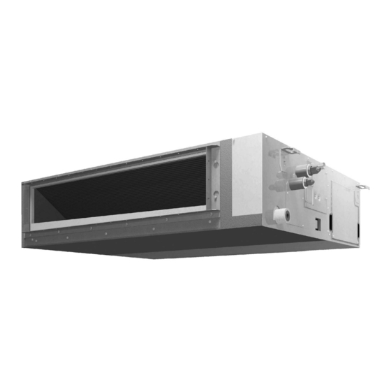
Ceiling-mounted Duct type
FXSQ05TAVJU
FXSQ15TAVJU
FXSQ07TAVJU
FXSQ18TAVJU
FXSQ09TAVJU
FXSQ24TAVJU
FXSQ12TAVJU
FXSQ30TAVJU
CAREFULLY READ THESE INSTRUCTIONS BEFORE INSTALLATION.
KEEP THIS MANUAL IN A HANDY PLACE FOR FUTURE REFERENCE.
INSTALLATION MANUAL
FXSQ36TAVJU
FXSQ48TAVJU
FXSQ54TAVJU
English
Français
Español
Advertisement
Table of Contents

Related Manuals for Daikin FXSQ05TAVJU


Summary of Contents for Daikin FXSQ05TAVJU
- Page 1 INSTALLATION MANUAL SYSTEM Inverter Air Conditioners MODELS Ceiling-mounted Duct type FXSQ05TAVJU FXSQ15TAVJU FXSQ36TAVJU FXSQ07TAVJU FXSQ18TAVJU FXSQ48TAVJU English FXSQ09TAVJU FXSQ24TAVJU FXSQ54TAVJU FXSQ12TAVJU FXSQ30TAVJU Français CAREFULLY READ THESE INSTRUCTIONS BEFORE INSTALLATION. KEEP THIS MANUAL IN A HANDY PLACE FOR FUTURE REFERENCE. Español...
-
Page 2: Table Of Contents
FXSQ05TAVJU FXSQ15TAVJU FXSQ36TAVJU VRV SYSTEM FXSQ07TAVJU FXSQ18TAVJU FXSQ48TAVJU Inverter Installation manual FXSQ09TAVJU FXSQ24TAVJU FXSQ54TAVJU Air Conditioners FXSQ12TAVJU FXSQ30TAVJU CONTENTS DANGER • Refrigerant gas is heavier than air and replaces oxygen. 1. SAFETY CONSIDERATIONS ........1 A massive leak can lead to oxygen depletion, especially 2. - Page 3 Corroding copper pipes or soldered parts may result in specified by Daikin are used, fire or explosion may occur. refrigerant leakage. (c) Near machinery emitting electromagnetic waves. Electromagnetic waves may disturb the operation of CAUTION the control system and cause the unit to malfunction.
-
Page 4: Before Installation
2. BEFORE INSTALLATION (10) Wire sealing (11) Washer for Name (9) Washer clamp material hanger When unpacking the indoor unit or moving the unit after unpacked, hold the hangers (4 places) and do not apply Quantity 4 pcs. 2 sheets 8 pcs. -
Page 5: Selection Of Installation Location
Points of the operation explanation Check Items to be checked In case of defective column In addition to the general usage, since the items in the Are the sizes of electric operation manual with the WARNING and Does not operate · wiring according to the burnout CAUTION marks are likely to result in human bodily... -
Page 6: Preparation Before Installation
4. PREPARATION BEFORE INSTALLATION [ Required installation space [in. (mm)] ] Figures indicate the minimum required installation space. (1) Check the relation of location between the ceiling opening and the indoor unit hanging bolts. (unit [in. (mm)]) • Provide one of the following service spaces for the maintenance and inspection of the control box and drain pump or for other services. - Page 7 • Ceiling framework reinforcement may be required in Control box order to keep the ceiling horizontal and prevent ceiling vibration after opening the ceiling holes. For details, consult your building and upholstery work contractors. Ceiling (5) Install the hanging bolts. • Use either a M8-M10 size bolt or equivalent.
-
Page 8: Installation Of Indoor Unit
<05-48 type> [ Washer fixing ] Suction flange Upper nut Washer clamp (9) (accessory) Washer for Insert hanger (11) (accessory) Replacement Chamber cover Fig. 7 <54 type> • Keep the air outlet covered with a protective sheet to pre- Suction flange vent weld spatter and other foreign materials from entering the indoor unit and damaging the resin drain pan. -
Page 9: Refrigerant Piping Work
6. REFRIGERANT PIPING WORK Table 2 Piping Tightening Dimension for • For the outdoor unit refrigerant piping, refer to the installa- Flare shape size torque processing flare [in. (mm)] tion manual attached to the outdoor unit. [in. (mm)] [lbf·ft. (N·m)] A [in. - Page 10 • After leak test, referring to Fig. 11, insulate both the • Before brazing refrigerant piping, have nitrogen flow gas and liquid piping connection with the attached joint through the refrigerant piping and substitute air with nitrogen (NOTE 1) (Refer to Fig. 12). Then, carry out insulating material (4) and (5) to prevent the pipings from getting exposed.
-
Page 11: Drain Piping Work
7. DRAIN PIPING WORK • Wrap the vinyl tape around the end of the metal clamp (1) so that the sealing material (Large) (6) to be used at (1) Carry out drain piping. the next process may not be damaged with the clamp Carry out drain piping so that drainage is ensured. - Page 12 < Caution to be taken when carrying out upward CAUTION drain piping (Refer to Fig. 16) > • To avoid the attached drain hose (2) getting excessive • The maximum height of the drain riser is 26-9/16 in. force, do not bend nor twist it. (675 mm).
- Page 13 (2) After piping is finished, check if the drain flows • Do not apply external force to the float switch. (It smoothly. may result in malfunction) • Do not touch the drain pump. [When the electric wiring work is finished] Touching the drain pump may cause electric • Gradually pour 1/4 gal. (1 ) of water from the inspec- shocks.
-
Page 14: Duct Work
8. DUCT WORK 9. ELECTRIC WIRING WORK Pay the utmost attention to the following items and con- 9-1 GENERAL INSTRUCTIONS duct the ductwork. • Make certain that all electric wiring work is carried out by • Check that the duct is not in excess of the setting range of qualified personnel according to the applicable legislation external static pressure for the unit. - Page 15 CAUTION FOR WIRING Voltage Model Hz Volts MCA MOP range • For connection to the terminal block, use ring type crimp style terminals with insulation sleeve or insulate the wirings FXSQ05TAVJU 0.078 properly. FXSQ07TAVJU 0.078 Wiring Insulation sleeve FXSQ09TAVJU 0.078 FXSQ12TAVJU 0.078...
- Page 16 WARNING Hook Conduit mounting • When wiring, form the wirings orderly so that the control plate (12) box lid can be securely fastened. If the control box lid is not Screws in place, the wirings may come out or be sandwiched by the (2 points) box and the lid and cause electric shocks or a fire.
- Page 17 (5) Mount the control box lid and wrap the wire sealing < No. 2 system: When carrying out group control or 2 material (small) (10) so that the wiring through hole remote controller control. > will be covered by the sealing material. Power supply Power supply Power supply...
-
Page 18: Field Setting
9-6 FOR CONTROL WITH 2 REMOTE CONTROL- 9-8 FOR REMOTE CONTROL (FORCE OFF OR ON / LERS (TO CONTROL 1 INDOOR UNIT WITH 2 OFF OPERATION) REMOTE CONTROLLERS) (1) Wiring method and specification • Remote control is available by connecting the external • For control with 2 remote controllers, set one remote con- input to the terminal T1 and T2 on the terminal block for troller as Main and the other remote controller as Sub. - Page 19 10-1 Settings for external static pressure CAUTION • Make settings in either method (a) or method (b). • If airflow pathway changes, such as duct and air outlet (a) Make settings with Air volume automatic adjust- changes, are made after air volume adjustments, be sure to ment function.
-
Page 20: Test Operation
11. TEST OPERATION Table 9 Mode FIRST SECOND • After cleaning the indoor unit inside, carry out test operation Setting CODE No. CODE No. according to installation manual attached to the outdoor Fan speed during unit. (Extra low) cooling 12 (22) • When the remote controller operation lamp flashes, it thermostat OFF Setting... - Page 21 5151 San Felipe, Suite 500 Houston, TX 77056 3P184443-13Z EM17A015A [1804] HT...
Need help?
Do you have a question about the FXSQ05TAVJU and is the answer not in the manual?
Questions and answers