Table of Contents
Advertisement
Quick Links
Advertisement
Table of Contents

Subscribe to Our Youtube Channel
Related Manuals for Mercury 25 Jet FourStroke


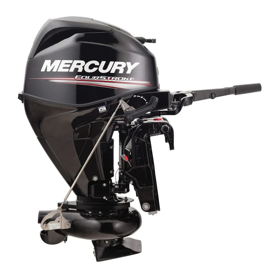
Summary of Contents for Mercury 25 Jet FourStroke
- Page 1 Operation Maintenance Installation Manual...
- Page 3 Thank you for purchasing one of our products. We sincerely hope your boating will be pleasant! Mercury Marine, Fond du Lac, Wisconsin, U.S.A. Name / function: John Pfeifer, President, Mercury Marine...
- Page 4 Warranty Message The product you have purchased comes with a limited warranty from Mercury Marine; the terms of the warranty are set forth in the Warranty Manual included with the product. The Warranty Manual contains a description of what is...
- Page 5 Copyright and Trademark Information © MERCURY MARINE. All rights reserved. Reproduction in whole or in part without permission is prohibited. Alpha, Axius, Bravo One, Bravo Two, Bravo Three, GO BOLDLY., Circle M with Waves Logo, K‑planes, Mariner, MerCathode, MerCruiser, Mercury, Mercury...
-
Page 7: Table Of Contents
Low Permeation Fuel Hose Requirement ............19 EPA Pressurized Portable Fuel Tank Requirements........19 Fuel Demand Valve (FDV) Requirement............19 Mercury Marine's Pressurized Portable Fuel Tank........... 20 Filling Fuel Tank....................21 Engine Oil Recommendations................21 Checking and Adding Engine Oil..............22 Features and Controls Remote Control Features................. - Page 8 Operation Prestarting Check List..................36 Operating in Freezing Temperatures..............36 Operating in Saltwater or Polluted Water............36 Operating in Shallow Water................37 How the Jet Drive Operates................37 Stopping the Boat in an Emergency..............39 Steering the Boat....................39 Mooring the Boat....................40 Water Intake Blockage..................
- Page 9 Storage Storage Preparation..................72 Protecting External Outboard Components............72 Protecting Internal Engine Components............73 Jet Drive......................73 Positioning Outboard for Storage..............73 Battery Storage....................73 Troubleshooting Starter Motor will not Crank the Engine (Electric Start Models)......74 Engine Will Not Start..................74 Engine Runs Erratically..................
- Page 10 viii...
-
Page 11: General Information
GENERAL INFORMATION Boater's Responsibilities The operator (driver) is responsible for the correct and safe operation of the boat and the safety of its occupants and general public. It is strongly recommended that each operator read and understand this entire manual before operating the outboard. -
Page 12: High-Speed And High-Performance Boat Operation
For additional information, obtain a copy of our Hi‑Performance Boat Operation booklet from your dealer, distributor, or Mercury Marine. Outboard Remote Control Models The remote control connected to your outboard must be equipped with a start in neutral only protection device. -
Page 13: Remote Steering Notice
GENERAL INFORMATION Remote Steering Notice The steering link rod that connects the steering cable to the engine must be fastened utilizing self‑locking nuts. These self‑locking nuts must never be replaced with nonlocking nuts. Nonlocking nuts may loosen and vibrate off, allowing the link rod to disengage. - Page 14 GENERAL INFORMATION The lanyard cord is usually 122–152 cm (4–5 feet) in length when stretched out, with an element on one end made to be inserted into the switch and a clip on the other end for attaching to the operator's PFD or wrist. The lanyard is coiled to make its at‑rest condition as short as possible to minimize the likelihood of lanyard entanglement with nearby objects.
- Page 15 GENERAL INFORMATION While activation of the lanyard stop switch will stop the engine immediately, a boat will continue to coast for some distance depending upon the velocity and degree of any turn at shut down. However, the boat will not complete a full circle.
-
Page 16: Protecting People In The Water
GENERAL INFORMATION Protecting People in the Water WHILE YOU ARE CRUISING It is very difficult for a person standing or floating in the water to take quick action to avoid a boat heading in his/her direction, even at slow speed. 21604 Always slow down and exercise extreme caution when boating in an area where there might be people in the water. -
Page 17: Wave And Wake Jumping
GENERAL INFORMATION Wave and Wake Jumping Operating recreational boats over waves and wake is a natural part of boating. However, when this activity is done with sufficient speed to force the boat hull partially or completely out of the water, certain hazards arise, particularly when the boat enters the water. -
Page 18: Exhaust Emissions
GENERAL INFORMATION WARNING Failure to correctly fasten the outboard could result in the outboard propelling off the boat transom resulting in property damage, serious injury, or death. Before operation, the outboard must be correctly installed with the required mounting hardware. If an obstacle is struck at planing speed and the outboard is not securely fastened to the transom, it is possible the outboard could lift off the transom and land in the boat. - Page 19 GENERAL INFORMATION Engine exhaust gases contain harmful carbon monoxide. Avoid areas of concentrated engine exhaust gases. When engines are running, keep swimmers away from the boat, and do not sit, lie, or stand on swim platforms or boarding ladders. While underway, do not allow passengers to be positioned immediately behind the boat (platform dragging, teak/body surfing).
-
Page 20: Selecting Accessories For Your Outboard
Some accessories not manufactured or sold by Mercury Marine are not designed to be safely used with your outboard or outboard operating system. Acquire and read the installation, operation and maintenance manuals for all your selected accessories. - Page 21 (refer to your boat's capacity plate). Know your boat's operating and loading limitations. Know if your boat will float if it is full of water. When in doubt, contact your authorized Mercury Marine dealer or the boat manufacturer. Ensure that everyone in the boat is properly seated.
- Page 22 GENERAL INFORMATION • Do not allow anyone to sit or ride on any part of the boat that was not intended for such use. This includes the backs of seats, gunwales, transom, bow, decks, raised fishing seats, and any rotating fishing seat. Passengers should not sit or ride anywhere that sudden unexpected acceleration, sudden stopping, unexpected loss of boat control, or sudden boat movement could cause a person to be thrown overboard or into the...
-
Page 23: Recording Serial Number
GENERAL INFORMATION Recording Serial Number It is important to record this number for future reference. The serial number is located on the outboard as shown. Model Number XXXXXXX Serial Number XXXXX XX XXXX XXX Me rc ury Marine Brunswick Corp. Made in Japan 24800 Serial number... -
Page 24: Specifications
GENERAL INFORMATION Examples: • XX = 2000 • HK = 2089 • AG = 2017 Specifications Models Power 18.4 kw (25 hp) Full throttle RPM range 5000–5500 RPM Idle speed in forward gear 850 ± 25 RPM Number of cylinders Piston displacement 526 cc (32.09 cid) Cylinder bore... -
Page 25: Component Identification
GENERAL INFORMATION Component Identification TILLER HANDLE/GAS ASSIST MODEL 24805 Top cowl Manual start handle Engine stop switch Throttle friction adjustment knob Gear shift Tilt support lever Gas tilt assist lever Jet drive housing Water intake housing Reverse gate Water outlet housing Chaps Water pump indicator hole Cowl latch... - Page 26 GENERAL INFORMATION Electric start button (electric start models) Lanyard stop switch Steering friction adjustment lever POWER TRIM/REMOTE CONTROL MODEL 24827 Transom brackets Tilt support lever Top cowl Cowl latch Bottom cowl Auxiliary tilt switch Chaps Water outlet housing Reverse gate Water intake housing Jet drive housing...
-
Page 27: Transporting
TRANSPORTING Trailering Boat/Outboard The boat should be trailered with the outboard tilted down in a vertical operating position. IMPORTANT: Do not rely on the power trim/tilt system or tilt support lever to maintain proper ground clearance for trailering. The outboard tilt support lever is not intended to support the outboard for trailering. -
Page 28: Fuel And Oil
USA is alcohol (ethanol, methanol, or butanol). GASOLINE CONTAINING ALCOHOL Bu16 Butanol Fuel Blends Fuel blends of up to 16.1% butanol (Bu16) that meet the published Mercury Marine fuel rating requirements are an acceptable substitute for unleaded gasoline. Contact your boat manufacturer for specific recommendations on your boat's fuel system components (fuel tanks, fuel lines, and fittings). -
Page 29: Low Permeation Fuel Hose Requirement
IMPORTANT: When operating a Mercury Marine engine on gasoline containing methanol or ethanol, do not store the gasoline in the fuel tank for long periods. Cars normally consume these blended fuels before they can absorb enough moisture to cause trouble;... -
Page 30: Mercury Marine's Pressurized Portable Fuel Tank
Vent/water drain holes 46453 Mercury Marine's Pressurized Portable Fuel Tank Mercury Marine has created a new portable pressurized fuel tank that meets the preceding EPA requirements. These fuel tanks are available as an accessory or are provided with certain portable outboard models. -
Page 31: Filling Fuel Tank
Mercury or Quicksilver NMMA FC‑W certified SAE 10W‑30 4‑Stroke Marine Engine Oil is recommended for general, all‑temperature use. If NMMA certified synthetic blend oil is preferred, use Mercury or Quicksilver SAE 25W‑40 Synthetic Blend Marine 4‑Stroke Engine Oil. If the recommended Mercury or Quicksilver NMMA FC‑W certified outboard oils are not available, a major... -
Page 32: Checking And Adding Engine Oil
FUEL AND OIL IMPORTANT: The use of nondetergent oils, multi‑viscosity oils (other than Mercury or Quicksilver NMMA FC‑W certified oil or a major brand NMMA FC‑W certified oil), synthetic oils, low quality or oils that contain solid additives are not recommended. - Page 33 Outboard engines can typically handle large amounts of oil dilution without causing durability problems. However, to ensure extended life of the outboard engine, Mercury recommends that the oil and filter be changed regularly following the oil change interval and using the recommended oil quality.
-
Page 34: Features And Controls
FEATURES AND CONTROLS Remote Control Features Your boat may be equipped with one of the Mercury Precision or Quicksilver remote controls shown. If not, consult your dealer for a description of the functions and operations of the remote control. 26800 Control handle –... - Page 35 FEATURES AND CONTROLS WARNING Insufficient friction adjustment can cause serious injury or death due to loss of boat control. When setting the friction adjustment, maintain sufficient steering friction to prevent the outboard from steering into a full turn if the tiller handle or steering wheel is released.
- Page 36 FEATURES AND CONTROLS • Tiller handle ‑ The tiller handle can be tilted 180° for convenient handling during transportation and storage. 28535 • Tiller lock release lever ‑ Push the lever to move the tiller handle from one position to another. Tilt lock release lever 3274...
- Page 37 FEATURES AND CONTROLS • Tiller handle lock cap ‑ Remove the lock cap on top of the tiller handle to lock in the up position. Push the tiller lock release lever to release the handle from the locked up position. 3273 Lock cap Locking mechanism...
- Page 38 FEATURES AND CONTROLS • Lanyard stop switch ‑ Refer to General Information ‑ Lanyard Stop Switch. 19791 BASIC TILTING OPERATION Models equipped with a gas assisted tilt system allows the operator to lock the outboard at any tilt position from full down to full up. This tilt system is designed to be adjusted when the outboard is idling in neutral, or with the engine turned off.
- Page 39 FEATURES AND CONTROLS TILTING OUTBOARD TO FULL UP POSITION 1. Stop the engine. Move the lock lever to the free position. Take hold of the top cowl grip and raise the outboard to the full tilt up position. Lock the outboard in place by moving the lock lever to the lock position.
-
Page 40: Power Trim And Tilt (If Equipped)
FEATURES AND CONTROLS Adjust the operating angle of the outboard so that the outboard runs perpendicular to the water when the boat is at full speed. Arrange passengers and load in the boat so the weight is distributed evenly. NOTE: The outboard should be locked against the tilt pin during operation by setting the tilt lock lever to the lock position. - Page 41 FEATURES AND CONTROLS POWER TRIM OPERATION The power trim and tilt feature of the outboard is convenient for drifting and when operating at low throttle speed in very shallow water. When under power, do not trim out the outboard in an effort to gain speed as is done with a conventional propeller driven boat.
-
Page 42: Warning System
FEATURES AND CONTROLS Turn out the manual tilt release valve three turns counterclockwise. This allows manual tilting of the outboard. Tilt the outboard to the desired position and tighten the manual tilt release valve. 9976 AUXILIARY TILT SWITCH The auxiliary tilt switch can be used to tilt the outboard up or down using the power trim system. - Page 43 FEATURES AND CONTROLS WARNING LIGHT The warning light will turn on or flash to alert the operator to the warning system situations listed in the following chart. 15732 WARNING SYSTEM OPERATION The warning horn will emit either a continuous beep or intermittent short beeps and engine speed will be limited.
- Page 44 FEATURES AND CONTROLS ENGINE OVERHEAT If the engine overheats, immediately reduce throttle speed to idle. Shift the outboard into neutral and check for a steady stream of water coming out of the water pump indicator hole. 9647 If no water is coming out of the water pump indicator hole, or flow is intermittent;...
-
Page 45: Replaceable Jet Drive Shear Key
FEATURES AND CONTROLS When the engine overspeed limiter is activated, it will reduce ignition voltage to momentarily decrease the engine speed. Excessive overspeed (above 6300 RPM) results in cutout of the cylinders to prevent operation above this limit. Replaceable Jet Drive Shear Key The jet drive is equipped with a shear key to protect it in the event of a lodged impeller. -
Page 46: Operation
(except in freezing temperatures) when not in use. Wash down the outboard exterior and flush out the exhaust outlet of the jet drive with fresh water after each use. Each month, spray Mercury Precision or Quicksilver Corrosion Guard on external metal surfaces. -
Page 47: Operating In Shallow Water
OPERATION Operating in Shallow Water The life of the impeller and water intake can be greatly increased by avoiding the intake of sand and gravel. The intake suction will act like a dredge when the water intake comes close to the bottom. It is better to stop the engine and drift up to shore when landing, and to shove off with an oar when leaving. - Page 48 OPERATION The driveshaft driven impeller draws water up through the water intake and then directs it at a high pressure through the water outlet nozzle to create forward thrust. To obtain reverse, the reverse gate moves over the outlet nozzle to direct the water in the opposite direction. 29022 Water intake Water outlet nozzle...
-
Page 49: Stopping The Boat In An Emergency
OPERATION Stopping the Boat in an Emergency A jet powered boat has emergency stopping capability unique to this form of propulsion. WARNING Using the emergency stopping capability of a jet drive unit will slow down the boat in an emergency. However, sudden stopping may cause the occupants of the boat to be thrown forward or out of the boat resulting in serious injury or death. -
Page 50: Mooring The Boat
OPERATION Mooring the Boat Be sure to tilt the jet drive out of the water when the boat is pulled onto a beach or tied to a dock in shallow water. Failure to do this may cause the water intake housing to fill with sand or debris and could prevent the outboard from cranking over for starting. -
Page 51: Prestarting Instructions
OPERATION Prestarting Instructions 1. Connect the remote fuel line to the outboard. Ensure the connector is snapped into place. 9600 2. Check the engine oil level. 9601 3. Ensure the driveshaft bearing on the jet drive is lubricated. Refer to Maintenance ‑... -
Page 52: Engine Break-In Procedure
OPERATION 4. Tiller handle models with manual or electric start, have a quick reference decal on the tiller handle that shows the sequence for starting the engine. 52396 Tiller handle starting sequence decal Engine Break‑in Procedure IMPORTANT: Failure to follow the engine break‑in procedures can result in poor performance throughout the life of the engine and can cause engine damage. - Page 53 OPERATION 2. Squeeze the fuel line primer bulb several times until it feels firm. 19779 IMPORTANT: To prevent engine flooding, do not squeeze the primer bulb after engine has warmed up. 3. Set the lanyard stop switch to the RUN position. Refer to General Information ‑...
-
Page 54: Starting The Engine - Tiller Handle Models
OPERATION 7. After the engine starts, check for a steady stream of water flowing out of the water pump indicator hole. 9647 IMPORTANT: If no water is coming out of the water pump indicator hole, stop the engine and check cooling water intake for obstruction. No obstruction may indicate a water pump failure or blockage in the cooling system. - Page 55 OPERATION 3. Set the lanyard stop switch to the RUN position. Refer to General Information ‑ Lanyard Stop Switch. 19791 4. Set the tiller handle grip to the neutral start position. START 24834 5. Set the gear shift to the neutral N position. 24835 6.
- Page 56 OPERATION 7. Manual starting models ‑ Pull the starter rope slowly until the starter engages, then pull rapidly to crank the engine. Allow the rope to return slowly. Repeat until the engine starts. 10173 8. Electric starting models ‑ Push the starter button and crank the engine. Release the button when the engine starts.
-
Page 57: Gear Shifting
OPERATION Gear Shifting NOTE: The propeller continues to rotate while the engine is in neutral. Although the approximate balancing of forward and reverse thrust will minimize boat movement, the boat may tend to move slowly forward and backward. This is normal for a direct‑drive jet driven boat. -
Page 58: Stopping The Engine
OPERATION Stopping the Engine Reduce the engine speed and shift the outboard to neutral position. Push in the stop switch or move the lanyard stop switch to the "OFF" position. 26776 Emergency Starting If the starter system fails, the engine can be started using the spare starter rope (provided). - Page 59 OPERATION WARNING The neutral‑speed‑protection device is inoperative when starting the engine with the emergency starter rope. Set the engine speed at idle and the gear shift in neutral to prevent the outboard from starting in gear. 3. Electric start models ‑ Turn the ignition key to the "ON" position. 26846 WARNING High voltage is present any time the key is turned on, especially when...
-
Page 60: Maintenance
Record maintenance performed in the Maintenance Log at the back of this book. Save all maintenance work orders and receipts. Selecting Replacement Parts For Your Outboard We recommend using original Mercury Precision or Quicksilver replacement parts and Genuine Lubricants. DO NOT USE CAUSTIC CLEANING CHEMICALS IMPORTANT: Do not use caustic cleaning chemicals on the outboard power package. - Page 61 Keep water spray out of the air filter/intake and alternator. After washing, allow the powerhead and components to dry. Apply Quicksilver or Mercury Precision Lubricants Corrosion Guard spray on the external metal surfaces of the powerhead and powerhead components. Do not allow the Corrosion Guard spray to come in contact with the alternator drive belt or belt pulleys.
-
Page 62: Epa Emission Regulations
EPA Emission Regulations All new outboards manufactured by Mercury Marine are certified to the United States Environmental Protection Agency, as conforming to the requirements of the regulations for the control of air pollution from new outboard motors. This certification is contingent on certain adjustments set to factory standards. -
Page 63: Inspection And Maintenance Schedule
MAINTENANCE The owner/operator is not to modify the engine in any manner that would alter the horsepower or allow emission levels to exceed their predetermined factory specifications. Inspection and Maintenance Schedule DAILY CHECKS • Check the engine oil level • Check the lanyard stop switch •... -
Page 64: Top Cowl Removal And Installation
MAINTENANCE • Check the remote control cable adjustment, if equipped—dealer item • Replace the high‑pressure fuel filter, if equipped—dealer item • Replace the accessory drive belt, if equipped—dealer item • Check the power trim fluid level, if equipped—dealer item • Inspect the engine motor mounts—dealer item Top Cowl Removal and Installation REMOVAL... -
Page 65: Impeller Clearance Adjustment
MAINTENANCE • Difficulty getting the boat on plane • An increase in engine RPM at wide‑open throttle IMPORTANT: Do not sharpen or alter the top side lifting angle. Check the impeller blades occasionally for damage. Use a flat file to sharpen the leading edges. -
Page 66: Impeller Removal And Installation
MAINTENANCE Impeller Removal and Installation WARNING Rotating the driveshaft may cause the engine to crank over and start. To prevent this type of accidental engine starting and possible serious injury caused from being struck by a rotating impeller, always turn the ignition key or lanyard stop switch to the "OFF"... - Page 67 MAINTENANCE 5. Straighten the bent tabs on the impeller nut retainer and remove the impeller nut. Tabs Impeller nut 29082 6. Pull the impeller straight off the shaft. If the impeller is tight, use a hammer and a block of wood to rotate the impeller clockwise on the shaft until the keyway is directly above the flat on the shaft.
- Page 68 MAINTENANCE 4. Temporarily install the water intake housing in order to check for impeller clearance. The clearance between the impeller and liner should be 0.8 mm (0.03 in.). Shim washers can be transferred to either side of the impeller to raise or lower the impeller to the correct clearance setting. The water intake housing can be shifted sideways a small amount in order to center the liner.
-
Page 69: Shift Link Rod Adjustment
MAINTENANCE 6. Install the water intake housing with six bolts. Check clearance around the impeller to ensure the water intake housing is centered and not rubbing against the liner. Tighten the mounting bolts to the specified torque. 29081 Description lb‑in. lb‑ft Water intake housing mounting bolts 13.5... -
Page 70: Battery Inspection
MAINTENANCE 2. Adjust the length of the shift link rod so the roller is at the full end of travel (bottom) in the shift cam when the shift handle is in forward. Battery Inspection The battery should be inspected at periodic intervals to ensure proper engine starting capability. -
Page 71: Steering Link Rod Fasteners
MAINTENANCE 2. Loosen the hex nut and remove the filter assembly from the mount. Hold on to the cover to prevent it from turning and remove the sight bowl. Empty the contents into an approved container. 3. Inspect the filter element. If replacement is necessary, replace the filter assembly. -
Page 72: Corrosion Control Anode
MAINTENANCE Assemble steering link rod to steering cable with flat washer and nylon insert locknut. Tighten locknut until it seats, then back nut off 1/4 turn. Assemble steering link rod to engine with bolt, locknut, spacer, and flat washers. Tighten the locknut to the specified torque. 9691 Bolt (10‑898101018) Flat washer (12‑95392‑10) -
Page 73: Spark Plug Inspection And Replacement
MAINTENANCE One anode is installed in the engine block. Remove the flange screw at the location shown. Remove the screw securing the anode. Fasten the anode to the flange screw. Tighten the screw to the specified torque. Install the flange screw with a new O‑ring. -
Page 74: Fuse Replacement - Electric Start Models
MAINTENANCE 1. Remove the spark plug leads. Twist the rubber boots slightly and pull off. 26899 2. Remove the spark plugs to inspect. Replace spark plug if electrode is worn or the insulator is rough, cracked, broken, blistered, or fouled. 26946 3. -
Page 75: Timing Belt Inspection
MAINTENANCE Open the fuse holder and look at the silver colored band inside the fuse. If band is broken, replace the fuse. Replace fuse with a new fuse with the same rating. 15917 Good fuse Blown fuse Timing Belt Inspection Inspect the timing belt and have it replaced by an authorized dealer if any of the following conditions are found. - Page 76 MAINTENANCE Tube Ref Description Where Used Part No. Extreme Grease Driveshaft bearing 8M0071842 2-4-C with PTFE Driveshaft bearing 92-802859A 1 • Driveshaft bearing IMPORTANT: It is important not to use a general all‑purpose grease for this bearing. The lubricant recommended is a water‑resistant grease of the proper consistency for this application.
- Page 77 MAINTENANCE • Swivel bracket ‑ Lubricate through fitting. 24839 • Tilt tube ‑ Lubricate through fittings. 15915 • Lubricate the threads on the transom clamp screws (if equipped). 15914...
-
Page 78: Checking Power Trim Fluid
MAINTENANCE • Steering cable grease fitting (if equipped) ‑ Rotate the steering wheel to fully retract the steering cable end into the outboard tilt tube. Lubricate through fitting. 59492 Fitting Steering cable end WARNING Incorrect cable lubrication can cause hydraulic lock, leading to serious injury or death from loss of boat control. -
Page 79: Changing Engine Oil
MAINTENANCE 2. Remove the fill cap and check the fluid level. The fluid level should be even with the bottom of the fill hole. Add Quicksilver or Mercury Precision Lubricants Power Trim and Steering Fluid. If not available, use automotive (ATF) automatic transmission fluid. - Page 80 MAINTENANCE 2. Turn the steering on the outboard so that the drain hole is facing downward. Remove the drain plug and drain the engine oil into an appropriate container. Lubricate the seal on the drain plug with oil and install. 24854 Drain plug CHANGING OIL FILTER...
-
Page 81: Submerged Outboard
MAINTENANCE 2. Idle the engine for five minutes and check for leaks. Stop the engine and check oil level on the dipstick. Add oil if necessary. Oil fill cap 9737 Submerged Outboard A submerged outboard will require service within a few hours by an authorized dealer once the outboard is recovered from the water. -
Page 82: Storage Preparation
STORAGE Storage Preparation The major consideration in preparing your outboard for storage is to protect it from rust, corrosion, and damage caused by freezing of trapped water. The following storage procedures should be followed to prepare your outboard for out‑of‑season storage or prolonged storage (two months or longer). NOTICE Without sufficient cooling water, the engine, the water pump, and other components will overheat and suffer damage. -
Page 83: Protecting Internal Engine Components
STORAGE • Spray Quicksilver or Mercury Precision Lubricants Corrosion Guard on external metal surfaces (except corrosion control anodes). Tube Ref Description Where Used Part No. Corrosion Guard External metal surfaces 92-802878 55 Protecting Internal Engine Components • Remove the spark plugs and inject a small amount of engine oil inside of each cylinder. -
Page 84: Troubleshooting
TROUBLESHOOTING Starter Motor will not Crank the Engine (Electric Start Models) POSSIBLE CAUSES • Blown fuse in the starting circuit. Refer to Maintenance section. • Outboard is not shifted to neutral position. • Weak battery or battery connections are loose or corroded. •... -
Page 85: Engine Overspeed (Excessive Rpm)
TROUBLESHOOTING • Incorrect setup and adjustments. • Fuel is being restricted to the engine. a. Engine fuel filter is obstructed. Refer to Maintenance section. b. Fuel tank filter obstructed. c. Stuck antisiphon valve located on permanently built‑in type fuel tanks. d. -
Page 86: Owner Service Assistance
STOLEN POWER PACKAGE If your power package is stolen, immediately advise the local authorities and Mercury Marine of the model and serial numbers and to whom the recovery is to be reported. This information is maintained in a database at Mercury Marine to aid authorities and dealers in the recovery of stolen power packages. - Page 87 RESOLVING A PROBLEM Satisfaction with your Mercury product is important to your dealer and to us. If you ever have a problem, question or concern about your power package, contact your dealer or any authorized Mercury dealership. If you need additional assistance: 1.
-
Page 88: Ordering Literature
Ordering Literature Before ordering literature, have the following information about your power package available: Model Serial Number Horsepower Year UNITED STATES AND CANADA For additional literature for your Mercury Marine power package, contact your nearest Mercury Marine dealer or contact:... - Page 89 (USA only) P.O. Box 1939 Fond du Lac, WI 54936-1939 OUTSIDE THE UNITED STATES AND CANADA Contact your nearest Mercury Marine authorized service center to order additional literature that is available for your particular power package. Mercury Marine Submit the following...
-
Page 90: Installation
INSTALLATION Installation Information MERCURY MARINE VALIDATED ENGINE MOUNTING HARDWARE IMPORTANT: Mercury Marine provides validated fasteners and installation instructions, including torque specifications, with all of our outboards so they can be properly secured to boat transoms. Improper installation of the outboard can cause performance and reliability issues that can lead to safety concerns. - Page 91 Some accessories not manufactured or sold by Mercury Marine are not designed to be safely used with your outboard or outboard operating system. Acquire and read the installation, operation and maintenance manuals for all your selected accessories.
-
Page 92: Top Cowl Removal And Installation
INSTALLATION ELECTRIC FUEL PUMP If an electric fuel pump is used, the fuel pressure must not exceed 27.58 kPa (4 psi) at the engine. If necessary, install a pressure regulator to regulate the pressure. Top Cowl Removal and Installation TOP COWL REMOVAL 1. -
Page 93: Lifting Outboard
INSTALLATION Lifting Outboard Use the lifting eye located aft of the flywheel to support the engine when installing the outboard. 10111 Determining the Mounting Height of the Outboard Jet The following outboard mounting height settings will work good for most applications, however, because of different boat/hull designs, the setting should be checked by test running the boat. - Page 94 INSTALLATION BOATS WITH A "V" BOTTOM HULL 1. Measure the width of the leading edge on the water intake housing. Make a horizontal line on the transom up from the "V" bottom the same length as the width of the water intake housing. 22401 Horizontal line Width of the leading edge on the water intake housing...
-
Page 95: Fastening The Outboard
INSTALLATION 2. Fasten outboard to the transom at this height. Refer to Fastening the Outboard. 22403 Fastening the Outboard WARNING Failure to correctly fasten the outboard could result in the outboard propelling off the boat transom resulting in property damage, serious injury, or death. Before operation, the outboard must be correctly installed with the required mounting hardware. - Page 96 INSTALLATION IMPORTANT: Determine the strength of the boat transom. The outboard mounting locknuts and bolts should be able to hold 75 Nm (55 lb‑ft) of torque without the boat transom yielding or cracking. If the boat transom yields or cracks under this torque, the construction of the transom may not be adequate. The boat transom must be strengthened or the load carrying area increased.
-
Page 97: Steering Bracket, Steering Cable Installation
INSTALLATION 4. Fasten the outboard with provided mounting hardware shown. Tighten the locknuts to the specified torque. The outboard must be secured to the transom with the two transom bracket clamp screws and four 13 mm (1/2 in.) diameter mounting bolts and locknuts provided. -
Page 98: Steering Link Rod Fasteners
INSTALLATION 4. Insert the steering cable into the tilt tube and secure with the steering cable nut. Tighten the steering cable nut to the specified torque. 59494 Steering cable nut Steering bracket bolt and washer (2) Steering cable seal Description lb‑in. - Page 99 INSTALLATION 1. Install the steering link rod onto the steering bracket aft threaded hole. 59496 2. Assemble the steering link rod onto the steering bracket with the bolt, two washers, spacer, and a locknut. Do not tighten the bolt or locknut at this time.
- Page 100 INSTALLATION 3. Install the loose end of the steering link onto the steering cable and secure with a washer and locknut. Tighten the locknut securely and then back the nut off 1/4 turn. Washer Locknut 59499 4. Tighten the link rod bolt to the specified torque. 5.
-
Page 101: Electrical Harness, Battery Connection, Fuel Tanks
INSTALLATION 6. Secure the battery cables to the throttle/shift cable with two cable ties to prevent contact with the steering components. 59502 Electrical Harness, Battery Connection, Fuel Tanks REMOTE WIRING HARNESS 1. Remove the three access cover bolts. Remove the access cover and cable rubber grommet. - Page 102 INSTALLATION 2. Remove the cable barrel retainer. Cable barrel retainer 24857 3. Loosen the harness retainer. Route the remote harness into the cowl as shown and below the harness retainer. 24858 Harness retainer Remote harness...
- Page 103 INSTALLATION 4. Connect the remote harness to the engine harness connector. 24859 Harness connector 5. Fasten the remote harness to the cowl with the harness retainer. Tighten the bolt to the specified torque. Description lb‑in. lb‑ft Harness retainer bolt – BATTERY CABLE CONNECTIONS IMPORTANT: To prevent damage to the engine charging system when the battery cables are not connected to a battery, ensure the battery cable ends...
-
Page 104: Control Cable Installation
INSTALLATION Dual Outboards Connect a common ground cable (wire size same as engine battery cables) between negative (–) terminals on starting batteries. 15497 Red sleeve ‑ positive (+) Black sleeve ‑ negative (–) Ground cable Cranking battery FUEL TANKS Portable Fuel Tank Select a suitable location in the boat within the engine fuel line length limitations and secure the tank in place. - Page 105 INSTALLATION 1. Move the remote control handle from neutral into forward and advance the handle to full speed position. NOTE: The throttle cable is the second cable to move when moving the control box out of neutral. 2. Install the throttle cable to the throttle actuating lever. Secure with a washer and cotter pin retainer.
- Page 106 INSTALLATION 6. Adjust the throttle cable barrel if the cam roller is touching the cam. 15952 Cam roller Throttle cam 7. Install the cable grommet. 8. Secure the throttle cable barrel with the cable barrel retainer. 9. Tighten the cable barrel retainer bolt to the specified torque. 24903 Cable barrel retainer Cable barrel retainer bolt...
- Page 107 INSTALLATION 10. Install the access cover and secure with three bolts. Tighten bolts to the specified torque. 15858 Description lb‑in. lb‑ft Access cover bolt (3) – SHIFT CABLE INSTALLATION WARNING If not properly installed, the reverse gate can interfere with water coming off the rudder, suddenly and unexpectedly slowing the boat.
-
Page 108: Water Testing
INSTALLATION 4. Attach the shift cable adjustment barrel to the bracket with a bolt and locknut. Tighten the bolt until it seats against the adjustment barrel, then back‑off the bolt 1/4 turn. Hold the bolt from turning, and tighten the locknut on the bolt. - Page 109 INSTALLATION IMPORTANT: If the angle of the boat transom does not allow the driveshaft housing to be positioned vertical, a wedge kit should be installed behind the transom brackets to increase the tilt‑in angle. NOTE: Slight cavitation in sharp turns and rough water is acceptable, but excessive cavitation is harmful to the outboard and should be avoided.
-
Page 110: Maintenance Log
MAINTENANCE LOG Maintenance Log Record all maintenance performed on your outboard here. Be sure to save all work orders and receipts. Date Maintenance Performed Engine Hours...
Need help?
Do you have a question about the 25 Jet FourStroke and is the answer not in the manual?
Questions and answers