Metro DataVac C5 Instructions For Use Manual
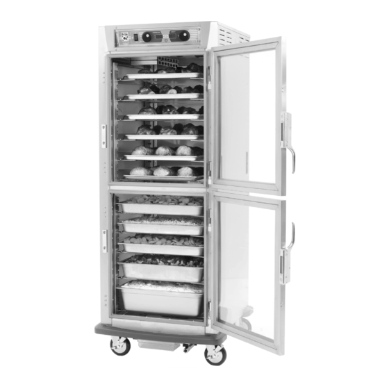
9 series controlled humidity heated holding & proofing cabinets
Hide thumbs
Also See for C5:
- Instructions for use manual (8 pages) ,
- Instructions for use manual (8 pages) ,
- Instructions for use manual (12 pages)
Table of Contents
Advertisement
InterMetro Industries Corporation
Wilkes-Barre, PA 18705
1-800-992-1776 www.metro.com
9 Series
Controlled
Humidity
Heated
Holding &
Proofing
Cabinets
INSTRUCTIONS
FOR USE
This manual covers cabinets with electrical ratings of:
120V 2000W, 120V 1440W & 220-240V 1681-2000W.
Hot Food Holding applications only
When ordering
electrical parts,
always confirm the
rating listed on rear
cabinet data plate.
Differences on voltage,
amps or wattage are
listed with bold text
in replacement part
descriptions.
Metro Heated Cabinets are for
L01-419
TM
Rev.I
10/11/17
Advertisement
Table of Contents

Related Manuals for Metro DataVac C5


Summary of Contents for Metro DataVac C5
- Page 1 9 Series Controlled Humidity Heated Holding & Proofing Cabinets INSTRUCTIONS FOR USE This manual covers cabinets with electrical ratings of: 120V 2000W, 120V 1440W & 220-240V 1681-2000W. When ordering electrical parts, always confirm the rating listed on rear cabinet data plate. Differences on voltage, amps or wattage are listed with bold text...
- Page 2 1. With the POWER switch OFF, plug the supply power cord into an appropriate, grounded, receptacle. (Refer to the cabinet data plate for voltage and ampere rating). 2. Fill the water reservoir in the floor of the cabinet with clean warm water. The capacity of the reservoir is about 4 U.S. Gallons (15 liters). The water level should be no higher than inch (13mm) below the bottom of the water reservoir cover. 3. Ensure that the water reservoir cover is installed (refer to the cabinet operating instructions). This is required for the cabinet to function properly. 4. Set the POWER switch to the ON position. 5. The cabinet will initially display current temperature and humidity set points and then show the actual cabinet temperature and humidity. 6. The temperature and humidity displays will continue to blink until the temperature set point is reached. 7. To change temperature or humidity set points, turn a control knob. As a knob is turned, the temperature and humidity display will show the set points, and the “F° and C°” indicator lamps will blink. About 3 seconds after a knob is turned, the display will show the actual cabinet temperature and humidity. 8. Press and release “Recall Set Points” button to see the current cabinet temperature and humidity set points. 9. To see the current alarm set point, press and release “Low Temp Alarm” button. To change the alarm set point, press and hold “Low Temp Alarm” button, turn the temperature knob to the desired setting, and release button. 10. To clean cabinet, turn power off, unplug from wall outlet, allow cabinet to cool, wipe with a damp cloth and dry with a towel. Floor of cabinet and water reservoir may be rinsed out with a low pressure hose. 11. Consult the instructions for use for additional operation and maintenance information.
-
Page 3: Table Of Contents
TABLE OF CONTENTS SECTION PAGE I. Quick Start Guide............(cover) II. Basic Operating Guidelines ....Inside Front Cover III. Safety Instructions ..............1 IV. Identifying Your Cabinet ............. 2 V. Installation & Set-up ............. 3 VI. Product Features ..............7 VII. Operating Instructions ............8 VIII. -
Page 4: Identifying Your Cabinet
Fill out and return the warranty card located at the back of this manual. PART NUMBERING C5 9 9 X - S FS - L P FS A CABINET NAME A = ACCESSORIES (IF APPLICABLE) CABINET TYPE... -
Page 5: Installation & Set-Up
(°C or °F) of temperature selected. Your C5 cabinet is designed to operate next to walls and other kitchen equipment. However, the greater the clearance around the sides and the top of the cabinet, the cooler the electrical components will operate. - Page 6 (includes slides and uprights) (includes slides and uprights) (includes slides and uprights) Slides sold in pairs. For additional pair of wire slides, order C5-USLIDEPR-C for Chrome or C5-USLIDEPR-S for Stainless Steel. To order individual universal uprights only, see item #’s 39A, 39B, 39C.
- Page 7 INSTALLATION AND SET-UP (continued) CORRECT ORIENTATION OF LIP LOADED SLIDE RACKS Full Height Full Height Height Height Under Counter Single Door Dutch Doors Cabinet Cabinet Cabinet 2-piece Construction 2-piece Construction 1-piece Construction 1-piece Construction 1-piece Construction Part No. RPC5-L9 Part No. RPC5-L9 Part No.
- Page 8 C5 doors are normally hinged on the right hand side at the factory. If the cabinet has been in operation, allow the door to cool before reversing the door hinging direction. Note: When finished, all holes will have screws in them and there will be no exposed holes left in the cabinet.
-
Page 9: Product Features
PRODUCT FEATURES Control Panel Tray Slides Field Reversible Doors Be careful when opening the doors as hot, humid air will escape the cabinet. Air Duct Flush Pull Handles Water Reservoir Water Drain Fill with water to Allow water to cool about one half before draining. -
Page 10: Operating Instructions
To insure food safety, the C5 cabinet uses Temperature Priority. This feature is designed to minimize the time required to pre-heat a cold cabinet to the desired operating temperature and to recover to the operating temperature after a door has been opened and closed. To do this, during pre-heat and recovery, all the available electrical energy is used to heat the cabinet. - Page 11 Your C5 9 Series cabinet is capable of creating high levels of humidity at all operating temperatures. As you operate the cabinet and open and close the door(s), condensation will form on the inside surfaces of the cabinet. Some dripping of water may occur to the outside of the cabinet particularly at the door seals. A drip trough is part of the bumper and will direct most of this water to a removable water pan under the bumper.
-
Page 12: Care & Maintenance
CARE & MAINTENANCE Cleaning The Cabinet Warning: Unplug the cabinet before cleaning or servicing. Do not wash the cabinet with a water jet or high pressure water. Caution: Do not spray or pour water into the control enclosure. To clean the cabinet, wipe with a damp cloth and dry with a towel. Use only cleaning agents approved for stainless steel or aluminum (depending on your cabinet construction). Caution: Do not use cleaners with chlorides or phosphates as they may cause damage to stainless steel. Do not use strong alkalis on aluminum as they may discolor it. Use cleaners in the proper concentrations. Follow the manufacturer’s directions for the cleaning product used. The floor of the cabinet and water reservoir may be hosed out with low pressure water. After using any cleaning products, thoroughly rinse all surfaces to remove all residue. -
Page 13: Basic Troubleshooting
BASIC TROUBLESHOOTING Warning: Only factory approved service agents should attempt to service, repair or replace electrical components, wiring or power cord. 1. Controls do not work (no display or indicator lights): a. Check that the cabinet is plugged in. b. Check that the outlet has power. c. Check that the power switch is in the “On” position. d. - Page 14 BASIC TROUBLESHOOTING (continued) Warning: Only factory approved service agents should attempt to service, repair or replace electrical components, wiring or power cord. 8. Humidity too low: a. Set point is too low. Turn humidity set point up to the desired humidity. b. Cabinet may be producing the maximum humidity capable at the current temperature setting and food moisture content.
-
Page 15: Service & Replacement Parts
SERVICE and REPLACEMENT PARTS C5 9 SERIES REPLACEMENT PARTS — ELECTRICAL Confirm the cabinet electrical rating before ordering components. Warning: Only factory approved service agents should attempt to service, repair or replace electrical components, wiring or power cord. To access the controller area, remove the (7) screws holding the cabinet top in place. Lift the rear portion of the cabinet top and slide it away from under the front control bezel, removing it from the cabinet. - Page 16 SERVICE and REPLACEMENT PARTS (continued) C5 9 SERIES REPLACEMENT PARTS — CABINET BODY ITEM # Replacement Part No. Description ITEM # Replacement Part No. Description B5DN 5" SWIVEL CASTER RPC06-873B FULL HEIGHT DOOR GASKET 3" SWIVEL CASTER RPC06-873C HEIGHT DOOR GASKET RPQC02-247 6"...
- Page 17 SERVICE and REPLACEMENT PARTS (continued) Replacement Parts Diagram AIR DUCT See page 13. STRAIGHT PLUG CORD SHOWN CABINET BODY CONTROL PANEL See page 15. RESERVOIR COVER 3", 5" or 6" 3", 5" or 6" WIRE COVER WATER RESERVOIR See page 16. *For slide identification, see pages 4 and 5.
- Page 18 SERVICE and REPLACEMENT PARTS (continued) Warning: Only factory approved service agents should attempt to service, repair or replace electrical components, wiring or power cord. INCLUDES ITEM # 14 INSULATION INCLUDES * For Selected ITEM # 28 Models Only ENCLOSURE * For Selected Models Only WATER RESERVOIR...
- Page 19 SERVICE and REPLACEMENT PARTS (continued) C5 9 Series Wiring Diagram Warning: Only factory approved service agents should attempt to service, repair or replace electrical components, wiring or power cord.
- Page 20 InterMetro Industries Corporation (hereinafter referred to as “Seller”) warrants to the 10/17...
-
Page 21: Warranty
Thank you for purchasing a Metro C5 Controlled Humidity Cabinet. We are certain you will be more than satisfied with its quality and performance. Please fill in the warranty information space below so we may register your warranty. Also, so that we may learn more about our customers and hopefully be of continued service in the future, please take a moment to fill in the customer information space below. Thank You CUT ALONG DOTTED LINE CUSTOMER INFORMATION WARRANTY INFORMATION: 1. Which one of the following best describes Cabinet Model No. your establishment? Cabinet Serial No. ❑ Full-Service Restaurant Date Purchased ❑ Banquet Hall Customer Name ❑ Hotel Motel Address ❑ Hospital Nursing Home ❑... - Page 22 STAPLE HERE...
- Page 23 THIS PAGE IS KEPT INTENTIONALLY BLANK...
- Page 24 InterMetro Industries Corporation North Washington Street, Wilkes-Barre, PA 18705 L01-419 Rev. I 10 For Product Information Call: 1-800-992-1776 Information and specifications are subject to change Visit Our Web Site: www.metro.com without notice. Please confirm at time of order.
Need help?
Do you have a question about the C5 and is the answer not in the manual?
Questions and answers