
Related Manuals for Hiwin D2


Summary of Contents for Hiwin D2
- Page 1 D2 Drive User Guide v1.8 D2 Drive User Guide Version 1.8 December 7, 2016 HIWIN Mikrosystem Corp.
-
Page 2: Table Of Contents
D2 Drive User Guide v1.8 Table of Contents Table of Contents About the User Guide ....................... 1 1.1. Instructions before use ................... 2 1.2. Safety instructions ....................4 Specifications ........................7 2.1. Drive information ....................8 2.1.1. Safety certification ..................8 2.1.2. - Page 3 D2 Drive User Guide v1.8 Table of Contents 4.6.1. System wiring diagram for pulse command..........65 4.6.2. System wiring diagram for voltage command ..........73 4.6.3. System wiring diagram for PWM command ..........75 Drive Configuration ......................79 5.1. Installation and communication ................80 5.1.1.
- Page 4 D2 Drive User Guide v1.8 Table of Contents 6.5.3. Mathematical operation ................162 6.6. Advanced gains ....................165 6.6.1. Filter ......................165 6.6.2. Acceleration feed-forward ................. 167 6.6.3. Schedule gains and velocity loop gain ............169 6.6.4. Analog input....................172 6.6.5.
- Page 5 D2 Drive User Guide v1.8 Table of Contents 8.5.2. Drive over temperature protection ............. 244 8.6. Over voltage protection ..................245 Troubleshooting ......................249 Drive’s status indicator ..................250 9.1. Drive’s errors and warnings ................251 9.2. 9.2.1. Status display area on Lightening HMI ............251 9.2.2.
- Page 6 (2) Update the description according to motor model. (1) Add the information for D2T drive. (2) Renew the dimension of D2 drive. (3) Add the dimension of D2 drive with EtherCAT (CoE/mega-ulink). (4) Remove the brake wiring without a relay.
-
Page 7: About The User Guide
D2 Drive User Guide v1.8 1. About the User Guide 1. About the User Guide About the User Guide ....................... 1 1.1. Instructions before use ................... 2 1.2. Safety instructions ....................4 HIWIN Mikrosystem Corp. -
Page 8: Instructions Before Use
1. About the User Guide 1.1. Instructions before use This document is suitable for D2-series drives, included D2 model and D2T model. Read the User Guide carefully before using the product. HIWIN Mikrosystem Corp. (“the Company”) will not take any responsibility for damages, accidents, or injuries caused by the installation or use that is not performed according to these instructions. - Page 9 D2 Drive User Guide v1.8 1. About the User Guide Risks specifically identified: Warning Warning At installing or exchanging motor power Each motor model has its own rated cables, correct sequence maximum payload. If applying more than connection is not followed, the motor may such payload to the motor, it may cause run abnormally.
-
Page 10: Safety Instructions
D2 Drive User Guide v1.8 1. About the User Guide 1.2. Safety instructions Read the User Guide carefully before the installation, transportation, maintenance, and inspection. Ensure that the product is used correctly. Users should read the EM information, safety information, and all related instructions before using the product. - Page 11 D2 Drive User Guide v1.8 1. About the User Guide Usage instructions Warning Do not touch the terminal or inside part when it is powered to avoid electric shock. Do not touch the terminal or inside within 10 minutes from the power off.
- Page 12 D2 Drive User Guide v1.8 1. About the User Guide Installation Attention Do not place any heavy objects on the product to avoid damage. Do not mix with debris to avoid fire. Ensure that the product is installed in the required direction to avoid fire.
-
Page 13: Specifications
D2 Drive User Guide v1.8 2. Specifications 2. Specifications Specifications ........................7 2.1. Drive information ....................8 2.1.1. Safety certification ..................8 2.1.2. Nameplate information .................. 8 2.1.3. Model number ....................9 2.2. Drive specifications ....................10 2.3. Drive dimensions ....................14 2.4. -
Page 14: Drive Information
D2 Drive User Guide v1.8 2. Specifications 2.1. Drive information 2.1.1. Safety certification The drive complies with the following safety regulations. CE Compliance Table 2-1 EN 61800-3: 2004 (Category C2) EN 61000-3-2: 2006/A1: 2009/A2: 2009 EN 61000-3-3: 2008 IEC CISPR 11: 2009/A1: 2010... -
Page 15: Model Number
(3) The frame D model requires the voltage range of 3-phase 220 Vac. (4) D2 model does not support the extension I/O module and the rated output of 2.0 KW. (5) D2T frame A, B, and C models do not have the Modbus module. -
Page 16: Drive Specifications
For the dual-loop model, the rotary encoder should be the Other 17-bit serial absolute encoder and the linear encoder should be the digital AqB encoder. 9 (general purpose) for D2 model Input 10 (general purpose) for D2T model Control signal... - Page 17 D2 Drive User Guide v1.8 2. Specifications Switchable control modes (1) Position control; (2) Velocity control; Control mode (3) Torque control ; (4) Position/velocity control; (5) Position/torque control ; (6) Velocity/torque control; (1) Inhibit pulse command; (2) Axis enable; (3) Switch between primary and secondary CG;...
- Page 18 D2 Drive User Guide v1.8 2. Specifications (1) Servo ready; (2) Errors; Control output (3) In-velocity; (4) Zero speed detected, etc. Torque commands can be provided by the duty cycle of Torque command PWM input PWM input. Parameters are used to set the scale and input command direction.
- Page 19 D2 Drive User Guide v1.8 2. Specifications Unit: um, count. Enable method: it is activated after the internal homing is completed, or by an external input signal. Frame A - C: need external connection (option), and have no built-in regenerative resistor.
-
Page 20: Drive Dimensions
Dimensions and mounting holes of D2-series drives, D2-series drives with the EtherCAT (CoE/ mega-ulink) module, and D2-series drives with the extension I/O module are shown in the following figures. The dimension unit is in mm, and the diameter of mounting hole is 4 mm. - Page 21 D2 Drive User Guide v1.8 2. Specifications D2-DNN47A Fig. 2-4 Dimensions of frame B model D2-DNN48A Fig. 2-5 Dimensions of frame C model HIWIN Mikrosystem Corp.
- Page 22 D2 Drive User Guide v1.8 2. Specifications D2-DNN52A Fig. 2-6 Dimensions of frame D model D2-DNN43A Fig. 2-7 Dimensions of frame A model with the EtherCAT module HIWIN Mikrosystem Corp.
- Page 23 D2 Drive User Guide v1.8 2. Specifications D2-DNN44A Fig. 2-8 Dimensions of frame B model with the EtherCAT module D2-DNN45A Fig. 2-9 Dimensions of frame C model with the EtherCAT module HIWIN Mikrosystem Corp.
- Page 24 D2 Drive User Guide v1.8 2. Specifications D2-DNN57A Fig. 2-10 Dimensions of frame D model with the EtherCAT module D2-DNN54A Fig. 2-11 Dimensions of frame A model with the extension I/O module HIWIN Mikrosystem Corp.
- Page 25 D2 Drive User Guide v1.8 2. Specifications D2-DNN55A Fig. 2-12 Dimensions of frame B model with the extension I/O module D2-DNN56A Fig. 2-13 Dimensions of frame C model with the extension I/O module HIWIN Mikrosystem Corp.
- Page 26 D2 Drive User Guide v1.8 2. Specifications D2-DNN53A Fig. 2-14 Dimensions of frame D model with the extension I/O module HIWIN Mikrosystem Corp.
-
Page 27: Drive Installation
D2 Drive User Guide v1.8 2. Specifications 2.4. Drive installation To fix drive in the used environment (e.g. electric cabinet), conductive screws must be used to secure drive to electric cabinet. Moreover, insulating materials (e.g. paint) on the contact surface of electric cabinet must be removed, so that the drive can connect to ground through the machine. -
Page 28: Computer Requirements
D2 Drive User Guide v1.8 2. Specifications 2.5. Computer requirements Table 2-3 1.0 GHz or more 512 MB or more Available space on 50 MB or more the hard disk Communication port Operating system Windows 2000, Windows XP, Windows 7... -
Page 29: Operation Principles
D2 Drive User Guide v1.8 3. Operation Principles 3. Operation Principles Operation Principles ....................... 23 3.1. Operation modes ....................24 3.1.1. Position mode ..................... 24 3.1.2. Velocity mode ..................... 24 3.1.3. Force/torque mode ..................25 3.1.4. Stand-alone mode ..................25 3.2. -
Page 30: Operation Modes
D2 Drive User Guide v1.8 3. Operation Principles 3.1. Operation modes The following operation modes can be used to implement the interface between the standard D2 drive and the host controller. (1) Position mode; (2) Velocity mode; (3) Force/torque mode;... -
Page 31: Force/Torque Mode
D2 Drive User Guide v1.8 3. Operation Principles direction. (1) Use voltage command The drive converts the analog voltage to the velocity command to control the speed of motor movement. The higher the voltage is, the faster the output speed is. However, the maximum output speed is limited by the maximum motor speed. -
Page 32: Encoder Type
The encoder usually plays an important role in the servo motor control. It provides the information of drive position or angle to realize the servo-loop control. There are two types of commonly used encoder: digital type and analog type. D2-series drives only support the digital encoder presently, but not analog encoder. -
Page 33: Encoder Signal Output
Normally, the drive will transmit the position or angle signal received from the encoder to the host controller. D2 drive provides the following two modes of encoder output. (1) Buffered encoder output When this mode is selected, the drive sends the received encoder signal to the host controller directly. -
Page 34: Path Planning
For the linear motion, common position units are um, mm, and m; while for rotary motion, it is the encoder count. For D2 drive, “Reference position” denotes the position command, which is calculated by the path generator based on the related parameters. - Page 35 3. Operation Principles (5) Emergency stop D2-series drives have the function of emergency stop. When the drive deactivates the signal of “Axis enable” on the pin I3, this function is activated. At this moment, the drive immediately stops the motor in any motion by using the deceleration for emergency stop to guarantee safety.
-
Page 36: Servo Loops And Gains
3.5. Servo loops and gains (1) Servo loops There are three types of control loop for D2 drive: current, velocity, and position control loops to implement the servo motor control. The architecture of drive’s servo loop is described in Fig. 3-6. In the position mode, three loops should be connected in sequence to perform the position control for the motor. -
Page 37: Gain Margin And Phase Margin
D2 Drive User Guide v1.8 3. Operation Principles 3.6. Gain margin and phase margin 3.6.1. Nyquist diagram Gain margin (GM) is defined as that the loop gain, calculated by dB, can be increased before the close-loop system becomes unstable. On the other hand, phase margin (PM) is defined as that the phase delay can be increased before the close-loop system becomes unstable. -
Page 38: Bode Diagram
D2 Drive User Guide v1.8 3. Operation Principles (2) Phase margin Phase margin is defined as that the angle between the straight line passing through the gain crossover and the negative real axis of G(jω)-plane, as shown in Fig. 3-9. - Page 39 D2 Drive User Guide v1.8 3. Operation Principles The bandwidth of Bode diagram is defined as the frequency at -3 dB, as shown in Fig. 3-11. Gain (dB) 0 dB -3 dB Bandwidth Fig. 3-11 Bandwidth of Bode diagram HIWIN Mikrosystem Corp.
-
Page 40: Move And Settling
D2 Drive User Guide v1.8 3. Operation Principles 3.7. Move and settling The motor moves based on the path planned by the host controller. When it arrives at the target position, it is able to position accurately and stop motion. This is called move and settling. -
Page 41: Error Compensation
(e.g. laser interferometer) should be applied to measure the system error. D2 drive has one high-performance control method. It saves the measured error data into the error map of drive, as shown in Fig. 3-13, and uses this data during motion. -
Page 42: Velocity Ripple
D2 Drive User Guide v1.8 3. Operation Principles 3.9. Velocity ripple Generally in the motion control, it is always desirable that the motion in the constant-speed phase is as smooth as possible. The motion stability can be estimated by the index of velocity ripple. -
Page 43: Enable
The other common method of phase initialization is to add Hall sensor to achieve the same effect. Generally, the host controller sends an output signal to the drive (e.g. the input I3 of D2 drive) to complete the phase initialization and enable process. HIWIN Mikrosystem Corp. -
Page 44: Common Physical Quantities
D2 Drive User Guide v1.8 3. Operation Principles 3.11. Common physical quantities Table 3-1 Physical quantities Description Feedback Position Feedback position Reference Position Position command Target Position Target position Position Error Position error Feedback position of single-turn encoder (only for the... -
Page 45: Wiring
D2 Drive User Guide v1.8 4. Wiring 4. Wiring Wiring ..........................39 4.1. System configuration and wiring ................40 4.1.1. System wiring diagram ................40 4.1.2. CN1 power ....................43 4.1.3. CN2 brake/motor power ................47 4.1.4. CN3 USB communication ................48 4.1.5. -
Page 46: System Configuration And Wiring
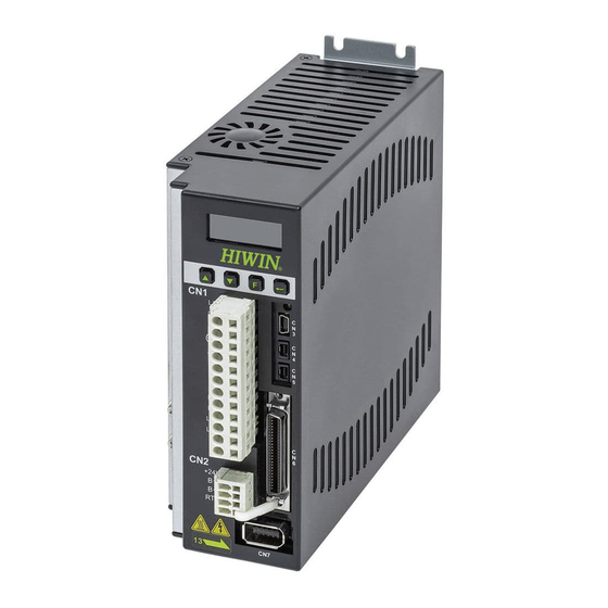
D2 Drive User Guide v1.8 4. Wiring 4.1. System configuration and wiring This chapter describes the system configuration of drive and the function of each connector. 4.1.1. System wiring diagram The following figure shows the name, function, and specification of each drive connector . - Page 47 D2 Drive User Guide v1.8 4. Wiring Fig. 4-2 CN8-out CN8-in CN13 CN14 (b) Extension I/O module (a) EtherCAT module Fig. 4-3 HIWIN Mikrosystem Corp.
- Page 48 D2 Drive User Guide v1.8 4. Wiring Table 4-1 Item Name Connector Description L1, L2: Single-phase 200-240 Vac, 50/60Hz AC main power L1, L2, L3: Three-phase 200-240 Vac, 50/60Hz Frame A-D: CN1 cable (The frame D model is only allowed connecting to...
-
Page 49: Cn1 Power
D2 Drive User Guide v1.8 4. Wiring 4.1.2. CN1 power The pin assignment of CN1 for frame A-C models is different with that for the frame D model. Check the pin assignment for each model before use. Descriptions of CN1 power wiring include: single/three-phase power input, motor power output (frame A-C), regenerative resistor wiring, single-phase control power input, and DC reactor wiring (frame D). - Page 50 D2 Drive User Guide v1.8 4. Wiring (2) Frame D Connector model: TE Connectivity 1-2229794-1 (female). The ground wire of main power should be connected to the drive housing. Fig. 4-6 CN1 connector type for frame D model Table 4-3...
- Page 51 D2 Drive User Guide v1.8 4. Wiring 4.1.2.3. Regenerative resistor wiring The regenerative resistor is optional. However, the frame D model has one internal regenerative resistor (13 Ω/100 W). Install it according to the actual application. (1) Frame A-C mega-fabs...
- Page 52 D2 Drive User Guide v1.8 4. Wiring Caution ● Wiring and the related inspection must be done by the professional technician. ● Turn off the power before wiring or inspection to avoid electric shock and other dangers. ● After the power is turned off, do not touch power terminals for a short time period (at least 5 minutes), since the power in the drive remains high.
-
Page 53: Cn2 Brake/Motor Power
D2 Drive User Guide v1.8 4. Wiring 4.1.3. CN2 brake/motor power For frame A-C models, CN2 is the brake connector; while for the frame D model, CN2 is the motor power connector. Check the pin assignment for each model before use. It is suggested that the brake power should be independent power and does not use the same power source with other power. -
Page 54: Cn3 Usb Communication
Use the mini USB to connect with PC for monitoring drive, doing test runs, or writing parameters, and so on. The corresponding operation please refers to Section 5. Wiring diagram of mini USB communication Use HIWIN cable with the shielding network. Its model is “USB 2.0 Type A to mini-B 5-pin (1.8M)”. Fig. 4-13... -
Page 55: Cn5 Modbus Communication/Safety Function
D2 Drive User Guide v1.8 4. Wiring Table 4-5 Function Description DATA+ RS485 Modbus communication DATA- Reserved Digital ground reference (2) Frame D Connector model: TE Connectivity 2040008-1 (female). (a) RS485 (female connector) (b) RS485 (male connector) Fig. 4-16 Table 4-6... -
Page 56: Cn6 Control Signal
D2 Drive User Guide v1.8 4. Wiring Table 4-7 Function Description Not wiring. Not wiring. SF1- Two independent circuits for turning off the SF1+ operation signal of power module, so as to turn SF2- off the motor current. SF2+ EDM- Output signal for monitoring the status of safety function. - Page 57 N/A or I10 D2 model: N/A; D2T model: I10. General-purpose output signal (programmable function) D2 model: N/A; D2T model with the frame A, B, or C: O5+; N/A or O5+ D2T model with the frame D: brake output/O5+. D2 model: N/A; D2T model with the frame A, B, or C: O5-;...
-
Page 58: Cn7 Encoder
D2 Drive User Guide v1.8 4. Wiring 4.1.8. CN7 encoder Press and pull clamps on both sides to remove CN7 connector. Press and pull these clamps to remove CN7 connector (a) SCR connector 10 pin (male) (b) SCR connector 10PIN (female) Fig. -
Page 59: Cn13/Cn14 Extension I/O Signal
D2 Drive User Guide v1.8 4. Wiring 4.1.10. CN13/CN14 extension I/O signal CN13 and CN14 are 26-pin SCSI connectors. Fig. 4-21 Table 4-11 Specification of extension I/O module Connector Function Quantity Specification Digital input Suitable for power system between 9 and 28 Vdc. -
Page 60: Drive Accessories
D2 Drive User Guide v1.8 4. Wiring 4.2. Drive accessories (1) Motor power cable Table 4-13 Part name Part No. Description HVPS04AA□□MB Suitable for 50 W - 750 W motor, without brake, flexible. Suitable for 1KW motor, without brake, straight connector, HVPM04BA□□MB... - Page 61 D2 Drive User Guide v1.8 4. Wiring denotes the cable length as follows: Table 4-16 Wire length (m) Note: The encoder cable shall be chosen to match with the motor encoder. (3) Control signal cable Table 4-17 Part name Part No.
- Page 62 D2 Drive User Guide v1.8 4. Wiring (5) Connector kit Table 4-19 D2 Drive model Model No. Description Quantity CN1: Connectors of AC power, motor power, regenerative resistor, and control power. 12 pins, pitch 5 mm, Wago 721-112/026-000. CN2: Brake connector. 4 pins, pitch 3.5 mm...
- Page 63 D2 Drive User Guide v1.8 4. Wiring (7) Regenerative resistor Table 4-21 Part name Model No. Resistance value Rated power/peak power 68 Ω 100W/500W Regenerative resistor 120 Ω 300W/1500W (8) Connector specifications Table 4-22 Connector specifications for frame A-C models...
-
Page 64: Main Power Wiring
D2 Drive User Guide v1.8 4. Wiring 4.3. Main power wiring Caution ● Wiring and the related inspection must be done by the professional technician. ● Turn off the power before the wiring or inspection to avoid electric shock and other dangers. -
Page 65: Ac Power Wiring (Three-Phase)
D2 Drive User Guide v1.8 4. Wiring 4.3.2. AC power wiring (three-phase) It is recommended to use the three-phase filter of FN3025HL-20-7. Emergency Stop mega-fabs D2 Series drive Filter 3-phase 200~240VAC 50/60Hz Earth Fig. 4-23 Table 4-25 FN3025HL-20-71 filter Maximum continuous operation voltage... -
Page 66: Multiple Drives Connection
D2 Drive User Guide v1.8 4. Wiring 4.4. Multiple drives connection Caution: Do not use the power connector on the drive to connect the power supply between drives in parallel. Emergency Stop mega-fabs D2 Series drive Filter 3-phase 200~240VAC 50/60Hz... - Page 67 : Multiple of rated current for the maximum rated current among drives; K: Demand rate; 1 if it cannot be determined. Example: If five D2-0123--A and one D2-0423--B drives are used, (assuming that C and C are 2) Not started at the same time: I = (1.5×5 + 4.1 - 4.1)×1 + 4.1×2 = 15.7 A...
-
Page 68: I/O Signal Wiring
General-purpose inputs of D2-series drives adopt the optical-coupler input interface suitable for the voltage system of 12 - 24 Vdc. D2 (D2T) model has the total of 9 (10) general-purpose inputs with one COM port and suitable for Sink or Source connection at the same time. The default function of I3 is “Axis Enable”. -
Page 69: Digital Output Wiring
4.5.2. Digital output wiring General-purpose outputs of D2-series drive adopt the output interface of optical-coupler Darlington suitable for the voltage system of less than 24 Vdc. D2 (D2T) model has 4 (5) general-purpose outputs. Each output has an independent Darlington open-collector circuit. - Page 70 D2 Drive User Guide v1.8 4. Wiring (2) Output wiring example via optical couplers Fig. 4-31 HIWIN Mikrosystem Corp.
-
Page 71: Wiring Examples For Control Commands
D2 Drive User Guide v1.8 4. Wiring 4.6. Wiring examples for control commands 4.6.1. System wiring diagram for pulse command The position mode can accept three formats of pulse command from the host controller. Refer to Section 3.1.1 for more information. - Page 72 D2 Drive User Guide v1.8 4. Wiring 4.6.1.1. Differential interface Wiring example for the host controller having the differential interface: General-purpose output; mega-fabs its function can be High-speed pulse D2 Series Drive assigned by the user. command Host controller (4 Mpps or less)
- Page 73 D2 Drive User Guide v1.8 4. Wiring 4.6.1.2. Sink (NPN) interface with current-limit resistances Wiring example for the host controller having the NPN interface with current-limit resistances: General-purpose output; Low-speed pulse its function can be mega-fabs command assigned by the user.
- Page 74 D2 Drive User Guide v1.8 4. Wiring 4.6.1.3. Sink (NPN) interface without current-limit resistances Wiring example for the host controller having the NPN interface without current-limit resistances: Low-speed pulse General-purpose output; command mega-fabs its function can be (500 Kpps or less) D2 Series Drive assigned by the user.
- Page 75 D2 Drive User Guide v1.8 4. Wiring 4.6.1.4. Source (PNP) interface with current-limit resistances Wiring example for the host controller having the PNP interface with current-limit resistances: Low-speed pulse General-purpose output; command mega-fabs its function can be Host controller (500 Kpps or less) D2 Series Drive assigned by the user.
- Page 76 D2 Drive User Guide v1.8 4. Wiring 4.6.1.5. Source (PNP) interface without current-limit resistances Wiring example for the host controller having the PNP interface without current-limit resistances: Low-speed pulse command General-purpose output; (500 Kpps or less) Host controller mega-fabs its function can be...
- Page 77 D2 Drive User Guide v1.8 4. Wiring 4.6.1.6. 5V TTL interface Wiring example for the host controller having the 5V TTL interface: Low-speed pulse command General-purpose output; mega-fabs (500 Kpps or less) General output its function can be D2 Series Drive...
- Page 78 D2 Drive User Guide v1.8 4. Wiring Note: The signal logic of pulse command accepted by D2 drive is shown as follows. Table 4-27 Pulse Positive logic Negative logic command Pulse If the pulse command of host controller is the single-ended negative logic CW/CCW signal, it can be converted to the positive logic CW/CCW signal by using the following wiring.
-
Page 79: System Wiring Diagram For Voltage Command
D2 Drive User Guide v1.8 4. Wiring 4.6.2. System wiring diagram for voltage command The drive can accept the voltage command form the host controller in the velocity and force/torque modes. Refer to Sections 3.1.2 and 3.1.3. for more information. - Page 80 D2 Drive User Guide v1.8 4. Wiring Wiring example for the host controller having the interface of -10 V to +10 V: General-purpose output; mega-fabs its function can be D2 Series Drive Host controller assigned by the user. Velocity mode input...
-
Page 81: System Wiring Diagram For Pwm Command
4. Wiring 4.6.3. System wiring diagram for PWM command In addition to analog voltage command, D2-series drives can also accept the PWM command in the velocity and force/torque modes. The PWM command is classified into single-wire (PWM 50%) and two-wire (PWM 100%) types. Refer to Sections 3.1.2 and 3.1.3 for more information. - Page 82 D2 Drive User Guide v1.8 4. Wiring 4.6.3.2. NPN interface with PWM 100% Wiring example for the host controller having the NPN interface with PWM 100%: General-purpose output; mega-fabs its function can be assigned by the user. D2 Series Drive...
- Page 83 D2 Drive User Guide v1.8 4. Wiring 4.6.3.3. 5V TTL interface with PWM 50% Wiring example for the host controller having the 5V TTL interface with PWM 50%: General-purpose output; mega-fabs its function can be General output assigned by the user.
- Page 84 D2 Drive User Guide v1.8 4. Wiring 4.6.3.4. 5V TTL interface with PWM 100% Wiring example for the host controller having the 5V TTL interface with PWM 100%: General-purpose output; mega-fabs its function can be General output D2 Series Drive assigned by the user.
-
Page 85: Drive Configuration
D2 Drive User Guide v1.8 5. Drive Configuration 5. Drive Configuration Drive Configuration ......................79 5.1. Installation and communication ................80 5.1.1. Setup files ....................80 5.1.2. Communication setup ................. 81 5.1.3. HMI main window ..................83 5.2. Configuration center ..................... 86 5.2.1. -
Page 86: Installation And Communication
Fig. 5-1 If using the installation CD, simply wait for the setup program to run automatically. If using setup files downloaded from HIWIN website (after log in HIWIN website, the file path is “http:// www.hiwinmikro.tw/hiwintree/Product_SubType.aspx?type=D2”), unzip the downloaded file and execute “setup.exe”. The default installation path is “C:\HIWIN\”. Do not try to change this path. -
Page 87: Communication Setup
(3) using CoE communication. This section will introduce the former two methods. As for the last one, refer to the other HIWIN document: “HIWIN CoE Drive User Guide” (log in HIWIN website and download it. The file path is http://www.hiwinmikro.com.tw/hiwintree/Product_SubType.aspx?type=D2). - Page 88 D2 Drive User Guide v1.8 5. Drive Configuration Fig. 5-6 (2) Using mega-ulink communication At the first usage of mega-ulink communication, download and install WinPcap. After installing WinPcap is done, open the “lightening Communication Setup” window described in the previous subsection, as shown in Fig. 5-6. Select the radio button for “Ethercat” and click the “EtherCat”...
-
Page 89: Hmi Main Window
D2 Drive User Guide v1.8 5. Drive Configuration “EtherCat set up” window and click the “Apply” button in the “lightening Communication Setup” window. Fig. 5-8 After the setting is completed, the window of Fig. 5-9 will appear. The number of connected axes can be obtained from the information in the window. - Page 90 D2 Drive User Guide v1.8 5. Drive Configuration Main Drive toolbar connection area Status display area Click the right mouse button Axis Error at the axis name message name to show display this menu. area Warning message display area Connection...
- Page 91 5. Drive Configuration Fig. 5-12 Note: When Lightening 0.144 (inclusive) or older version is used to connect with D2 model, or Lightening 0.180 (inclusive) or older version is used to connect with D2T model, the message for installation error will appear after connecting, as shown in Fig. 5-13. Since these HMI versions do not contain the firmware version for these drives, Lightening cannot identify them.
-
Page 92: Configuration Center
The location of this button is shown in Fig. 5-14. Fig. 5-14 Following setting steps must be done before using D2 drive to drive the motor successfully. (1) Motor type: Set the used motor type and the corresponding parameters for the motor hardware. - Page 93 D2 Drive User Guide v1.8 5. Drive Configuration Operation parameters setting area Motor parameter setting area Fig. 5-15 Motor configuration page for Lightening 0.177 or less. ZeroTune parameters setting area Fig. 5-16 Motor configuration page for Lightening 0.178 or above...
-
Page 94: Encoder Configuration
The encoder configuration page is shown in Fig. 5-17. Select or set the correct type and parameters of encoder on this page. To work with the host controller, D2 drive can output encoder signals besides receiving encoder signals. It provides the buffered encoder output or emulated encoder output. - Page 95 10,000 counts/rev. (2) 17-bit serial encoder For HIWIN AC servo motor with the serial encoder, it does not need to set encoder parameters, since they are already saved in the encoder, as shown in Fig. 5-18. For example, for the 9-th bit of motor model name being 4 or 6, the program will automatically read encoder parameters and show the resolution being 131,072 counts/rev.
- Page 96 D2 Drive User Guide v1.8 5. Drive Configuration A. When the option of “Dual loop” is not checked, the setting method for the serial encoder is adopted. The drive will read encoder parameters automatically, and users do not set them by manual. The option of “Use emulated encoder” only can be set in the “Encoder output”...
- Page 97 Fig. 5-21 Encoder configuration page for customized encoder 5.2.2.3. Encoder output setting D2 drive sends out the encoder signal with the AqB square wave via CN2. It can be connected to the host controller if needed. Checking “Use buffered encoder” or “Use emulated encoder”...
- Page 98 D2 Drive User Guide v1.8 5. Drive Configuration Fig. 5-22 Encoder output setting area Fig. 5-23 Buffered encoder output (2) Emulated encoder output When this option is selected, the drive will multiply the received encoder position by “Scaling” and send the result to the host controller. If the ratio is 1:1, the drive will directly output the encoder signal based on the adopted encoder and the set resolution.
- Page 99 D2 Drive User Guide v1.8 5. Drive Configuration (3) Output Z-phase signal to host controller For AC servo motor with the 17-bit encoder, the Z-phase signal can be sent out to the host controller by setting the encoder output to “Use emulated encoder”, as shown in Fig.
-
Page 100: Operation Mode Configuration
The closed-loop control is done by the drive. D2 drive supports three formats of pulse command. Also, the electronic gear ratio is allowed to be set for the high-speed application. - Page 101 D2 Drive User Guide v1.8 5. Drive Configuration Dead band definition Output Input Dead band Fig. 5-29 (3) Force/Torque mode To work with the host controller sending analog commands or PWM commands, the other operation mode is the force/torque mode. Only the ratio (“Scaling”) between the external command and current has to be set, where the unit is the corresponding relationship between 1V and Ampere, or between Full PWM and the maximum current.
-
Page 102: Modbus Communication Configuration
D2 Drive User Guide v1.8 5. Drive Configuration 5.2.4. Modbus communication configuration The configuration page for the Modbus communication is given in Fig. 5-31. Only the drive with the Modbus module has this configuration page. Fig. 5-31 (1) Modbus Slave address Set the slave address of Modbus communication. -
Page 103: Completing Configuration Procedure
D2 Drive User Guide v1.8 5. Drive Configuration 5.2.5. Completing configuration procedure After completing the motor, encoder, and operation mode configurations, click the “OK” button at the bottom of window to show Fig. 5-32. This window gives parameters before setting and after setting for the comparison. -
Page 104: Auto Phase Center
This method is for the 9-th bit of drive model name being 0, and the 9-th bit of motor model name being 5. For example, the drive model name is D2-0423-S-B4 and the motor model name is FRLS4020506A. -
Page 105: Setting Procedure
D2 Drive User Guide v1.8 5. Drive Configuration 5.3.3. Setting procedure This section describes the procedure of auto phase initialization for LSWIR. As for STABS, it can use the same procedure for LSWIR. Operation Step Graphical (HMI) description Setting phase initialization method:... -
Page 106: Troubleshooting
D2 Drive User Guide v1.8 5. Drive Configuration 5.3.4. Troubleshooting ※ Confirm that the motor power cable and encoder feedback cable have been correctly connected. ※ Confirm that the parameter setting for the encoder or motor is correct, such as the encoder resolution or the number of motor pole pair. -
Page 107: Auto Tune Center
Fig. 5-35. Fig. 5-35 Note. The function of auto tune center only supports D2-serial drives (included D2T model). It is applicable to Lightening 0.184 and D2 MDP 0.037 (inclusive) or above, and D2COE MDP 0.113 (inclusive) or above. If the firmware version is not in the above version, the option of in the Lightening main toolbar will be anti-gray and cannot be clicked. - Page 108 D2 Drive User Guide v1.8 5. Drive Configuration Enable/Disable Change the motor direction (Toggle Direction) Fig. 5-37 Auto tune center - enable state A. If the motor is not enabled, all buttons in the tuning area are anti-gray. If the motor is enabled, the “Enable”...
- Page 109 D2 Drive User Guide v1.8 5. Drive Configuration Auto tune mode Stiffness Fig. 5-38 Auto tune center - setting mode Table 5-4 Stiffness Description Stiffness is small. Suitable for the low rigidity, such as the belt and other 1. Soft mechanisms.
-
Page 110: Announcements
D2 Drive User Guide v1.8 5. Drive Configuration tuning is finished (the execution time is about 25 seconds). After that, if the light keeps green, it indicates that the auto gain tuning is successful; while if the light keeps red, it indicates that the auto gain tuning is failed. - Page 111 D2 Drive User Guide v1.8 5. Drive Configuration If the motor still vibrates abnormally after performing the auto gain tuning process many times, please collect the following informantion and consult with the customer-service enginner to help troubleshooting the problem. “...
-
Page 112: I/O Center
I/O center. Click the drop-down button ( ) in the input function menu to select the digital input pin and its function, as shown in Fig. 5-40. D2 (D2T) model has 9 (10) digital inputs. Fig. 5-40 Input function menu (1) Status indicator light If the status indicator light is green, it means that the corresponding input pin has been activated. - Page 113 D2 Drive User Guide v1.8 5. Drive Configuration Inhibit Pulse Inhibiting the pulse command. Level trigger Command Switch HI/LO Pulse Switching between the high-speed and PSEL Level trigger Input low-speed pulse input channels. Emergency stop. The drive enters the Abort Motion...
- Page 114 D2 Drive User Guide v1.8 5. Drive Configuration Table 5-7 Default input setting for D2 drive CoE model Not CoE model Signal Inverse Position Velocity Force/torqu Stand-alone Stand-alone mode mode e mode mode mode Inhibit Pulse Zero Speed Start Homing...
- Page 115 D2 Drive User Guide v1.8 5. Drive Configuration The external signal is triggered to stop the motor by using the emergency-stop deceleration. When the input state of “Abort Motion” is True (the state light is green), the drive will decelerate the motor to stop by using the emergency-stop deceleration (Dec.
- Page 116 D2 Drive User Guide v1.8 5. Drive Configuration Input Switch to secondary mode Operation mode function Symbol Default input Circuit Refer to 4.5.1 Function description: Switch the operation mode via the I/O signal from the host controller. Instructions: Set the operation mode in the “Mode” tab of configuration center as shown in the following figure.
- Page 117 D2 Drive User Guide v1.8 5. Drive Configuration Input Electronic Gear Select Operation mode Function (DIV1, DIV2) Symbol DIV1, DIV2 Default Input Circuit Refer to 4.5.1 Function description: Switch among four sets of electronic gear ratio. Instructions: Go to the “Mode” tab of configuration center, and select “Position Mode” in “Primary Operation Mode”...
- Page 118 D2 Drive User Guide v1.8 5. Drive Configuration DIV2 DIV1 Numerator Input Inhibit Pulse Command Operation mode function Symbol Default input Circuit Refer to 4.5.1 Function description: Inhibit to receive the pulse command sent by the host controller via triggering this input signal.
- Page 119 D2 Drive User Guide v1.8 5. Drive Configuration Input Switch HI/LO Pulse Input Operation mode function Symbol PSEL Default input None Circuit Refer to 4.5.1 Function description: In the position mode, trigger this input signal through the host controller to switch between the high-speed and low-speed pulse input channels.
- Page 120 D2 Drive User Guide v1.8 5. Drive Configuration Input Switch to secondary vpg Operation mode function Symbol JSEL Default input None Circuit Refer to 4.5.1 Function description: Switch between velocity loop gains. Instructions: Different velocity loop gains can be set in the “Schedule Gains + vpg” tab of “Advanced gains”...
- Page 121 D2 Drive User Guide v1.8 5. Drive Configuration Brake start speed (vel_stop) is not related to Motor speed the rotation direction of motor. It is applicable to the forward and reversal directions. vel_stop Forward direction Analog input voltage Dead band...
- Page 122 D2 Drive User Guide v1.8 5. Drive Configuration Input Clear Error Operation mode function Symbol Default input Circuit Refer to 4.5.1 Function description: Clear error message. Instructions: The error message will be cleared when the input state of “Clear Error” is changed from False to True.
-
Page 123: Digital Output
5. Drive Configuration 5.5.2. Digital output D2 model provides 5 sets of programmable digital output. Here, 4 sets (O1 - O4) are general- purpose outputs located on the CN6 connector. The fifth set (CN2 BRK) is specially designed as the brake output and can also be used as the general-purpose output. D2T model has more than one general-purpose output (O5) located on the CN6 connector. - Page 124 D2 Drive User Guide v1.8 5. Drive Configuration cancelled, click the “Not Configured” button. After selecting the desired function, click the “Apply” button to complete the setting. On the other hand, click the “Cancel” button to discard the setting. In the “Errors” category, there is one “Set all errors” button. It is recommended to use this button at selecting all errors in the “Errors”...
- Page 125 The encoder battery is no power. Replace the battery. warning The absolute encoder feedbacks an error absolute position. Wrong absolute position Reset the home position. Table 5-9 Default output setting for D2 drive CoE model Not CoE model Signal Inverse...
- Page 126 D2 Drive User Guide v1.8 5. Drive Configuration Output Zero Speed Detected Operation mode function Symbol ZSPD Default output Circuit Refer to 4.5.2 Function description: The drive outputs this signal when the motor speed is close to zero. Instructions: The so-called “speed closed to zero” means that the motor speed is less than the threshold set by the parameter “vel_stop”.
- Page 127 D2 Drive User Guide v1.8 5. Drive Configuration Output Errors Operation mode function Symbol Default output Circuit Refer to 4.5.2 Function description: Output the error status. Instructions: “Errors” can be set in the “Outputs” tab of I/O center (The default is O2).
-
Page 128: Analog Output
D2 Drive User Guide v1.8 5. Drive Configuration 5.5.3. Analog output D2T model has two analog outputs, located on the CN6 connector, which can be used to monitor the motor speed (pin 42) and motor torque (pin 43). The output voltage range is from -10 V to 10 V, and the output resolution is 16 bits. -
Page 129: Extension I/O
D2 Drive User Guide v1.8 5. Drive Configuration 5.5.4. Extension I/O For D2 drive with the extension I/O module, parameters shown in Table 5-11 can be used to set the voltage level for each extension I/O pin. Table 5-11 Extension I/O parameters... -
Page 130: In-Position Signal Setting
When the motor moves to the target position, there will be a small period of settling, called the settling time. Then, the motor enters the target radius. D2 drive provides the functional interface of in-position to observe whether the motor has reached the target position by setting “Target radius”... - Page 131 D2 Drive User Guide v1.8 5. Drive Configuration Debounce time setting The motor positioning may have the overshoot phenomenon, resulting in that the “In-Position” signal will be instable before the motor reaches the target position. This can be resolved by setting “Debounce time”.
-
Page 132: Homing Configuration
D2 Drive User Guide v1.8 5. Drive Configuration 5.7. Homing configuration Click to appear the window of application center, as shown in Fig. 5-47. The first tab is the homing configuration page of “Homing”. Fig. 5-47 Homing configuration page There are 5 basic parameters for the homing configuration, as shown in the following table. - Page 133 D2 Drive User Guide v1.8 5. Drive Configuration Home offset (1) Homing mode for incremental encoder This method is only applicable to homing modes (1) and (2) described above. When “Home Offset” is set to a nonzero value, the home position found in the original condition is offset by a distance.
-
Page 134: Go Left And Right For Homing
5. Drive Configuration 5.7.1. Go left and right for homing This function is a kind of multi-function homing mode built-in D2 drive. By searching the left and right conditions, the home position can be determined. The main method is to find the midpoint of two boundaries as the home position. - Page 135 D2 Drive User Guide v1.8 5. Drive Configuration Select one of following items for the left or right side condition. (1) None: Non-search; (2) End Stop: Search the end stop; (3) Limit Switch: Search the limit switch. Searching end stop should be carried out with parameters ○...
-
Page 136: Use Near Home Sensor/Index For Homing
D2 Drive User Guide v1.8 5. Drive Configuration (2) If the option of “Search Index Signal” is checked and there are multiple indexes in the stroke, the drive will take the index closest to “End Stop” or “Right Limit Switch” as the home position. - Page 137 D2 Drive User Guide v1.8 5. Drive Configuration Table 5-15 Parameter Option Description Initial Left Search first in the left direction. ○ movement Right Search first in the right direction. direction Search at the lower homing speed. Set it in...
-
Page 138: Use Multi-Turn Absolute Encoder For Homing
D2 Drive User Guide v1.8 5. Drive Configuration Motor Negative limit switch Near home sensor Positive limit switch Index signal Fig. 5-59 5.7.3. Use multi-turn absolute encoder for homing Due to the characteristic of multi-turn absolute encoder, the drive can obtain the absolute position of motor at any time. -
Page 139: Use Homing Methods In Cia 402 Protocol
D2 Drive User Guide v1.8 5. Drive Configuration 5.7.4. Use homing methods in CiA 402 protocol For the CoE model, the software version of Lightening 0.185 or above supports this homing mode. The configuration page is shown in Fig. 5-61, where the green line represents the faster homing speed, and the orange line represents the slower homing speed. - Page 140 D2 Drive User Guide v1.8 5. Drive Configuration Description Explanation Homing on home switch and index pulse – positive initial motion, left edge of home switch, left-side index: (1) Outside home switch: The motor searches the left edge of home switch in the positive direction by using the faster speed.
- Page 141 D2 Drive User Guide v1.8 5. Drive Configuration Description Explanation Homing on home switch and index pulse – positive initial motion, right edge of home switch, right-side index: The motor searches the right edge of home switch in the positive direction by using the faster speed.
- Page 142 D2 Drive User Guide v1.8 5. Drive Configuration Description Explanation Homing on home switch and index pulse – negative initial motion, left edge of home switch, right-side index: The motor searches the left edge of home switch in the negative direction by using the faster speed.
- Page 143 D2 Drive User Guide v1.8 5. Drive Configuration Description Explanation Homing on hard stop and index pulse – positive initial motion, The motor searches the hard stop in the positive direction by using the faster speed. After searched, the motor searches the index pulse in the negative direction by using the slower speed.
-
Page 144: Save Parameters To Flash And Recover To Factory Default
D2 Drive User Guide v1.8 5. Drive Configuration 5.8. Save parameters to Flash and recover to factory default 5.8.1. Save parameters to Flash (“Save parameters from amplifier RAM to Flash”) in the HMI main window to save Click the current parameter in the memory. Parameters will not disappear even if the drive’s power is turned off. - Page 145 D2 Drive User Guide v1.8 5. Drive Configuration Fig. 5-64 For the version of Lightening 0.186 (inclusive) or above, select “Set amplifier to factory default” in the “Tools” menu of HMI main window. Then, the window of Fig. 5-65 appears to ask if users want to set the amplifier to factory default.
-
Page 146: Parameter Setting Examples Via Hmi
Select the “Position Mode” option in the “Mode” tab. (2) Pulse format selection D2 drive supports three types of command format, referring to Section 3.1.1. Use following steps to select the pulse format via HMI. Step Graphical (HMI) description Operation In the “Mode”... - Page 147 D2 Drive User Guide v1.8 5. Drive Configuration (3) Electronic gear ratio setting D2 drive provides four sets of electronic gear ratio, referring to Section 5.5.1. Use following steps to set the electronic gear ratio via HMI. Step Graphical (HMI) description...
-
Page 148: Velocity Mode
D2 Drive User Guide v1.8 5. Drive Configuration 5.9.2. Velocity mode D2 drive can transfer the voltage command and PWM command to the velocity command, referring to Section 3.1.2. The velocity mode configuration includes: the mode selection and input command format setting. -
Page 149: Force/Torque Mode
“Send to RAM” button to save parameters to drive RAM. 5.9.3. Force/Torque mode D2 drive can transfer the voltage command and PWM command to the current command, referring to Section 3.1.2. The force/torque mode configuration includes: the mode selection and input command format setting. - Page 150 D2 Drive User Guide v1.8 5. Drive Configuration Select the “Velocity Mode” option in the “Mode” tab. (2) Input command format setting Use following steps to set the input command format via HMI. Step Graphical (HMI) description Operation In the “Mode” tab, select the input command format on the “Command Types”...
-
Page 151: Stand-Alone Mode
D2 Drive User Guide v1.8 5. Drive Configuration After the window for parameters confirmation appears, click the “Send to RAM” button to save parameters to drive RAM. 5.9.4. Stand-alone mode In the stand-alone mode, the drive will execute the internal path planning to drive the motor, referring to Section 3.1.4. - Page 152 D2 Drive User Guide v1.8 5. Drive Configuration After the window for parameters confirmation appears, click the “Send to RAM” button to save parameters to drive RAM. HIWIN Mikrosystem Corp.
-
Page 153: Drive Tuning
D2 Drive User Guide v1.8 6. Drive Tuning 6. Drive Tuning Drive Tuning ......................... 147 6.1. Status display and quick view ................148 6.1.1. Status display ................... 148 6.1.2. Quick view ....................148 6.1.3. Software shortcuts ..................149 6.2. Performance center .................... 150 6.3. -
Page 154: Status Display And Quick View
D2 Drive User Guide v1.8 6. Drive Tuning 6.1. Status display and quick view In Lightening HMI, the status display and “Quick view” are two auxiliary tools, which are indispensable in the tuning process. They can help to know the drive status at any time and present many important parameter values in the motion control. -
Page 155: Software Shortcuts
Fig. 6-3 Unit setting menu 6.1.3. Software shortcuts There are two function shortcuts in HMI for D2 drive: F6 and F12. They are only available if Lightening HMI is active for Windows operation system. - F6: Move the Lightening main window to the top level. -
Page 156: Performance Center
D2 Drive User Guide v1.8 6. Drive Tuning 6.2. Performance center Most of tuning procedures are centered around the performance center. After completing the setting in Section 5.3. Auto phase center or Section 5.4. Auto tune center, the motor is ready for test runs. - Page 157 D2 Drive User Guide v1.8 6. Drive Tuning The performance center has the function of measuring the settling time. The target radius of position error and debounce time for settling time can be set via “Target radius”, referring to Section 5.6. In-position signal setting. During motion, the servo gain (“Primary CG”) can be tuned to meet the requirement of settling time.
- Page 158 D2 Drive User Guide v1.8 6. Drive Tuning ○ ○ ○ ○ ○ ○ ○ ○ ○ ○ ○ ○ ○ Fig. 6-6 Performance center – “Position” tab ○ Enable: Enable the motor. ○ Disable: Disable the motor. ○ Zero: Set the current position to the zero position.
-
Page 159: Scope
D2 Drive User Guide v1.8 6. Drive Tuning 6.3. Scope D2 drive provides a “Scope” graphics oscilloscope to help users to observe all significant physical quantities during the tuning process to judge the tuning result. In addition, this feature or the “Set can be used to find the error clue when the drive cannot be operated. - Page 160 D2 Drive User Guide v1.8 6. Drive Tuning Table 6-1 Symbol Name Description The switch of “Scope”. When the switch is turned Scope On/Off (PageDown) off and then turned on, the scope will re-capture the data. Change the display waveform mode. There are View in paper mode (Ctrl+T) the “Normal”...
-
Page 161: Data Collection
D2 Drive User Guide v1.8 6. Drive Tuning 6.4. Data collection In addition to using “Scope” to observe physical quantities of each drive, there is a tool to provide more setting options for data capture, and more advanced graphical display and processing functions. -
Page 162: Data Collection Via Pdl
D2 Drive User Guide v1.8 6. Drive Tuning is on standby. When the motor speed is greater than 0, it will start to collect the data; while when the motor speed is less than 0, it will stop to collect the data. After the data collection is completed, click the “Graph”... -
Page 163: Plot View
D2 Drive User Guide v1.8 6. Drive Tuning 6.5. Plot view The “Plot view” function is built on the “Data collection” function. It draws the data collected by “Data collection” into graphics. “Plot view” has a powerful analysis function to provide the measurement and calculation. - Page 164 D2 Drive User Guide v1.8 6. Drive Tuning Fig. 6-10 (2) Show or hide physical quantities If the physical quantity is unchecked, the graphic display area will hide the graph of this physical quantity. As shown in Fig. 6-11, it is the example of two physical quantities being unchecked.
- Page 165 D2 Drive User Guide v1.8 6. Drive Tuning : Undo zoom. : Redo zoom. : Cancel all zoom-in displays. : Zoom in the graph between the red solid-line and dotted-line cursors on the Y axis. : Cancel the zoom-in action on the Y axis.
- Page 166 D2 Drive User Guide v1.8 6. Drive Tuning (5) Zoom in/out on the Y axis To zoom in on the Y axis, press and hold the “Ctrl” button and the left mouse button to move the red solid-line cursor or the right mouse button to move the dotted-line cursor to frame a suitable interval, as shown in Fig.
-
Page 167: Save/Open File
D2 Drive User Guide v1.8 6. Drive Tuning Parameters are not automatically adjusted to fit the graph. Slider movement direction. Fig. 6-16 (6) dt, 1/dt, dSamp When the interval is framed by using the blue solid-line and dotted-line cursors, values of “dt”, “1/dt”, and “dSamp”... -
Page 168: Mathematical Operation
D2 Drive User Guide v1.8 6. Drive Tuning Fig. 6-17 Save as a .gpp file 6.5.3. Mathematical operation “Plot view” also provides some math formulas for the operation of physical quantities, such as the integration, differentiation, addition, multiplication,…, etc. This allows users to calculate and observe the calculated result directly in “Plot view”. - Page 169 D2 Drive User Guide v1.8 6. Drive Tuning set its color. Finally, click the “Create” button to generate the physical quantity (“lin_1”) of “pos_err” plus “vel_fbf”, as shown in Fig. 6-20. Other mathematical operations are the same as that for addition. Not repeat them here. The related icon on the main toolbar area is described as follows.
- Page 170 D2 Drive User Guide v1.8 6. Drive Tuning Fig. 6-21 Fig. 6-22 (4) Natural logarithm The natural logarithm function is to express the X axis in the logarithmic form. It is only applicable after the Fourier transform is completed. The related icon on the main toolbar area is described as follows.
-
Page 171: Advanced Gains
The performance of system control can be enhanced via the filter. D2 drive provides two filters that can be used simultaneously and set in the form of low pass filter or notch filter. To design a filter, the frequency analyzer is usually used to analyze the system characteristic. - Page 172 D2 Drive User Guide v1.8 6. Drive Tuning Fig. 6-24 Filter (1) Low pass filter The setting of typical low pass filter is given as follows: ○ fr: The cutoff frequency of filter. The unit is Hz. For general applications, a good effect can be achieved at the setting of 500 Hz.
-
Page 173: Acceleration Feed-Forward
D2 Drive User Guide v1.8 6. Drive Tuning (2) Notch Filter When the system has an inappropriate resonance frequency (for example, between 10 and 250 Hz) that cannot be eliminated by the mechanism correction or design enhancement, the notch filter can be used to improve this problem. In general, the notch filter should be set according to the result of frequency analysis. - Page 174 D2 Drive User Guide v1.8 6. Drive Tuning point-to-point motion. Fig. 6-27 Acceleration feed-forward Step 4. Record the maximun of “Command Current” in the acceleration phase, as shown in Fig. 6-28. It can be observed from the figure that “Command Current” is 16 in the acceleration phase.
-
Page 175: Schedule Gains And Velocity Loop Gain
D2 Drive User Guide v1.8 6. Drive Tuning Step 6. Dividing the value obtained in Step 4 by the value obtained in Step 5, Acc feedforward gain = Command Current/Reference Acceleration = 16/950,000 =1.68421*10 Step 7. Enter the result obtained in Step 6 into the “Acc feed forward gain” field, as shown in Fig. - Page 176 Fig. 6-31 Schedule gains (2) Velocity loop gain (vpg) The velocity loop gain (vpg) is an internal control parameter of D2 drive. Normally, the initial value is calculated by parameters set in the configuration center. This value is not to be modified under the normal case.
- Page 177 D2 Drive User Guide v1.8 6. Drive Tuning Step 2. Click the “Enable” button. Step 3. Click the “Run” button to start the frequency analyzer. The motor will be in the low-frequency vibration and then gradually issue a high-frequency sound. After it is completed, a frequency response will be drawn on the window, as shown in Fig.
-
Page 178: Analog Input
D2 Drive User Guide v1.8 6. Drive Tuning vpg is got via the automatic calculation. Cursor line Frequency response line Fig. 6-34 6.6.4. Analog input When the voltage mode is used, the voltage command sent by the host controller may contain the DC bias due to various factors. -
Page 179: Current Loop
D2 Drive User Guide v1.8 6. Drive Tuning 6.6.5. Current loop Gain values of current loop, “Ki” and “Kp”, are basically calculated according to motor parameters when the motor model is selected in the configuration center. They are usually not required for further adjustment. - Page 180 D2 Drive User Guide v1.8 6. Drive Tuning The following is the operation method for finding the vibration frequency and starting the vibration suppression feature. Step 1. Set the pre-planned acceleration, deceleration, speed, and travel. Then make the motor do the back-and-forth motion.
- Page 181 D2 Drive User Guide v1.8 6. Drive Tuning at the toolbar of “Plot view” window to open the operation window for fast Step 5. Click Fourier transform (FFT). Execute FFT on pos_err, as shown in Fig. 6-40. Press this button to start to execute FFT.
- Page 182 D2 Drive User Guide v1.8 6. Drive Tuning In the window, click the left mouse button to drag the solid line to the maximum amplitude. Low-frequency vibration frequency. Fig. 6-42 Fig. 6-43 HIWIN Mikrosystem Corp.
-
Page 183: Friction Compensation
6.6.7. Friction compensation In the operation of drive element, there is always the mechanical friction to affect the efficiency and function of movement. D2-series drives provide a friction compensation method to reduce the effect of friction, as shown in Fig. 6-45. - Page 184 D2 Drive User Guide v1.8 6. Drive Tuning Before using the friction compensation function, the Lightening HMI provides a convenient set of steps. The friction compensation can be successfully added after completing each step. Step 1. Click the “Set scope” button to apper the “Scope” window.
-
Page 185: Loop Constructor
D2 Drive User Guide v1.8 6. Drive Tuning 6.7. Loop constructor “Loop constructor” allows users to confirm the stability of control system. It has spectrum analysis tools, such as Nyquist, Nichols, and Bode, and provides users for adjusting filters and gain values (vpg, vig, ppg, and CG). -
Page 186: Load/Save File
D2 Drive User Guide v1.8 6. Drive Tuning 6.7.1. Load/Save file Before using “Loop constructor” to analyze the control system, the control system and gains must be loaded by selecting the “Load” option in the “File” menu of “Loop constructor” window. -
Page 187: Tool
D2 Drive User Guide v1.8 6. Drive Tuning Fig. 6-50 Loop constructor - save data to file 6.7.2. Tool Spectrum analysis tools of “Loop constructor” can analyze and simulate the Nyquist, Bode, and Nichols diagrams of control system. By using this function, the frequency response of control system can be obtained. - Page 188 D2 Drive User Guide v1.8 6. Drive Tuning 6.7.2.2. Nyquist The “Nyquist” option of “Loop constructor” can analyze and simulate frequency responses of “Vel open loop” (velocity open loop) and “Pos open loop” (position open loop) of control system. Using the check method can select to analyze and simulate the Nyquist diagram of “Velocity open loop”...
- Page 189 D2 Drive User Guide v1.8 6. Drive Tuning Fig. 6-53 Bode plots of velocity close loop and position close loop 6.7.2.4. Nichols The “Nichols” option of “Loop constructor” can analyze and simulate frequency responses of “Vel open loop” and “Pos open loop” of control system. Using the check method can select to analyze and simulate the Nichols diagram of “Vel open loop”...
-
Page 190: Filter
D2 Drive User Guide v1.8 6. Drive Tuning 6.7.3. Filter The control loop of drive provides two filters, which can be used at the same time. They are designed to suppress the high-frequency noise, machine vibration, shortage structure rigidity, and so on. -
Page 191: Gain Tuning
D2 Drive User Guide v1.8 6. Drive Tuning (4) k2: Notch filter = 1 Fig. 6-56 Notch filter 6.7.4. Gain tuning “Loop constructor” provides gain values of velocity loop (vpg, vig) and position loop (ppg), and common gains (CG). Refer to Section 6.6 for more information. These parameters can be used to tune gains to simulate the stability of control system after gain tuning, as shown in Fig. -
Page 192: Spectrum Analysis
D2 Drive User Guide v1.8 6. Drive Tuning (1) Velocity loop Gains of velocity loop are vpg and vig, where vpg is the proportional gain of velocity loop and vig is the integral gain of velocity loop. - vpg: Tuning vpg affects the transient response of velocity loop and increase the bandwidth of velocity loop. -
Page 193: Encoder Signal Confirmation
The signal of digital encoder is comprised of two digital pulses with 90°-phase difference. For D2 drive, this function can be used to check whether the encoder value is correct. For example, move the motor with a known distance in manual to check whether the read “Position”... -
Page 194: Error Map Function
The positioning accuracy is usually measured and corrected by using a laser interferometer, so that the positioning error table can be obtained. D2 drive has an error map function. By inputting and saving the error table to the drive via HMI, the drive can use this information to calculate the compensation value at the fixed distance by using the linear interpolation manner to improve the positioning accuracy. - Page 195 D2 Drive User Guide v1.8 6. Drive Tuning value in the “Error” field is obtained from the error measurement of laser interferometer. For example, when the target position is 100 mm, the laser measurement returns to 100.002 mm. The displayed...
-
Page 196: Enable Error Map
After setting the related parameter of error map described above, the drive has the ability of error compensation. As soon as the motor completes the homing procedure, the drive starts the error map immediately. There are two ways for D2 drive to complete the homing procedure. Just choose one of them to use. -
Page 197: Change Start Position
D2 Drive User Guide v1.8 6. Drive Tuning (see Section 5.8.1). Fig. 6-65 6.9.4. Change start position If it is needed to change the start position of error map, select the “Advanced” option of “View” in the function menu to appear the window of Fig. 6-66. Enter the required start position of compensation in the “Start position”... - Page 198 D2 Drive User Guide v1.8 6. Drive Tuning (1) “Home offset” = 0 and “Start position” = 0 For the setting of both “Home offset” and “ Start position” being zero, the effective range of error map takes the index as the boundary. The area from the index towards positive direction is the mapping effective area;...
- Page 199 D2 Drive User Guide v1.8 6. Drive Tuning Table 6-4 Home Start Mapping effective area offset position Mapping effective area Start position = 100 index + position Drive coordinate = 0 Start position = -100 Mapping effective area -100 + position...
- Page 200 D2 Drive User Guide v1.8 6. Drive Tuning Home Start Mapping effective area offset position Start position Home offset = -100 = 50 Mapping effective area -100 + position index Drive coordinate = 0 Drive coordinate = -50 Start position...
- Page 201 D2 Drive User Guide v1.8 6. Drive Tuning Home Start Mapping effective area offset position Start position = -100 Home offset = -50 Mapping effective area -100 + position Drive index coordinate Drive coordinate = 50 Home offset = -100...
-
Page 202: Backlash Compensation
D2 Drive User Guide v1.8 6. Drive Tuning 6.10. Backlash compensation If the platform moves in a fixed direction and stops, it does not move immediately when it needs to move in the opposite direction. The platform stays at the original position until the motion command is accumulated to a certain amount to start moving. -
Page 203: Lcd Operation
D2 Drive User Guide v1.8 7. LCD Operation 7. LCD Operation LCD Operation ......................197 7.1. LCD function ...................... 198 7.1.1. Panel description ..................198 7.1.2. Operation page description ............... 198 7.2. Parameter initialization via LCD ................200 7.3. Home page ......................202 7.4. -
Page 204: Lcd Function
D2 Drive User Guide v1.8 7. LCD Operation 7.1. LCD function 7.1.1. Panel description Page number Display Axis name Up key Enter key Down key Function key Fig. 7-1 LCD panel Table 7-1 Panel function description Name Function Display Display change parameter values, statuses, parameters, actions, and so on. - Page 205 D2 Drive User Guide v1.8 7. LCD Operation operation mode, pulse format, and other parameters, and to save parameters in the memory to Flash. More than 200 advanced parameters can be set. (4) Actions page It is mainly for the servo enable or disable, continuous motion (Jog), moving to the absolute target position, setting the current position to zero, “Auto Tune”, selecting the...
-
Page 206: Parameter Initialization Via Lcd
D2 Drive User Guide v1.8 7. LCD Operation 7.2. Parameter initialization via LCD When taking an uninitialized new drive, follow steps below to select the motor model name, perform the initialization procedure, and drive the motor via the LCD panel. The example of operation procedure is that the motor model name is FRLS402XX5 and the operation mode is the stand-alone mode (“STNDALON”). - Page 207 D2 Drive User Guide v1.8 7. LCD Operation LEVEL ONE LEVEL TWO 4 MOTRSE 4 MOTRSE LS05XX5 LS05XX5 Use the Up key or Down key to select the motor model name. 4 MOTRSE LV5 100 LS402X5 LV5 100 Tune “ZeroTune” gains.
-
Page 208: Home Page
SVNRDY Servo is not ready. When D2 drive detects the occurrence of error or warning, the error or warning message will be displayed on the second line, as shown in Fig. 7-4. Displayed symbols of error and warning are described in Table 7-4 and Table 7-5, respectively. There are two designs for LCD display. - Page 209 WRN W16 Wrong absolute position Note. Before D2 MDP 0.037 (inclusive) and D2COE MDP 0.113 (inclusive), the abbreviated design is adopted for LCD displayed symbols. After D2 MDP 0.038 (inclusive) and D2COE MDP 0.114 (inclusive), the numbered design is adopted for LCD displayed symbols.
-
Page 210: Display Parameters Page
D2 Drive User Guide v1.8 7. LCD Operation 7.4. Display parameters page In the display parameters page, press the Up key or Down key to change the displayed parameter. The operation flow chart is shown in Fig. 7-5, and the definition of the displayed symbol for each parameter is given in Table 7-6. - Page 211 D2 Drive User Guide v1.8 7. LCD Operation Displayed Physical Quantity Description Unit Symbol 64 I4 Input 4 65 I5 Input 5 66 I6 Input 6 71 I7 Input 7 72 I8 Input 8 67 I9 Input 9 (Note 3)
-
Page 212: Change Parameters Page
D2 Drive User Guide v1.8 7. LCD Operation 7.5. Change parameters page The third page of LCD is the change parameters page, which is used to change the set parameter. The operation can be divided into two zones: common parameter zone and advanced parameter zone. -
Page 213: Save To Flash
D2 Drive User Guide v1.8 7. LCD Operation Table 7-8 Common parameter table (set parameter based on the actual application) Function Description Acceleration Maximum acceleration of motor during motion Deceleration Maximum deceleration of motor during motion Velocity Maximum velocity of motor during motion... -
Page 214: Parameter Edit Function
D2 Drive User Guide v1.8 7. LCD Operation LEVEL ONE LEVEL TWO 3 SAVEFL 3 SAVEFL Dynamic 3 SAVEFL cursor Pressing any key will not have any reaction during the display of “PROCESS.” message. 3 SAVEFL PROCESS. Wait 2 seconds. - Page 215 D2 Drive User Guide v1.8 7. LCD Operation Note. When using the LCD parameter edit mode, the notice of using F key is given as below: (1) Pressing the F key for less than one second switches the operation of Up key and Down key between moving cursor and changing parameter value.
- Page 216 D2 Drive User Guide v1.8 7. LCD Operation (Space) Fig. 7-10 Number switching sequence in the parameter edit mode HIWIN Mikrosystem Corp.
-
Page 217: Advanced Parameter Zone
D2 Drive User Guide v1.8 7. LCD Operation 7.5.3. Advanced parameter zone Use following steps to enter the advanced parameter zone. Step 1. Press the Down key to the “+++” page first, and then press the Enter key (the static cursor appears in the left side of the second line) to enter the advanced parameter zone. - Page 218 D2 Drive User Guide v1.8 7. LCD Operation Table 7-9 Advanced parameter table (set parameter based on the actual application) Parameter Definition Unit Default Max. Min. Maximum acceleration of motor during Refer to motion 000 X_acc rev/s Section (recommended value: ten times of motor’s maximum velocity)
- Page 219 D2 Drive User Guide v1.8 7. LCD Operation Parameter Definition Unit Default Max. Min. Dead band of velocity command. The X_cmd_ext_v speed command is 0 when the input Volt voltage is less than the set value Current command scale; the output...
- Page 220 D2 Drive User Guide v1.8 7. LCD Operation Parameter Definition Unit Default Max. Min. Enable/Disable the software limit X_sw_pos_pr 0: Disable the software limit ot_en 1: Enable the software limit Enable/Disable the hardware limit X_hw_lim_pro 0: Disable the hardware limit...
- Page 221 D2 Drive User Guide v1.8 7. LCD Operation Parameter Definition Unit Default Max. Min. Initial speed setting for the second X_home_sele homing mode ct_Speed 0: Slower speed 1: Faster speed Searching home method for the second homing option 0: Index signal only...
- Page 222 D2 Drive User Guide v1.8 7. LCD Operation Parameter Definition Unit Default Max. Min. LCD.I5_inv Invert of input 5 LCD.I6_inv Invert of input 6 LCD.I7_inv Invert of input 7 LCD.I8_inv Invert of input 8 LCD.I9_inv Invert of input 9 LCD.I10_inv Invert of input 10* LCD.brk_inv...
- Page 223 D2 Drive User Guide v1.8 7. LCD Operation Parameter Definition Unit Default Max. Min. Stiffness setting for the second generation of Auto tune AT.stiff 1: Soft 2: Normal 3: Rigid Baud rate for the Modbus communication 0: 9,600 (default) 1: 2,400...
- Page 224 D2 Drive User Guide v1.8 7. LCD Operation Parameter Definition Unit Default Max. Min. UserPDL.X_iV PDL parameter which can be saved in - 1) ar [6] Flash UserPDL.X_iV PDL parameter which can be saved in - 1) ar [7] Flash UserPDL.X_iV...
-
Page 225: Actions Page
D2 Drive User Guide v1.8 7. LCD Operation 7.6. Actions page This page allows users to perform functions of enabling or disabling motor, jogging, moving to absolute position, and setting the current position to zero. Besides, it can set the motion velocity and target position. -
Page 226: Enable/Disable
D2 Drive User Guide v1.8 7. LCD Operation 4: ENA/DI Servo SV RDY enable/disable. servo. Set target position 4: MOV PO 4: JOG Jogging. for “MOV2PO” (unit: count). 4: SETZER Start the absolute Set the current 4: MOV2PO position motion and... -
Page 227: Jog
D2 Drive User Guide v1.8 7. LCD Operation LEVEL ONE LEVEL TWO 4 ENA/DI Servo disable DISABLE 4 ENA/DI SVNRDY 4 ENA/DI 4 ENA/DI Servo enable ENABLE SV RDY Fig. 7-14 Operation of servo enable/disable 7.6.2. JOG Use following steps to perform the continuous motion (“JOG”). The operation flow chart is given in Fig. -
Page 228: Absolute Coordinate Motion
(inclusive) or below, the auto gain tuning adopts the first-generation auto tune design. For Lightening 0.184 and D2 MDP 0.037 (inclusive) or above, or D2COE MDP 0.113 (inclusive) or above, the auto gain tuning adopts the second-generation auto tune design described in Section 5.4. -
Page 229: Set Position To Zero
D2 Drive User Guide v1.8 7. LCD Operation LEVEL TWO LEVEL ONE 4 AUTOTU 4 AUTOTU 4 AUTOTU 4 AUTOTU PROCESS. Complete the auto gain tuning. 4 AUTOTU Execute the FINISH! auto gain tuning. Wait 2 seconds. Fig. 7-17 Operation of executing the auto gain tuning 7.6.5. -
Page 230: Parameter Setting Examples Via Lcd
1: Position mode 2: Velocity mode 3: Force/Torque mode (2) Pulse format selection D2 drive supports three types of command format, referring to Section 3.1.1. Use following steps to select the pulse format via LCD. LCD display after Step Used keys... - Page 231 0: Not inverse 1: Inverse (3) High/Low speed pulse channel setting D2 drive provides the high-speed and low-speed pulse inputs for flexible use. Use following steps to set the high-speed or low-speed pulse input via LCD. LCD display after Step...
- Page 232 0: High-speed pulse input 1: Low-speed pulse input (4) Electronic gear ratio setting D2 drive provides four sets of electronic gear ratio, referring to Section 5.5.1. Use following steps to set the electronic gear ratio via LCD. LCD display after...
-
Page 233: Velocity Mode
X_new_sm_fac Smooth factor 7.7.2. Velocity mode D2 drive can transfer the voltage command and PWM command to the velocity command, referring to Section 3.1.2. The velocity mode configuration includes: the mode selection and input command format setting. After all parameters are set, refer to Section 7.5.1 to save parameters to flash. - Page 234 D2 Drive User Guide v1.8 7. LCD Operation Press the Enter key to complete the setting. (2) Input command format setting Use following steps to set the input command format via LCD. LCD display after Step Used keys Operation operation Continue the last setting screen of operation mode.
-
Page 235: Force/Torque Mode
(unit: volt) 7.7.3. Force/torque mode D2 drive can transfer the voltage command and PWM command to the current command, referring to Section 3.1.2. The force/torque mode configuration includes: the mode selection and input command format setting. - Page 236 D2 Drive User Guide v1.8 7. LCD Operation Press and hold the Down key to go to the “+++” page. Press the Enter key to enter the advanced parameter zone. Press and hold the Up key to go to LCD No.
-
Page 237: Stand-Alone Mode
D2 Drive User Guide v1.8 7. LCD Operation 7.7.4. Stand-alone mode In the stand-alone mode, the drive will execute the internal path planning to drive the motor, referring to Section 3.1.4. The stand-alone mode configuration includes the mode selection. After all parameters are set, refer to Section 7.5.1 to save parameters to flash. - Page 238 D2 Drive User Guide v1.8 7. LCD Operation (This page is intentionally left blank.) HIWIN Mikrosystem Corp.
-
Page 239: Protection Function
D2 Drive User Guide v1.8 8. Protection Function 8. Protection Function Protection Function ....................... 233 8.1. Motion protection ....................234 8.2. Position and velocity errors protection ..............237 8.2.1. Position error limit ..................237 8.2.2. Position error and velocity error warnings ..........237 8.3. -
Page 240: Motion Protection
D2 Drive User Guide v1.8 8. Protection Function 8.1. Motion protection The main function of motion protection is to limit or specify the maximum speed, maximum acceleration, maximum deceleration, emergency stop deceleration of motor output during motor movement. When the speed and acceleration corresponding to the pulse command or voltage command sent from the host controller are too high, the protection function is activated and the motion characteristic is limited to the set value. - Page 241 D2 Drive User Guide v1.8 8. Protection Function value multiplied by 10 times, to avoid being limited by the motion protection function. If this action is ignored, the desired speed or acceleration/deceleration may not be achieved when the motion command is sent from the host controller.
- Page 242 D2 Drive User Guide v1.8 8. Protection Function Reference velocity 100% Before filter After filter Time Deceleration time Acceleration time Filter time constant Fig. 8-3 The value of “Smooth factor” is between 0 and 500. The higher the value is, the smaller the impact is.
-
Page 243: Position And Velocity Errors Protection
Fig. 8-5 8.2.2. Position error and velocity error warnings In addition to the setting of position error limit described above, D2 drive also provides an early warning function. When the position error or velocity error exceeds the set value in “Warning windows”, the warning message will be displayed on the “Status”... -
Page 244: Brake Output
8. Protection Function 8.3. Brake output In order to protect the motor and the system structure, D2-series drives provide a brake signal output to actuate an external electromagnetic brake, which is often used in the Z-direction motor actuation. There are some timing motion issues in this application. For example, when the motor moves in the Z direction and the drive receives a disable command, if the brake directly starts at the high speed, the great shock will be generated to damage the mechanism. - Page 245 D2 Drive User Guide v1.8 8. Protection Function Table 8-4 Parameter name Description Delay time of starting brake The maximum time from receiving the disable command to (“delMaxEnToBrk”) starting the brake. Emergency stop deceleration The deceleration of motor brake during emergency stop.
- Page 246 D2 Drive User Guide v1.8 8. Protection Function (a) Enable timing Fig. 8-8 Dynamic brake timing - enable (b) Disable timing at the motor movement Fig. 8-9 Dynamic brake timing – disable at the motor movement HIWIN Mikrosystem Corp.
- Page 247 D2 Drive User Guide v1.8 8. Protection Function (c) Disable timing at the motor stop Fig. 8-10 Dynamic brake timing - disable at the motor stop HIWIN Mikrosystem Corp.
-
Page 248: Limit Protection
Fig. 8-11 8.4.2. Software limit protection In addition to the hardware limit protection, D2 drive also has the software limit protection. It also plays the role of protecting over stroke. When the motor reaches the position of software limit, the drive can only accept the command to move in the opposite direction. - Page 249 D2 Drive User Guide v1.8 8. Protection Function Fig. 8-12 Table 8-5 Parameter name Description enable sw limit To activate the software limit protection. Check it to activate. Lower SW limit Lower software limit position. Upper SW limit Upper software limit position.
-
Page 250: Over Temperature Protection
8.5. Over temperature protection 8.5.1. Soft-thermal protection D2 drive has the function of estimating the motor temperature by using the software. Utilizing the current output to estimate the motor power and then estimate the motor temperature. When it reaches the default value of drive, the drive issues an error message of “Soft-thermal threshold reached”, enters the emergency stop process, and finally disables the motor. -
Page 251: Over Voltage Protection
The regenerative resistor of D2 drive has the turn-on voltage of 370 Vdc and the turn-off voltage of 360 Vdc. Users can refer to the following... - Page 252 D2 Drive User Guide v1.8 8. Protection Function Fig. 8-15 Motor regenerative curve of FRMS752XX Fig. 8-16 Motor regenerative curve of FRMM1K2XX Fig. 8-17 Motor regenerative curve of FRMM2K2XX HIWIN Mikrosystem Corp.
- Page 253 D2 Drive User Guide v1.8 8. Protection Function The regenerative resistor model of HIWIN standard product is given in Table 8-6. Users can use them in series or in parallel according to the requirement. The appearance and size are given in Table 8-7 and Fig. 8-18.
- Page 254 D2 Drive User Guide v1.8 8. Protection Function (This page is intentionally left blank.) HIWIN Mikrosystem Corp.
-
Page 255: Troubleshooting
D2 Drive User Guide v1.8 9. Troubleshooting 9. Troubleshooting Troubleshooting ......................249 9.1. Drive’s status indicator ..................250 Drive’s errors and warnings ................251 9.2. 9.2.1. Status display area on Lightening HMI ............251 9.2.2. LCD status ....................251 9.2.3. -
Page 256: Drive's Status Indicator
D2 Drive User Guide v1.8 9. Troubleshooting 9.1. Drive’s status indicator The drive’s status indictor is LED on the front panel of drive, which shows the current status of drive. Its status is described in the following stable. Status indicator Status indicator Drive’s status... -
Page 257: Drive's Errors And Warnings
9.2. Drive’s errors and warnings 9.2.1. Status display area on Lightening HMI When D2 drive detects an error, in addition to staring the protection mechanism, it also displays the last error message in the error message display area (“Last error”), as shown in Fig. -
Page 258: Errors And Warnings Log
9. Troubleshooting 9.2.3. Errors and warnings log When D2 drive detects an error or warning event, in addition to showing it in the error message display area and warning message display area on the main window, as given in Fig. 9-2, it is also recorded in “Errors and warnings Log”. The opening method is shown in Fig. - Page 259 D2 Drive User Guide v1.8 9. Troubleshooting Refer to Fig. 9-6 for the “Statistics” tab in “Errors and warnings log”. The number of errors or warnings (“Frequency”) occurred in the drive is recorded in this window. This can help users to understand which events occur most frequently and to debug.
-
Page 260: Error At Loading Prm File
D2 Drive User Guide v1.8 9. Troubleshooting 9.2.4. Error at loading PRM file To ensure the compatibility between the loaded PRM parameter file and the drive firmware, Lightening will check if the PRM file is suitable for the current firmware version. When the following error message appears, it means that the PRM file is unsuitable, and need to re-set parameters or replace an appropriate firmware version. -
Page 261: Error Codes And Troubleshooting
D2 Drive User Guide v1.8 9. Troubleshooting 9.3. Error codes and troubleshooting Description Error error code Troubleshooting The short of three motor phases is detected. (1) After power-off, unplug the UVW-phase connector at the drive-side and measure the resistance between each... - Page 262 ERR E09 input is 100 or 220 Vac. The 5V power supply of encoder interface is abnormal. (1) Unplug CN6, CN7, and motor power cable of D2 drive. E10 V5ERR 5V for encoder Check whether there is still the error of “E10 V5ERR”. If card fail yes, contact the manufacturer for repair;...
- Page 263 D2 Drive User Guide v1.8 9. Troubleshooting Description Error error code Troubleshooting inconsistent Check that each cable is grounded. error ERR E19 Incompatible E21WRGMT The motor model name is not compatible with the drive. motor model and Check that the motor model name is correct.
-
Page 264: Warning Codes And Troubleshooting
D2 Drive User Guide v1.8 9. Troubleshooting 9.4. Warning codes and troubleshooting Description Error error code Troubleshooting W01 SWLL The set left software limit is reached, and the motor can no Left SW limit longer move to the left. WRN W01... - Page 265 D2 Drive User Guide v1.8 9. Troubleshooting Description Error error code Troubleshooting WRN W09 To increase the acceleration, increase the acceleration setting in the motion protection. In the velocity mode or torque mode, the velocity protection W10 VEL.L setting is reached when the motor is moving.
- Page 266 D2 Drive User Guide v1.8 9. Troubleshooting (1) Supplement for W03 and W04 warning correction If the hardware limit is not connected to the drive and the false trigger occurs, the hardware limit function can be turned off. Fig. 9-10 (2) Supplement for W09 and W10 warning correction When the acceleration and deceleration (“Acc.”...
- Page 267 D2 Drive User Guide v1.8 9. Troubleshooting limited. To solve this problem, increase the speed. For example, if the required speed is 500 mm/s and “Speed” is set to 100 mm/s, “W10 VEL.L” or “WRN W10” will appear. “Speed” can be changed to a value larger than the target value, e.g. 600 mm/s.
-
Page 268: Troubleshooting For Common Issues
D2 Drive User Guide v1.8 9. Troubleshooting 9.5. Troubleshooting for common issues Issue LCD code Troubleshooting The speed or acceleration is limited when the motion command is sent by using the W10 VEL.L pulse or voltage command. Or, (WRN W10) Check if the speed, acceleration, and deceleration in the “Motion Protection”... - Page 269 D2 Drive User Guide v1.8 9. Troubleshooting Issue LCD code Troubleshooting (1) Reduce the servo gain (common gain). The motor is moving with a (2) Set the filter in the “Filter” tab of None loud noise. “Advanced gains” window. (1) Check that the drive is placed in a The drive temperature is too E07D.HOT...
- Page 270 D2 Drive User Guide v1.8 9. Troubleshooting (This page is intentionally left blank.) HIWIN Mikrosystem Corp.
-
Page 271: Axis Enable Setting
D2 Drive User Guide v1.8 A. Axis Enable Setting A. Axis Enable Setting Axis Enable Setting ....................... 265 A.1. Start enable method ....................266 A.2. Confirm enable status via HMI ................267 HIWIN Mikrosystem Corp. -
Page 272: Start Enable Method
D2 Drive User Guide v1.8 A. Axis Enable Setting A.1. Start enable method (1) Enable via host controller Usually, the host controller sends a command to the drive to control the motor enable. This is done through the drive’s input pin. Normally, the “Axis Enable” function is set to the digital input I3 (see Section 5.5.1), as shown in Fig. -
Page 273: Confirm Enable Status Via Hmi
D2 Drive User Guide v1.8 A. Axis Enable Setting A.2. Confirm enable status via HMI When the light of “Hardware enable input” in the HMI main window is green, it indicates that the drive has received a hardware enable signal from the host controller, as shown in Fig. A-2. - Page 274 D2 Drive User Guide v1.8 A. Axis Enable Setting (This page is intentionally left blank.) HIWIN Mikrosystem Corp.
-
Page 275: Parameter Comparison
D2 Drive User Guide v1.8 B. Parameter Comparison B. Parameter Comparison Parameter Comparison ....................269 B.1. Comparing parameters in RAM and Flash ............270 HIWIN Mikrosystem Corp. -
Page 276: Comparing Parameters In Ram And Flash
D2 Drive User Guide v1.8 B. Parameter Comparison B.1. Comparing parameters in RAM and Flash When motor parameters are modified during the operation of Lightening and do not save in the drive’s Flash, the prompt window of “Compare parameter RAM to Flash” appears at the situation of closing Lightening or saving error map parameters in Flash (see Section 6.9.1), as... - Page 277 D2 Drive User Guide v1.8 B. Parameter Comparison ○ Fig. B-3 Redo: Cancel the previous “Undo” action for the selected parameter. ○ HIWIN Mikrosystem Corp.
- Page 278 D2 Drive User Guide v1.8 B. Parameter Comparison (This page is intentionally left blank.) HIWIN Mikrosystem Corp.
-
Page 279: Update Firmware & Load Pdl
D2 Drive User Guide v1.8 C. Update Firmware & Load PDL C. Update Firmware & Load PDL Update Firmware & Load PDL ..................273 C.1. Update drive’s firmware ..................274 C.2. Load PDL program into drive ................277 HIWIN Mikrosystem Corp. -
Page 280: Update Drive's Firmware
D2 Drive User Guide v1.8 C. Update Firmware & Load PDL C.1. Update drive’s firmware If the drive’s firmware needs to be updated, click the “Tools” option on the main window and select “Upgrade/Downgrade firmware...”, as shown in Fig. C-1. Clicking “Upgrade/Downgrade firmware...”... - Page 281 D2 Drive User Guide v1.8 C. Update Firmware & Load PDL In the “Upgrade/Downgrade firmware” window, use following steps to complete the firmware update. Step 1. Click the left mouse button on the firmware version required to update, such that it is with white letters on the blue background.
- Page 282 D2 Drive User Guide v1.8 C. Update Firmware & Load PDL Fig. C-6 HIWIN Mikrosystem Corp.
-
Page 283: Load Pdl Program Into Drive
D2 Drive User Guide v1.8 C. Update Firmware & Load PDL C.2. Load PDL program into drive To load the PDL program into the drive, use following steps to do it. To clear the PDL program in the drive, delete the code in “user.pdl” and use same steps to load the codeless “user.pdl”... - Page 284 D2 Drive User Guide v1.8 C. Update Firmware & Load PDL Fig. C-10 Step 4. After “Compile” is completed, click the “Send to slave” icon ( ) and click the “Confirm” button in the dialog window of Fig. C-11 to appear the execution window of Fig.
-
Page 285: Modbus Communication
D2 Drive User Guide v1.8 D. Modbus Communication D. Modbus Communication Modbus Communication ....................279 D.1. Modbus communication specification ..............280 D.2. Function code ....................... 281 D.3. Modbus objects ..................... 285 D.3.1. Input register ....................285 D.3.2. Holding register ..................289... -
Page 286: Modbus Communication Specification
D2 Drive User Guide v1.8 D. Modbus Communication D.1. Modbus communication specification The Modbus communication specification for D2-series drives is shown in the following table. Table D-1 Interface RS-485 2W-cabling Communication Asynchronous (half duplex) cycle Baud rate 2,400, 4,800, 9,600 (default), 14,400, 19,200, 38,400 bps... -
Page 287: Function Code
D2 Drive User Guide v1.8 D. Modbus Communication D.2. Function code D2-series drives provide three types of function code, as given in the following table. Table D-2 Message length (bytes) Function code Definition Command Response* Read holding registers Read input registers Write multiple registers *The message length of exception response is 5 bytes. - Page 288 D2 Drive User Guide v1.8 D. Modbus Communication Table D-5 Error Command Response Slave address Slave address Slave address Function code Function code Error code Byte count Exception code Starting address Register 0x006B Quantity of registers Register 0x006C Register 0x006D...
- Page 289 D2 Drive User Guide v1.8 D. Modbus Communication Table D-8 Error Command Response Slave address Slave address Slave address Function code Function code Error code Byte count Exception code Starting address Register 0x0008 Quantity of registers (3) Write multiple registers (10h) This function is used to write the data into consecutive blocks of registers in the drive.
- Page 290 D2 Drive User Guide v1.8 D. Modbus Communication Table D-11 Error Command Response Slave address Slave address Slave address Function code Function code Function code Exception code Starting Starting address address Quantity of Quantity of registers registers Byte count Register...
-
Page 291: Modbus Objects
D2 Drive User Guide v1.8 D. Modbus Communication D.3. Modbus objects The data type of Modbus object is listed in the following table. Table D-12 Code Data type Range INT16 Signed 16 bit -32,768 to +32,767 INT32 Signed 32 bit... - Page 292 D2 Drive User Guide v1.8 D. Modbus Communication 0x00B5 Higher data 0x0FA0 Lower data 2001 Mode of operation display INT32 0x0FA1 Higher data 0x0FA2 Lower data 2002 Drive error events 1 UINT32 0x0FA3 Higher data 0x0FA4 Lower data 2003 Drive error events 2...
- Page 293 D2 Drive User Guide v1.8 D. Modbus Communication (3) Object 90 – Status 6 Definition Index 2 - 15 (4) Object 91 – Status 0 Definition Moving Encoder error In position Right hardware limit Left hardware limit Position error too big...
- Page 294 D2 Drive User Guide v1.8 D. Modbus Communication (6) Object 2003 – Drive error events 2 Definition Phase initialization error 2 - 4 Hall sensor error Hall phase check error 7 - 15 Current control error HFLT inconsistent error Auto phase center not complete error...
-
Page 295: Holding Register
D2 Drive User Guide v1.8 D. Modbus Communication (9) Object 2006 – Status 3 Definition Current control error HFLT inconsistent error 2 - 4 Homing fail Absolute encoder battery warning DC bus voltage abnormal Wrong absolute position 9 - 15 D.3.2. - Page 296 D2 Drive User Guide v1.8 D. Modbus Communication 0x0103 Higher data 0x0104 Lower data Pulse command UINT32 inversion 0x0105 Higher data 0x01A8 Lower data Operation mode UINT32 0x01A9 Higher data 0x01B0 Lower data Encoder output INT32 setting 0x01B1 Higher data...
-
Page 297: Emc Solution
D2 Drive User Guide v1.8 E. EMC Solution E. EMC Solution EMC Solution ........................ 291 E.1. Common-mode motor filter ..................292 E.2. Motor power cable with magnetic rings ..............295 HIWIN Mikrosystem Corp. -
Page 298: Common-Mode Motor Filter
The part number of HIWIN self-made common-mode motor filter is MC-CM-S. It is suitable for D2-series drives with the power less than 2 KW (inclusive). The specification is given in the following table. When the external common-mode motor filter is used, the effect of common- mode inductor should be considered to improve the performance of motor control. - Page 299 D2 Drive User Guide v1.8 E. EMC Solution The MF-CM-S dimensions are shown as follows. Fig. E-2 The wiring diagram of common-mode motor filter with the drive and motor is given as follows. Fig. E-3 Instruction: (1) Insert the terminal of common-mode motor filter into the drive CN1 in sequence based on the line marked.
- Page 300 D2 Drive User Guide v1.8 E. EMC Solution Table E-3 Pin assignment for the filter-to-drive cable Pin (color) Name Function Connect to the drive’s U-phase (input) White Connect to the drive’s V-phase (input) Black Connect to the drive’s W-phase (input)
-
Page 301: Motor Power Cable With Magnetic Rings
D2 Drive User Guide v1.8 E. EMC Solution E.2. Motor power cable with magnetic rings When the motor (100 W - 750 W) is at the enable state, if the control signal is subject to the noise interference, a magnetic ring can be considered to install in the motor power cable. - Page 302 D2 Drive User Guide v1.8 D2 Drive User Guide ○ HIWIN Mikrosystem Corp. HIWIN Mikrosystem Corp.
Need help?
Do you have a question about the D2 and is the answer not in the manual?
Questions and answers