Table of Contents
Troubleshooting

Summary of Contents for CRC CRC-RPM
- Page 1 ROOM PRESSURE MONITOR / ROOM PRESSURE CONTROLLER USER MANUAL Software Build 7.0 Sept 10, 2014 CRC-RPM / RPC Sophisticated interfaces for controlling and monitoring critical environments CRITICAL ROOM CONTROL www.criticalroom.com...
- Page 2 Contents Feature Summary ....................... 1 Main Screen ........................2 Background Colors (Main Screen) ..................3 Pressure Alarm ........................4 Primary and Secondary Room Setup ..................9 Pressure Loop Control Setup Screen ................. 11 Mode Setup Screen ......................12 Network Setup Screen ...................... 13 Physical Network .......................
- Page 3 Thank you for purchasing the CRC Room Pressure Monitor (Model CRC- RPM) or Room Pressure (CRC-RPM) is designed to monitor (not control) up to two pressure (CRC-RPC) is designed to monitor and control up to two pressure • • •...
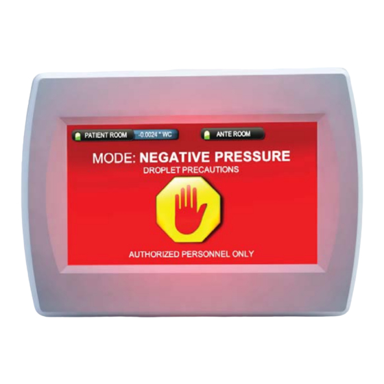
- Page 4 4.1. show only one pressure status icon on upper right corner). The room icons will indicate selected for that space. Primary room pressure status (Green = OK, Amber = Loss of Pressure, Red = Pressure Alarm) Primary room name Secondary Room Pressure Status* Current Room Pressure Current Room P (to Hide / Show...
- Page 5 4.2. to indicate that the room is in use. Background Colors Available: Room Pressure Monitor and Controller - User Guide © 2012 CRITICAL ROOM CONTROL...
- Page 6 4.3. Secondary Room goes outside of the pressure alarm high and low parameters, then the unit will go into pressure alarm and display which room is in pressure alarm. If an audible alarm delay (nuisance delay) is used - then the "Loss of Pressure" screen with an amber PRESSURE NORMAL LOSS OF PRESSURE Pressure icon turns red...
- Page 7 4.4. • Pressurized Mode • No Pressure Mode • Cleaning Mode • Vacant Mode • Clearing MAIN SCREEN Select “MODE” button CLICK “MODE” BUTTON MAIN MENU Select “Change MODE” button CLICK “Change MODE” BUTTON CHANGE ISO MODE SCREEN Shows current mode Select desired mode Select appropriate precautions or choose to “Hide”...
- Page 8 • • • • • • Countdown timer shows how much time is left in clearing mode in minutes and seconds Background color changes to Yellow and ICON changes to clearly indicate clearing mode Room Pressure Monitor and Controller - User Guide ©...
- Page 9 MAIN SCREEN TOUCH anywhere on Main Screen to bring up MODE and MORE INFO button Press the “MORE INFO” button to access the More Info Screen NOTE: If one or more of the points on the secondary screen is in alarm or has been muted, then the "MORE INFO"...
- Page 10 access. Second Room Setup is only available on RPM2 and RPC2 Control Setup is only available on RPC1 and RPC2 • • • • • • • • • Room Pressure Monitor and Controller - User Guide © 2012 CRITICAL ROOM CONTROL...
- Page 11 ALARM TRIGGER: PRESSURE INPUT: Signal from the Pressure Local: Uses alarm high / low below as an alarm range Sensor Network: Pressure Alarm triggered via BACnet Point Netw • Network • AI 0-5v, 0-10v • AI 1-5v, 2-10v • AI 4-20mA ROOM NAME: Text used for the •...
- Page 12 PRIMARY ROOM SETUP SCREEN Select “More Info SET” button SELECT “MORE INFO SET” MORE INFO SETUP SCREEN 1 to 0.0001 Name of Point. If point Setup ‘MORE INFO’ Screen: PATIENT ROOM ROOM text is blank then point will be hidden Point Text/Title: Eng.
- Page 13 I Gain: (Integral Multiplier) This value is the P Gain: (Proportional Multiplier) This value is integral multiplier which effects how closely / the proportional multiplier which effects sharply the control signal (signal output to the how closely / sharply the control signal air control device) will react to an overshooting (signal output to the air control device) will of the pressure set point .
- Page 14 Custom Text: Facilities can enter custom text labels for each mode (up Green Background: to 19 characters). Unused modes can be turned off / hidden by clearing ring the text. Custom Text (Mode) Setup Text (Mode) Setup Blue Background: ISO Text: ISO Text: POSITIVE PRESSURE POSITIVE PRESSURE...
- Page 15 • • • main screen. token passing. Select network Baud Rate: 9600, 19200, 38400, 57600, 76800 or 115,200 MAC Address: 0 – 254 MAC Address: 0 – 254 Note: MAC address must be unique for each device Note: MAC address must b on a specific MS/TP trunk on a specific MS/TP trunk Network Setup...
- Page 16 • • • : This number increases as this unit responds to : This number increases as this unit responds to • : This number increases when this unit sends out a • message (including passing a token). • • •...
- Page 17 ANALOG VALUES General AV 0 Analog Input 1 Read Only (0-100%) AV 1 Analog Input 2 Read Only (0-100%) AV 2 Analog Input 3 Read Only (0-100%) AV 3 Analog Input 4 Read Only (0-100%) Primary Room AV 4 Current P * Float Read rite...
- Page 18 More Info - Secondary AV 36 Point 1 Current Value * Float Read rite AV 37 Point 2 Current Value * Float Read rite AV 38 Point 3 Current Value * Float Read rite AV 39 Point 4 Current Value * Float Read rite...
- Page 19 Indicates monitor run time since being powered Controller Diagnostics Contro Analog Out: Run Time: Time Time Time: 0:00:21:03 Graphical indication of analog inputs Analog Input (in percent): Analo in percent of signal (Note if using AI 0: AI 0 4-20mA pressure transducer “0” will AI 1: AI 2: AI 2:...
- Page 20 12.1 *Must be mounted less than 20' from LCD screen. enclosure. *Pickup plates can be located up to 200' from pressure transducer. 12.2 • Power draw is 18VA max. (0.75amps at 24VAC) • • • • • circuits • • 12.3 Room Pressure Monitor and Controller - User Guide ©...
- Page 21 12.4 (1) CRC-RA Remote Annunciator (Single Room) down a wall. The two components are the monitor and the pressure Room Pressure Monitor and Controller - User Guide © 2014 CRITICAL ROOM CONTROL...
- Page 22 Dual Gang electrical box (Raco 232) Dual Gang mud ring: 5/8" sheetrock (Raco 8768) ½” sheetrock (Raco 8837) CRC-RPM/RPC mounting bracket CRC RPM / RPC LCD CRC RPM / RPC LCD Monitor Monitor CRC-RPM/ RPC set screw Single Gang Masonry box:...
- Page 23 ¼” pneumatic tubing ¼” pneumatic tubing CRC-RST: Room CRC-RST: Room Static Static Transmitter Transmitter (Wall Mount) (Ceiling Mount) CRC-RJ45 CRC-RJ45 CRC-RPM / RPC LCD CRC-RPM / RPC LCD Pneumatic Tubing CRC-RST CRC-RST HI port to LOW port to Controlled space...
- Page 24 12.9 12.10 13.1 (i.e.; temperature and humidity readings), and control parameters (i.e. remote silencing an audible alarm, and changing pressure set point). 13.2 should be less than 100pf per meter. Foil and braided shields are acceptable. The nodes. 13.3 follow. Room Pressure Monitor and Controller - User Guide ©...
- Page 25 RLY1 Pressure Alarm Status 1 RLY1 RLY2 Pressure Alarm Status 2 RLY2 RLY3 Isolation/Non-Isolation Status RLY3/4 RLY4 DIN1 Door Contact 1 DIN2 Door Contact 2 DIN3 Audible Alarm Silence DIN4 +10V AIN4 Mode Change in AIN3 Differential Pressure 2 (RPM2 &RPC2 ) AIN2 Differential Pressure 1 AIN1...
- Page 26 RPM1/RPM2 & RPC1/RPC2 Connection to Primary Room Differential Pressure Transducer (CRC-DPT) CRC-RPM1(2)/RPC1(2) AIN1 CONTROLLER I/O RPM2/RPC2 Connection to Secondary Room Differential Pressure Transducer (CRC-DPT) CRC-RPM2/RPC2 AIN2 CONTROLLER I/O Confirm that Multimeter is set to read Amps DC Confirm that the "Hi" and "Low"...
- Page 27 RPC1/RPC2 Primary Room Pressure control connection to fast acting actuator (CRC-ACT) CRC-RPC1/RPC2 AGND CONTROLLER I/O AOUT3 24 Volt Power Supply 24 VAC ****DO NOT POWER FROM CRC Controller 24 VAC RPC2 Secondary Room Pressure control connection to fast acting actuator (CRC-ACT)
- Page 28 AOUT3 RPC2 Secondary Room Pressure Control Connection to Variable Frequency Drive CRC-RPC2 AGND CONTROLLER I/O AOUT4 RPM1/RPM2 & RPC1/RPC2 Primary Room Connection to Door Contact (CRC-DC) CRC-RPM1(2)/RPC1(2) DIN1 CONTROLLER I/O RPM2 Secondary Room Connection to Door Contact (CRC-DC) CRC-RPM2/RPC2 DIN2...
- Page 29 • Follow the prompts to touch the • controller will then restart itself Critical Room Control CRC - Room Pressure Monitor further steps are needed. Touch To Calibrate Screen ..... complete these following steps to ensure that Room Pressure Monitor and Controller - User Guide...
- Page 30 Room Pressure Monitor and Controller - User Guide © 2014 CRITICAL ROOM CONTROL...
Need help?
Do you have a question about the CRC-RPM and is the answer not in the manual?
Questions and answers