Table of Contents
Advertisement
Quick Links
INSTALLATION INSTRUCTIONS FOR THE DUCT SMOKE DETECTOR
These are Installation Instructions (DWG.# HA-06-184) for the Analog Duct Housing customized as follows:
FAD-325
Duct Housing with the FAD-325-DH Analog Photoelectric Smoke Sensor*
FAD-325-V2F
Duct Housing with the FAD-325-V2F-DH Analog Photoelectric Smoke Sensor*
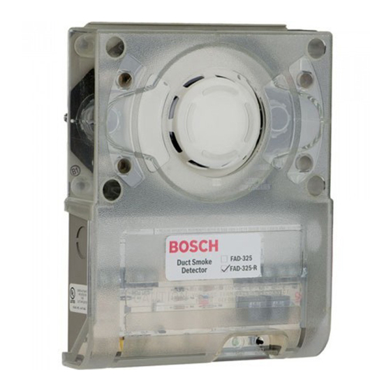
FAD-325-R
Duct Housing with the FAD-325-DH Analog Photoelectric Smoke Sensor & Relays*
FAD-325-V2F-R
Duct Housing with the FAD-325-V2F-DH Analog Photoelectric Smoke Sensor & Relays*
*These products are compatible exclusively with fire alarm control panels that utilize BOSCH's protocol, DCP.
I. LOCATION REQUIREMENTS
Duct Smoke Detector Location Requirements:
detectors should not be mounted in areas of extreme high or low temperatures, in
areas where high humidity exist, or in areas where duct air may contain gases or
excess dust. The duct detector should, when possible, be located a minimum of six
duct widths downstream from a source of turbulence (bends, inlets, or deflection
plates). At these locations, air flow is less turbulent and the air/smoke mixture
should be more homogenous.Refer to NFPA 90A, 72, and 101 for more information.
See Figure 1A and 1B.
Exception: Where it is physically impossible to locate the duct detector accordingly,
the duct detector can be positioned closer than six duct widths, but as far as
possible from inlets, bends, or deflection plates
II. MOUNTING THE DETECTOR
A. DUCT PREPARATION
1. Remove paper backing from mounting template AP 121 (packaged in installation kit) and affix to
duct at desired location.
2. Using template as a guide, drill 4 mounting holes (3/32" diameter) for duct mounting screws (4 #12
x 1/2" sheet metal screws packaged in installation kit). Drill or punch holes for sampling tubes in air
ducts (1-3/8" diameter), using template as a guide. Clean all holes.
B. VERIFY AIR FLOW AND DIRECTION
The Duct Detectors are designed for use in ducts where the air velocities are from 300 to 4000 feet per
minute. Verify this by checking specifications of installation and if necessary, use an Alnor Model
6000P velocity meter (or equivalent) to check the air velocity. See Figure 2 for sampling tube
orientation to air flow direction.
C. SAMPLING TUBE ASSEMBLY (See Figure 2)
The sampling tubes may be ordered to a desired length or ordered in one of 3 standard lengths and cut
per requirements. The intake sampling tube consists of a piece of steel piping with a series of holes
drilled the entire length of the tube and should extend the entire width of the duct. The holes must be
facing into the air flow (see Figure 2). The exhaust tube consists of a piece of steel piping
approximately 7-1/2" long.
INTAKE SAMPLING TUBES STANDARD LENGTHS:
1. Cut the intake sampling tube to the desired length.
2. Firmly insert the stopper (packaged in installation kit) in the end of the INTAKE sampling tube.
D. MOUNT SAMPLING TUBES (See Figure 2)
1. Sampling tube connectors are equipped with set screws, which allow the tubes to be mounted
only in directions shown in Figure 2. Establish proper orientation considering airflow direction.
2. Insert intake and exhaust tubes into connectors, align set screw to set screw hole in tubes and
tighten firmly.
E. MOUNT THE DUCT HOUSING (See Figure 1B & 2)
Move duct housing/sampling tube assembly to desired location. Use 4 mounting screws (4 #12 x 1/2" sheet
metal screws, packaged in installation kit) to secure the housing to the air duct.
F. VERIFY AIR SAMPLING (See Figure 3)
To verify proper sampling of air, use a Dwyer Model 4000 differential pressure gauge (or equivalent).
See Figure 3 for gauge connections. The pressure differential between input sampling tube and
exhaust tube should be greater than 0.01" of water and less than 1.2" of water.
III. ELECTRICAL INSTALLATION
A. GENERAL INFORMATION
Wiring must conform to applicable local codes, ordinances and regulations covering these types of devices. Wire the detectors according to the engineering drawings for the
particular job requirements. These detectors are not intended for open area protection, nor should they be used for open air protection. Refer to NFPA 90A and NFPA 72 for
general and additional information on Duct Smoke Detectors concerning operation and installation. Terminals are suitable for up to #14 gauge wire.
B. DETECTOR WIRING
1. With power source de-energized and the smoke detector not installed, wire all connections per engineering drawings.
Refer to the applicable figures below depending on your duct housing model number.
2. With all wiring in place, install the detector head.
3. Energize the duct detector.
Models FAD-325/FAD-325-V2F/ FAD-325-R and FAD-325-V2F-R
These duct sensors are analog addressable and can be calibrated by a U.L. Listed analog control panel. See the FACP Installation
Instructions for specific directions.
Note: All duct detector models can be tested with actual smoke. Remove the duct detector cover. Test the detector head by lighting a piece of cotton
clothesline. and placing it approximately 3 inches from the detector head. Blow across the lit end of the clothesline toward the detector. The LEDs on the
detector should illuminate within one minute. After performing this test sequence, reinstall the duct detector cover.
BOSCH Security Systems, Inc. * FAD-325 Installation Instructions (HA-06-184. P/N 1700-11140 Page 1 of 2)
To prevent false alarms the
.
FAA-325-2.5
For duct widths of 1.0' to 2.5'
FAA-325-5
For duct widths of 2.5' to 5.0'
FAA-325-10
For duct widths of 5.0' to 10.0'
BOSCH SECURITY SYSTEMS, INC.
130 Perinton Parkway
Fairport, NY 14450 USA
TEMPLATE
Bend or
Other
Obstruction
6 Duct
Widths
Minimum
FIGURE 1A
SET
SCREW
INSERT STOPPER AT THIS END OF
INTAKE TUBE
AIR FLOW
INTAKE
TUBE
SUPPORTED
EXHAUST
THE DUCT IS
TUBE
THAN 3 FEET.
TOP OF DUCT HOUSING
FIGURE 2 SAMPLING TUBE ORIENTATION
EXHAUST TUBE
HOLE &
CONNECTOR
LOW PRESSURE
SIDE
FIG. 3 AIR SAMPLING
VERIFICATION
Specifications subject to change without notice. * February 2017
STOPPER
AIR FLOW
FOR THIS
ILLUSTRATION
INTAKE
SAMPLING
TUBE
EXHAUST
TUBE
CONNECTORS
DUCT MOUNTING
SCREWS
TOP OF DUCT HOUSING
F
IGURE 1B: DUCT HOUSING MOUNTING
INTAKE
AIR FLOW
SAMPLING
TUBE TO BE
INTAKE
TUBE
WHERE THE
WIDTH OF
EXHAUST
TUBE
GREATER
TOP OF DUCT HOUSING
INTAKE TUBE
HOLE &
CONNECTOR
HIGH PRESSURE
SIDE
DWYER #4000 DIFFERENTIAL
PRESSURE GAUGE (OR
EQUIVALENT) WITH TUBING
AND SIZE 0 RUBBER STOPPERS
(HA PART# 0700-01118).
Advertisement
Table of Contents

Related Manuals for Bosch FAD-325-V2F


Summary of Contents for Bosch FAD-325-V2F
- Page 1 Duct Housing with the FAD-325-DH Analog Photoelectric Smoke Sensor & Relays* FAD-325-V2F-R Duct Housing with the FAD-325-V2F-DH Analog Photoelectric Smoke Sensor & Relays* *These products are compatible exclusively with fire alarm control panels that utilize BOSCH's protocol, DCP. I. LOCATION REQUIREMENTS STOPPER...
- Page 2 * A common Remote reset switch will reset all detectors. Specifications subject to change without notice. * February 2017 BOSCH Security Systems, Inc. * FAD-325 Installation Instructions (HA-06-184. P/N 1700-11140 Page 2 of 2)
Need help?
Do you have a question about the FAD-325-V2F and is the answer not in the manual?
Questions and answers